EP2803476A1 - Pressmaschine - Google Patents
Pressmaschine Download PDFInfo
- Publication number
- EP2803476A1 EP2803476A1 EP13735918.8A EP13735918A EP2803476A1 EP 2803476 A1 EP2803476 A1 EP 2803476A1 EP 13735918 A EP13735918 A EP 13735918A EP 2803476 A1 EP2803476 A1 EP 2803476A1
- Authority
- EP
- European Patent Office
- Prior art keywords
- threaded member
- ram
- bearing
- bearing holder
- motor
- Prior art date
- Legal status (The legal status is an assumption and is not a legal conclusion. Google has not performed a legal analysis and makes no representation as to the accuracy of the status listed.)
- Granted
Links
Images

Classifications
-
- B—PERFORMING OPERATIONS; TRANSPORTING
- B30—PRESSES
- B30B—PRESSES IN GENERAL
- B30B1/00—Presses, using a press ram, characterised by the features of the drive therefor, pressure being transmitted directly, or through simple thrust or tension members only, to the press ram or platen
- B30B1/18—Presses, using a press ram, characterised by the features of the drive therefor, pressure being transmitted directly, or through simple thrust or tension members only, to the press ram or platen by screw means
- B30B1/181—Presses, using a press ram, characterised by the features of the drive therefor, pressure being transmitted directly, or through simple thrust or tension members only, to the press ram or platen by screw means the screw being directly driven by an electric motor
-
- B—PERFORMING OPERATIONS; TRANSPORTING
- B30—PRESSES
- B30B—PRESSES IN GENERAL
- B30B1/00—Presses, using a press ram, characterised by the features of the drive therefor, pressure being transmitted directly, or through simple thrust or tension members only, to the press ram or platen
- B30B1/18—Presses, using a press ram, characterised by the features of the drive therefor, pressure being transmitted directly, or through simple thrust or tension members only, to the press ram or platen by screw means
-
- B—PERFORMING OPERATIONS; TRANSPORTING
- B30—PRESSES
- B30B—PRESSES IN GENERAL
- B30B15/00—Details of, or accessories for, presses; Auxiliary measures in connection with pressing
- B30B15/06—Platens or press rams
- B30B15/068—Drive connections, e.g. pivotal
Definitions
- the present invention relates to a press machine including a nut member rotatably arranged on a frame, a first motor arranged on the frame to rotate the nut member, a threaded member screwed into the nut member so that the threaded member is rotatable and longitudinally movable, a second motor arranged on the nut member to rotate the threaded member, an engaging part engaged with a front end part of the threaded member so that the engaging part rotates relative to the threaded member, and a ram movable with the engaging part in a direction in which the threaded member moves.
- the present invention relates to a press machine capable of smoothly moving the threaded member at high speed.
- Patent Literature 1 proposes a press machine having a motor for vertically moving a ram at high speed and a high-power motor that functions when pressing the ram.
- the press machine described in the Patent Literature 1 has a configuration as illustrated in Fig. 1 .
- the press machine 1 has a frame 3.
- An upper part of the frame 3 has a nut member 5 that is rotatable.
- the nut member 5 has a pulley 7 around which a belt 13 is stretched.
- the belt 13 is also stretched around a drive pulley 11 of a first motor 9 installed on the frame 3. Accordingly, forwardly or reversely turning the first motor 9 results in forwardly or reversely turning the nut member 5 in synchronization.
- the frame 3 has a guide member 15 extending in a vertical direction.
- the guide member 15 vertically movably supports and guides a ram 17.
- the nut member 5 has a threaded member 19 that is inserted through the nut member 5 so that the threaded member 19 is rotatable and vertically movable.
- an upper end part of the threaded member 19 integrally has a pulley 21.
- a belt 27 is stretched.
- the belt 27 is also stretched around a drive pulley 25 of a second motor 23.
- the second motor 23 vertically moves together with the threaded member 19.
- the second motor 23 is vertically movably supported and guided with a vertical guide 31 of a support bracket 29 that is arranged at an outer upper part of the frame 3.
- the second motor 23 has a motor bracket 33 to which a base end part of a connection bar 35 is solidly connected. A front end part of the connection bar 35 is connected to the threaded member 19 so that the threaded member 19 rotates relative to the connection bar 35.
- a front end part (lower end part) of the threaded member 19 is engaged with an engaging part 37 formed at an upper part of the ram 17 so that the threaded part 19 rotates relative to the engaging part 37. More precisely, the lower end part of the threaded member 19 has a flange part 19F and the engaging part 37 has an engaging recess 39 that contains the flange part 19F so that the 5 flange part 19F may rotate.
- the engaging recess 39 incorporates, as illustrated in Fig. 2 , a bearing 41, which restricts vertical movements of the flange part 19F, and an oil seal 43.
- the ram 17 In a normal state with the above-mentioned configuration, the ram 17 is in a state being suspended from the threaded member 19 to form a fine clearance C between a lower face of the flange part 19F of the threaded member 19 and a bottom face (upper face) of the engaging recess 39. As a result, the threaded member 19 can smoothly rotate relative to the ram 17 as illustrated in Fig. 2(A) .
- the second motor 23 may be rotated at high speed to lower the threaded member 19. This results in lowering the ram 17 also at high speed. At this time, the first motor 9 may properly be rotated in a forward or reverse direction to lower the ram 17 at higher or slower speed.
- the ram 17 can vertically be moved at high speed.
- the rotation of the first motor 9 lowers the ram 17 at low speed to apply large pressure to press the work W.
- the threaded member 19 starts to quickly descend relative to the ram 17 that is ascended and stopped.
- a descending speed of the ram 17 that starts to descend by its own weight may become slower than a descending speed of the threaded member 19 and the lower face of the flange part 19F of the threaded member 19 may come into contact with the bottom face of the engaging recess 39 of the ram 17.
- the present invention provides a press machine of the type that vertically moves a ram by turning a threaded member.
- the press machine is characterized in that the ram has a bearing holder that holds a bearing whose outer ring is solidly engaged with the bearing holder and whose inner ring is solidly fitted to a lower end part of the threaded member and in that a fine clearance is formed between a lower face of the threaded member and a bottom face of the bearing holder so that the threaded member and bearing holder are allowed to rotate relative to each other.
- the fine clearance is set so that, when load is applied to the ram to cause a relative slight movement in a vertical direction between the inner and outer rings of the bearing, the lower face of the threaded member and the bottom face of the bearing holder come into contact with each other.
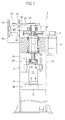
- the press machine 45 has a frame 3 to which a cylindrical support block 47 is fixed.
- the support block 47 internally supports through a plurality of bearings 49 a nut member 5 that is rotatable.
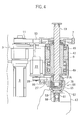
- An upper part of the nut member 5 integrally has a pulley 7 (refer to Fig. 4 ) around which a belt 13 is stretched.
- the belt 13 is also stretched around a drive pulley 11 provided for a first motor 9 that is installed on a part of the frame 3. Accordingly, forwardly or reversely rotating the first motor 9 forwardly or reversely rotates the nut member 5.
- a threaded member 19 is screwed to move in a longitudinal direction, i.e., a vertical direction.
- a lower part of the threaded member 19 is connected to a ram 17.
- An upper part of the ram 17 has an engaging part 51 corresponding to the engaging part 37 so that the engaging part 51 may sway in a left-right direction (the left-right direction in Fig. 4 ).
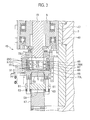
- an upper face of the ram 17 has an arc-like concave face 53 formed in a front-rear direction (a direction perpendicular to the surface of Fig. 4 or a left-right direction in Fig. 3 ).
- the concave face 53 receives an arc-like convex face formed on a lower face of a swaying engaging member 57 provided for a lower face of a swayable pressurizing member 55.
- a fixing tool 61 such as a fixing bolt vertically passes through each of front and rear ends of a through rod 59 that rotatably passes through the ram 17 in the front-rear direction.
- a front end (upper end) of the fixing tool 61 is screwed into and connected to the pressurizing member 55.
- an elastic member 63 such as a disk spring to downwardly push the fixing member 61.
- the concave face 53 and the convex face of the swaying engaging member 57 may be formed into semispherical concave and convex faces to allow the ram 17 and pressurizing member 55 sway relative to each other in the front-rear and left-right directions.
- an upper face of the pressurizing member 55 is integrally provided with a bearing holder 69 incorporating bearings 65 and 67 that are laid one on another.
- the bearings 65 and 67 rotatably support the lower end part of the threaded member 19. More precisely, the bearings 65 and 67 are angular bearings and the upper and lower bearings 65 and 67 are arranged so that contact angles among their inner rings 65I and 67I, balls 71, and outer rings 650 and 670 are opposite to one another. Namely, the contact angle on the upper bearing 65 is a downwardly widening contact angle and that on the lower bearing 67 is an upwardly widening contact angle.
- the outer rings 650 and 670 of the bearings 65 and 67 are solidly engaged (fitted) with the bearing holder 69. Namely, the outer rings 650 and 670 of the bearings 65 and 67 are fitted to the bearing holder 69 so that the outer rings 650 and 670 are unable to vertically move relative to the bearing holder 69.
- the lower end part of the threaded member 19 is inserted into the inner rings 65I and 67I of the bearings 65 and 67 so that the threaded member 19 is unable to vertically move relative to the inner rings 65I and 67I.
- a lower part of the threaded member 19 integrally has flange parts 73U and 73L to restrict the relative vertical movement of the inner rings 65I and 67I.
- the bearing holder 69 and threaded member 19 are rotatable relative to each other.
- the threaded member 19 and bearing holder 69 are tightly connected to each other.
- a fine clearance C is formed between the lower face of the threaded member 19, i.e., a lower face 75 of the flange part 73L and a bottom face 77 of the bearing holder 69.
- the fine clearance C is set so that, when the pressing process creates load to upwardly push the ram 17 and elastically deform the balls 71, the lower face 75 and bottom face 77 come into contact with each other.
- the fine clearance C is in the order of micrometers (for example, 20 micrometers).
- the bearing holder 69 is provided with the bottom face 77. If the bearing holder 69 has a through cylindrical shape, an upper face of the pressuring member 55 may serve as the bottom face 77. In this case, the upper face of the pressurizing member 55 defines the bottom face of the bearing holder 69.
- An upper side of the upper flange part 73U is solidly provided with a pulley 21A corresponding to the pulley 21, to rotate the threaded member 19.
- An upper face of the pressurizing member 55 is solidly provided with a motor support bracket 79.
- the bearing holder 69 is fitted into a fitting hole 79H formed in the motor support bracket 79.
- the motor support bracket 79 is solidly provided with a motor bracket 81 that supports a second motor 23.
- a belt 27 is stretched around a drive pulley 25 of the second motor 23 and the pulley 21A.
- the press machine of the embodiment provides functions and effects similar to those provided by the press machine of the related art.
- the ram 17 starts descending not by its own weight but by the downward push by the threaded member 19. Accordingly, there is no delay from the start of descent of the threaded member 19 to the start of descent of the ram 17 and the ram 17 smoothly follows the vertical movement of the threaded member 19.
- pressing reaction acts on the ram 17, and in the bearings 65 and 67, force acts to lift the outer rings 650 and 670 relative to the inner rings 65I and 67I.
- the reaction (load) acting on the ram 17 during the pressing process elastically deforms the balls 71 of the bearings 65 and 67. Due to the elastic deformation, the lower face 75 of the threaded member 19 and the bottom face 77 of the bearing holder 69 come into contact with each other to create friction that makes the threaded member 19 unable to rotate.
- the lower end part of the threaded member 19 downwardly protruding from the nut member 5 is provided with the pulley 21A and the motor support bracket 79 arranged to turn relative to the threaded member 19 is provided with the second motor 23 for rotating the pulley 21A.
- This configuration suppresses an overall height of the press machine, simplifies the structure thereof, and reduces the size thereof.
- the bearings 65 and 67 are not limited to the angular bearings. They may be thrust bearings. They may not be limited to the ball bearings but may be roller bearings.
- the fine clearance is defined between the bottom face of the bearing holder containing the bearings and the lower face of the threaded member whose lower end part is solidly fitted to the bearings of the bearing holder.
- the fine clearance is set so that, when load is applied to the ram to slightly vertically move the inner and outer rings of the bearings relative to each other, the bottom face and lower face come into contact with each other. Until load is applied to the ram, the bottom face and lower face never come into contact with each other, to allow the threaded member to smoothly rotate.
Landscapes
- Engineering & Computer Science (AREA)
- Mechanical Engineering (AREA)
- Press Drives And Press Lines (AREA)
Applications Claiming Priority (2)
| Application Number | Priority Date | Filing Date | Title |
|---|---|---|---|
| JP2012002062A JP5913989B2 (ja) | 2012-01-10 | 2012-01-10 | プレス機械 |
| PCT/JP2013/050102 WO2013105547A1 (ja) | 2012-01-10 | 2013-01-08 | プレス機械 |
Publications (3)
| Publication Number | Publication Date |
|---|---|
| EP2803476A1 true EP2803476A1 (de) | 2014-11-19 |
| EP2803476A4 EP2803476A4 (de) | 2015-12-23 |
| EP2803476B1 EP2803476B1 (de) | 2019-04-17 |
Family
ID=48781494
Family Applications (1)
| Application Number | Title | Priority Date | Filing Date |
|---|---|---|---|
| EP13735918.8A Active EP2803476B1 (de) | 2012-01-10 | 2013-01-08 | Pressmaschine |
Country Status (5)
| Country | Link |
|---|---|
| US (1) | US10513087B2 (de) |
| EP (1) | EP2803476B1 (de) |
| JP (1) | JP5913989B2 (de) |
| CN (1) | CN104039543B (de) |
| WO (1) | WO2013105547A1 (de) |
Families Citing this family (6)
| Publication number | Priority date | Publication date | Assignee | Title |
|---|---|---|---|---|
| EP2853322A1 (de) * | 2013-09-30 | 2015-04-01 | Seco Tools AB | Presse zur Herstellung eines Werkzeug-Grünkörpers mit einer spiralförmigen Nut, Verfahren zur Herstellung eines Werkzeug-Grünkörpers mit einem spiralförmigen Nut, und Werkzeug-Grünkörper mit einer spiralförmigen Nut |
| KR101769076B1 (ko) * | 2013-10-02 | 2017-08-17 | 무라다기카이가부시끼가이샤 | 프레스 기계 및 프레스 방법 |
| CA3016929C (en) * | 2016-03-18 | 2022-11-08 | Anaergia B.V. | Press ram fastening system |
| JP6655465B2 (ja) * | 2016-05-09 | 2020-02-26 | 株式会社アマダホールディングス | プレス機械 |
| JP6662467B2 (ja) * | 2016-10-27 | 2020-03-11 | 村田機械株式会社 | プレスブレーキ |
| CN112046062A (zh) * | 2020-10-10 | 2020-12-08 | 沈天星 | 一种生物质固体燃料生产用成型压块装置 |
Family Cites Families (12)
| Publication number | Priority date | Publication date | Assignee | Title |
|---|---|---|---|---|
| DE1427417A1 (de) * | 1961-04-07 | 1968-11-21 | Berrenberg Fa Franz | Friktionsspindelpresse |
| US4196947A (en) * | 1978-02-22 | 1980-04-08 | Clark Equipment Company | Adjustable four point contact bearing |
| JPH0315038U (de) * | 1989-06-29 | 1991-02-15 | ||
| JP2592473Y2 (ja) * | 1992-10-09 | 1999-03-24 | 富士重工業株式会社 | ピアス加工用プレス型 |
| JP3015038U (ja) * | 1995-02-22 | 1995-08-29 | 株式会社名機製作所 | 電動プレスの早送り機構 |
| JP3953414B2 (ja) * | 2002-12-11 | 2007-08-08 | 株式会社東洋工機 | 往復駆動機構およびその機構を用いたプレス機械 |
| JP4373399B2 (ja) * | 2003-12-03 | 2009-11-25 | 株式会社放電精密加工研究所 | プレス装置 |
| JP3664406B1 (ja) * | 2004-09-16 | 2005-06-29 | サイエンティフィックテクノロジーズ有限会社 | 負荷感応推力増幅機構を持つ動力伝達方法及び装置 |
| JP2008018444A (ja) * | 2006-07-12 | 2008-01-31 | Amada Co Ltd | 加圧装置およびワークの角部成形装置 |
| JP4941825B2 (ja) * | 2007-02-05 | 2012-05-30 | 新東工業株式会社 | 加圧成型装置 |
| JP5603608B2 (ja) | 2010-01-29 | 2014-10-08 | 株式会社アマダ | マーキング加工方法、マーキング加工工具、パンチプレス |
| JP5699618B2 (ja) * | 2011-01-13 | 2015-04-15 | 新東工業株式会社 | 電動シリンダシステム |
-
2012
- 2012-01-10 JP JP2012002062A patent/JP5913989B2/ja active Active
-
2013
- 2013-01-08 US US14/371,012 patent/US10513087B2/en active Active
- 2013-01-08 EP EP13735918.8A patent/EP2803476B1/de active Active
- 2013-01-08 CN CN201380005128.0A patent/CN104039543B/zh active Active
- 2013-01-08 WO PCT/JP2013/050102 patent/WO2013105547A1/ja not_active Ceased
Also Published As
| Publication number | Publication date |
|---|---|
| JP5913989B2 (ja) | 2016-05-11 |
| JP2013141675A (ja) | 2013-07-22 |
| US20140360388A1 (en) | 2014-12-11 |
| EP2803476A4 (de) | 2015-12-23 |
| CN104039543B (zh) | 2015-11-25 |
| EP2803476B1 (de) | 2019-04-17 |
| CN104039543A (zh) | 2014-09-10 |
| US10513087B2 (en) | 2019-12-24 |
| WO2013105547A1 (ja) | 2013-07-18 |
Similar Documents
| Publication | Publication Date | Title |
|---|---|---|
| EP2803476B1 (de) | Pressmaschine | |
| JP6662467B2 (ja) | プレスブレーキ | |
| JP6419771B2 (ja) | プレス機 | |
| CN110695224B (zh) | 一种用于滑靴收口的机床 | |
| JP2013000772A (ja) | リベッティングマシン及びリベッティング方法 | |
| JP5565973B2 (ja) | スライド駆動装置 | |
| KR20120100932A (ko) | 공작기계의 밸런싱 장치 | |
| CN101102886A (zh) | 模具缓冲装置 | |
| CN208226815U (zh) | 电机转子装配机 | |
| KR101823411B1 (ko) | 제동장치 | |
| JPH091258A (ja) | タレットパンチプレス機による軟質材料及び軟質積層材料の孔あけ方法 | |
| KR20180087752A (ko) | 금형 승강장치를 구비한 전단금형장치 | |
| JP4815019B1 (ja) | ハイブリッド式プレス装置 | |
| JP5723613B2 (ja) | プレス機械 | |
| JP2001150191A (ja) | 加圧装置 | |
| JP6649175B2 (ja) | プレス機械 | |
| JP2008272898A (ja) | 工作機械における工具のアンクランプ方法 | |
| JP2005246464A (ja) | 機械プレスの制御方法及びその制御装置 | |
| CN220739304U (zh) | 一种汽车座椅头枕加工用数控车床 | |
| CN206464632U (zh) | 机床压力脚机构及锣机 | |
| JP2009142894A (ja) | ダイクッション装置及びプレス機械 | |
| CN117620017A (zh) | 一种汽车电动座椅调角器内齿板压铆机 | |
| CN121624814A (zh) | 一种具有压力缓冲与防过载功能的压装机 | |
| CN121572034A (zh) | 压紧装置 | |
| JP2017202490A (ja) | プレス機械 |
Legal Events
| Date | Code | Title | Description |
|---|---|---|---|
| PUAI | Public reference made under article 153(3) epc to a published international application that has entered the european phase |
Free format text: ORIGINAL CODE: 0009012 |
|
| 17P | Request for examination filed |
Effective date: 20140729 |
|
| AK | Designated contracting states |
Kind code of ref document: A1 Designated state(s): AL AT BE BG CH CY CZ DE DK EE ES FI FR GB GR HR HU IE IS IT LI LT LU LV MC MK MT NL NO PL PT RO RS SE SI SK SM TR |
|
| DAX | Request for extension of the european patent (deleted) | ||
| RA4 | Supplementary search report drawn up and despatched (corrected) |
Effective date: 20151123 |
|
| RIC1 | Information provided on ipc code assigned before grant |
Ipc: B30B 1/18 20060101AFI20151117BHEP |
|
| REG | Reference to a national code |
Ref country code: DE Ref legal event code: R079 Ref document number: 602013054006 Country of ref document: DE Free format text: PREVIOUS MAIN CLASS: B30B0001180000 Ipc: B30B0015060000 |
|
| RIC1 | Information provided on ipc code assigned before grant |
Ipc: B30B 1/18 20060101ALI20180926BHEP Ipc: B30B 15/06 20060101AFI20180926BHEP |
|
| GRAP | Despatch of communication of intention to grant a patent |
Free format text: ORIGINAL CODE: EPIDOSNIGR1 |
|
| STAA | Information on the status of an ep patent application or granted ep patent |
Free format text: STATUS: GRANT OF PATENT IS INTENDED |
|
| INTG | Intention to grant announced |
Effective date: 20181113 |
|
| GRAS | Grant fee paid |
Free format text: ORIGINAL CODE: EPIDOSNIGR3 |
|
| GRAA | (expected) grant |
Free format text: ORIGINAL CODE: 0009210 |
|
| STAA | Information on the status of an ep patent application or granted ep patent |
Free format text: STATUS: THE PATENT HAS BEEN GRANTED |
|
| AK | Designated contracting states |
Kind code of ref document: B1 Designated state(s): AL AT BE BG CH CY CZ DE DK EE ES FI FR GB GR HR HU IE IS IT LI LT LU LV MC MK MT NL NO PL PT RO RS SE SI SK SM TR |
|
| REG | Reference to a national code |
Ref country code: GB Ref legal event code: FG4D |
|
| REG | Reference to a national code |
Ref country code: CH Ref legal event code: EP |
|
| REG | Reference to a national code |
Ref country code: DE Ref legal event code: R096 Ref document number: 602013054006 Country of ref document: DE |
|
| REG | Reference to a national code |
Ref country code: AT Ref legal event code: REF Ref document number: 1121074 Country of ref document: AT Kind code of ref document: T Effective date: 20190515 Ref country code: IE Ref legal event code: FG4D |
|
| REG | Reference to a national code |
Ref country code: DE Ref legal event code: R082 Ref document number: 602013054006 Country of ref document: DE Representative=s name: GRUENECKER PATENT- UND RECHTSANWAELTE PARTG MB, DE |
|
| REG | Reference to a national code |
Ref country code: NL Ref legal event code: MP Effective date: 20190417 |
|
| RAP2 | Party data changed (patent owner data changed or rights of a patent transferred) |
Owner name: AMADA HOLDINGS CO., LTD. |
|
| REG | Reference to a national code |
Ref country code: LT Ref legal event code: MG4D |
|
| REG | Reference to a national code |
Ref country code: DE Ref legal event code: R082 Ref document number: 602013054006 Country of ref document: DE Representative=s name: GRUENECKER PATENT- UND RECHTSANWAELTE PARTG MB, DE Ref country code: DE Ref legal event code: R081 Ref document number: 602013054006 Country of ref document: DE Owner name: AMADA HOLDINGS CO., LTD, ISEHARA-SHI, JP Free format text: FORMER OWNER: AMADA COMPANY, LIMITED, ISEHARA-SHI, KANAGAWA, JP |
|
| PG25 | Lapsed in a contracting state [announced via postgrant information from national office to epo] |
Ref country code: NL Free format text: LAPSE BECAUSE OF FAILURE TO SUBMIT A TRANSLATION OF THE DESCRIPTION OR TO PAY THE FEE WITHIN THE PRESCRIBED TIME-LIMIT Effective date: 20190417 |
|
| PG25 | Lapsed in a contracting state [announced via postgrant information from national office to epo] |
Ref country code: SE Free format text: LAPSE BECAUSE OF FAILURE TO SUBMIT A TRANSLATION OF THE DESCRIPTION OR TO PAY THE FEE WITHIN THE PRESCRIBED TIME-LIMIT Effective date: 20190417 Ref country code: HR Free format text: LAPSE BECAUSE OF FAILURE TO SUBMIT A TRANSLATION OF THE DESCRIPTION OR TO PAY THE FEE WITHIN THE PRESCRIBED TIME-LIMIT Effective date: 20190417 Ref country code: LT Free format text: LAPSE BECAUSE OF FAILURE TO SUBMIT A TRANSLATION OF THE DESCRIPTION OR TO PAY THE FEE WITHIN THE PRESCRIBED TIME-LIMIT Effective date: 20190417 Ref country code: ES Free format text: LAPSE BECAUSE OF FAILURE TO SUBMIT A TRANSLATION OF THE DESCRIPTION OR TO PAY THE FEE WITHIN THE PRESCRIBED TIME-LIMIT Effective date: 20190417 Ref country code: AL Free format text: LAPSE BECAUSE OF FAILURE TO SUBMIT A TRANSLATION OF THE DESCRIPTION OR TO PAY THE FEE WITHIN THE PRESCRIBED TIME-LIMIT Effective date: 20190417 Ref country code: FI Free format text: LAPSE BECAUSE OF FAILURE TO SUBMIT A TRANSLATION OF THE DESCRIPTION OR TO PAY THE FEE WITHIN THE PRESCRIBED TIME-LIMIT Effective date: 20190417 Ref country code: PT Free format text: LAPSE BECAUSE OF FAILURE TO SUBMIT A TRANSLATION OF THE DESCRIPTION OR TO PAY THE FEE WITHIN THE PRESCRIBED TIME-LIMIT Effective date: 20190817 Ref country code: NO Free format text: LAPSE BECAUSE OF FAILURE TO SUBMIT A TRANSLATION OF THE DESCRIPTION OR TO PAY THE FEE WITHIN THE PRESCRIBED TIME-LIMIT Effective date: 20190717 |
|
| PG25 | Lapsed in a contracting state [announced via postgrant information from national office to epo] |
Ref country code: LV Free format text: LAPSE BECAUSE OF FAILURE TO SUBMIT A TRANSLATION OF THE DESCRIPTION OR TO PAY THE FEE WITHIN THE PRESCRIBED TIME-LIMIT Effective date: 20190417 Ref country code: PL Free format text: LAPSE BECAUSE OF FAILURE TO SUBMIT A TRANSLATION OF THE DESCRIPTION OR TO PAY THE FEE WITHIN THE PRESCRIBED TIME-LIMIT Effective date: 20190417 Ref country code: GR Free format text: LAPSE BECAUSE OF FAILURE TO SUBMIT A TRANSLATION OF THE DESCRIPTION OR TO PAY THE FEE WITHIN THE PRESCRIBED TIME-LIMIT Effective date: 20190718 Ref country code: RS Free format text: LAPSE BECAUSE OF FAILURE TO SUBMIT A TRANSLATION OF THE DESCRIPTION OR TO PAY THE FEE WITHIN THE PRESCRIBED TIME-LIMIT Effective date: 20190417 Ref country code: BG Free format text: LAPSE BECAUSE OF FAILURE TO SUBMIT A TRANSLATION OF THE DESCRIPTION OR TO PAY THE FEE WITHIN THE PRESCRIBED TIME-LIMIT Effective date: 20190717 |
|
| REG | Reference to a national code |
Ref country code: AT Ref legal event code: MK05 Ref document number: 1121074 Country of ref document: AT Kind code of ref document: T Effective date: 20190417 |
|
| PG25 | Lapsed in a contracting state [announced via postgrant information from national office to epo] |
Ref country code: IS Free format text: LAPSE BECAUSE OF FAILURE TO SUBMIT A TRANSLATION OF THE DESCRIPTION OR TO PAY THE FEE WITHIN THE PRESCRIBED TIME-LIMIT Effective date: 20190817 |
|
| REG | Reference to a national code |
Ref country code: DE Ref legal event code: R097 Ref document number: 602013054006 Country of ref document: DE |
|
| PG25 | Lapsed in a contracting state [announced via postgrant information from national office to epo] |
Ref country code: CZ Free format text: LAPSE BECAUSE OF FAILURE TO SUBMIT A TRANSLATION OF THE DESCRIPTION OR TO PAY THE FEE WITHIN THE PRESCRIBED TIME-LIMIT Effective date: 20190417 Ref country code: RO Free format text: LAPSE BECAUSE OF FAILURE TO SUBMIT A TRANSLATION OF THE DESCRIPTION OR TO PAY THE FEE WITHIN THE PRESCRIBED TIME-LIMIT Effective date: 20190417 Ref country code: DK Free format text: LAPSE BECAUSE OF FAILURE TO SUBMIT A TRANSLATION OF THE DESCRIPTION OR TO PAY THE FEE WITHIN THE PRESCRIBED TIME-LIMIT Effective date: 20190417 Ref country code: EE Free format text: LAPSE BECAUSE OF FAILURE TO SUBMIT A TRANSLATION OF THE DESCRIPTION OR TO PAY THE FEE WITHIN THE PRESCRIBED TIME-LIMIT Effective date: 20190417 Ref country code: AT Free format text: LAPSE BECAUSE OF FAILURE TO SUBMIT A TRANSLATION OF THE DESCRIPTION OR TO PAY THE FEE WITHIN THE PRESCRIBED TIME-LIMIT Effective date: 20190417 Ref country code: SK Free format text: LAPSE BECAUSE OF FAILURE TO SUBMIT A TRANSLATION OF THE DESCRIPTION OR TO PAY THE FEE WITHIN THE PRESCRIBED TIME-LIMIT Effective date: 20190417 |
|
| PLBE | No opposition filed within time limit |
Free format text: ORIGINAL CODE: 0009261 |
|
| STAA | Information on the status of an ep patent application or granted ep patent |
Free format text: STATUS: NO OPPOSITION FILED WITHIN TIME LIMIT |
|
| PG25 | Lapsed in a contracting state [announced via postgrant information from national office to epo] |
Ref country code: SM Free format text: LAPSE BECAUSE OF FAILURE TO SUBMIT A TRANSLATION OF THE DESCRIPTION OR TO PAY THE FEE WITHIN THE PRESCRIBED TIME-LIMIT Effective date: 20190417 |
|
| 26N | No opposition filed |
Effective date: 20200120 |
|
| PG25 | Lapsed in a contracting state [announced via postgrant information from national office to epo] |
Ref country code: TR Free format text: LAPSE BECAUSE OF FAILURE TO SUBMIT A TRANSLATION OF THE DESCRIPTION OR TO PAY THE FEE WITHIN THE PRESCRIBED TIME-LIMIT Effective date: 20190417 |
|
| PG25 | Lapsed in a contracting state [announced via postgrant information from national office to epo] |
Ref country code: SI Free format text: LAPSE BECAUSE OF FAILURE TO SUBMIT A TRANSLATION OF THE DESCRIPTION OR TO PAY THE FEE WITHIN THE PRESCRIBED TIME-LIMIT Effective date: 20190417 |
|
| PG25 | Lapsed in a contracting state [announced via postgrant information from national office to epo] |
Ref country code: MC Free format text: LAPSE BECAUSE OF FAILURE TO SUBMIT A TRANSLATION OF THE DESCRIPTION OR TO PAY THE FEE WITHIN THE PRESCRIBED TIME-LIMIT Effective date: 20190417 |
|
| REG | Reference to a national code |
Ref country code: CH Ref legal event code: PL |
|
| REG | Reference to a national code |
Ref country code: BE Ref legal event code: MM Effective date: 20200131 |
|
| PG25 | Lapsed in a contracting state [announced via postgrant information from national office to epo] |
Ref country code: LU Free format text: LAPSE BECAUSE OF NON-PAYMENT OF DUE FEES Effective date: 20200108 |
|
| PG25 | Lapsed in a contracting state [announced via postgrant information from national office to epo] |
Ref country code: LI Free format text: LAPSE BECAUSE OF NON-PAYMENT OF DUE FEES Effective date: 20200131 Ref country code: BE Free format text: LAPSE BECAUSE OF NON-PAYMENT OF DUE FEES Effective date: 20200131 Ref country code: CH Free format text: LAPSE BECAUSE OF NON-PAYMENT OF DUE FEES Effective date: 20200131 |
|
| PG25 | Lapsed in a contracting state [announced via postgrant information from national office to epo] |
Ref country code: IE Free format text: LAPSE BECAUSE OF NON-PAYMENT OF DUE FEES Effective date: 20200108 |
|
| PG25 | Lapsed in a contracting state [announced via postgrant information from national office to epo] |
Ref country code: MT Free format text: LAPSE BECAUSE OF FAILURE TO SUBMIT A TRANSLATION OF THE DESCRIPTION OR TO PAY THE FEE WITHIN THE PRESCRIBED TIME-LIMIT Effective date: 20190417 Ref country code: CY Free format text: LAPSE BECAUSE OF FAILURE TO SUBMIT A TRANSLATION OF THE DESCRIPTION OR TO PAY THE FEE WITHIN THE PRESCRIBED TIME-LIMIT Effective date: 20190417 |
|
| PG25 | Lapsed in a contracting state [announced via postgrant information from national office to epo] |
Ref country code: MK Free format text: LAPSE BECAUSE OF FAILURE TO SUBMIT A TRANSLATION OF THE DESCRIPTION OR TO PAY THE FEE WITHIN THE PRESCRIBED TIME-LIMIT Effective date: 20190417 |
|
| P01 | Opt-out of the competence of the unified patent court (upc) registered |
Effective date: 20230428 |
|
| PGFP | Annual fee paid to national office [announced via postgrant information from national office to epo] |
Ref country code: IT Payment date: 20250129 Year of fee payment: 13 Ref country code: GB Payment date: 20250128 Year of fee payment: 13 |
|
| PGFP | Annual fee paid to national office [announced via postgrant information from national office to epo] |
Ref country code: DE Payment date: 20260121 Year of fee payment: 14 |
|
| PGFP | Annual fee paid to national office [announced via postgrant information from national office to epo] |
Ref country code: FR Payment date: 20260123 Year of fee payment: 14 |