EP2803531B1 - Dispositif plat destiné à éclairer l'équipement intérieur d'un véhicule - Google Patents
Dispositif plat destiné à éclairer l'équipement intérieur d'un véhicule Download PDFInfo
- Publication number
- EP2803531B1 EP2803531B1 EP14167179.2A EP14167179A EP2803531B1 EP 2803531 B1 EP2803531 B1 EP 2803531B1 EP 14167179 A EP14167179 A EP 14167179A EP 2803531 B1 EP2803531 B1 EP 2803531B1
- Authority
- EP
- European Patent Office
- Prior art keywords
- light guide
- light
- varnish layer
- layer
- vehicle
- Prior art date
- Legal status (The legal status is an assumption and is not a legal conclusion. Google has not performed a legal analysis and makes no representation as to the accuracy of the status listed.)
- Active
Links
Images

Classifications
-
- B—PERFORMING OPERATIONS; TRANSPORTING
- B60—VEHICLES IN GENERAL
- B60Q—ARRANGEMENT OF SIGNALLING OR LIGHTING DEVICES, THE MOUNTING OR SUPPORTING THEREOF OR CIRCUITS THEREFOR, FOR VEHICLES IN GENERAL
- B60Q3/00—Arrangement of lighting devices for vehicle interiors; Lighting devices specially adapted for vehicle interiors
- B60Q3/50—Mounting arrangements
- B60Q3/54—Lighting devices embedded in interior trim, e.g. in roof liners
-
- B—PERFORMING OPERATIONS; TRANSPORTING
- B60—VEHICLES IN GENERAL
- B60Q—ARRANGEMENT OF SIGNALLING OR LIGHTING DEVICES, THE MOUNTING OR SUPPORTING THEREOF OR CIRCUITS THEREFOR, FOR VEHICLES IN GENERAL
- B60Q3/00—Arrangement of lighting devices for vehicle interiors; Lighting devices specially adapted for vehicle interiors
- B60Q3/60—Arrangement of lighting devices for vehicle interiors; Lighting devices specially adapted for vehicle interiors characterised by optical aspects
- B60Q3/62—Arrangement of lighting devices for vehicle interiors; Lighting devices specially adapted for vehicle interiors characterised by optical aspects using light guides
-
- B—PERFORMING OPERATIONS; TRANSPORTING
- B60—VEHICLES IN GENERAL
- B60Q—ARRANGEMENT OF SIGNALLING OR LIGHTING DEVICES, THE MOUNTING OR SUPPORTING THEREOF OR CIRCUITS THEREFOR, FOR VEHICLES IN GENERAL
- B60Q3/00—Arrangement of lighting devices for vehicle interiors; Lighting devices specially adapted for vehicle interiors
- B60Q3/60—Arrangement of lighting devices for vehicle interiors; Lighting devices specially adapted for vehicle interiors characterised by optical aspects
- B60Q3/62—Arrangement of lighting devices for vehicle interiors; Lighting devices specially adapted for vehicle interiors characterised by optical aspects using light guides
- B60Q3/64—Arrangement of lighting devices for vehicle interiors; Lighting devices specially adapted for vehicle interiors characterised by optical aspects using light guides for a single lighting device
-
- B—PERFORMING OPERATIONS; TRANSPORTING
- B60—VEHICLES IN GENERAL
- B60Q—ARRANGEMENT OF SIGNALLING OR LIGHTING DEVICES, THE MOUNTING OR SUPPORTING THEREOF OR CIRCUITS THEREFOR, FOR VEHICLES IN GENERAL
- B60Q3/00—Arrangement of lighting devices for vehicle interiors; Lighting devices specially adapted for vehicle interiors
- B60Q3/70—Arrangement of lighting devices for vehicle interiors; Lighting devices specially adapted for vehicle interiors characterised by the purpose
- B60Q3/74—Arrangement of lighting devices for vehicle interiors; Lighting devices specially adapted for vehicle interiors characterised by the purpose for overall compartment lighting; for overall compartment lighting in combination with specific lighting, e.g. room lamps with reading lamps
- B60Q3/745—Arrangement of lighting devices for vehicle interiors; Lighting devices specially adapted for vehicle interiors characterised by the purpose for overall compartment lighting; for overall compartment lighting in combination with specific lighting, e.g. room lamps with reading lamps using lighting panels or mats, e.g. electro-luminescent panels, LED mats
-
- G—PHYSICS
- G02—OPTICS
- G02B—OPTICAL ELEMENTS, SYSTEMS OR APPARATUS
- G02B6/00—Light guides; Structural details of arrangements comprising light guides and other optical elements, e.g. couplings
- G02B6/0001—Light guides; Structural details of arrangements comprising light guides and other optical elements, e.g. couplings specially adapted for lighting devices or systems
- G02B6/0011—Light guides; Structural details of arrangements comprising light guides and other optical elements, e.g. couplings specially adapted for lighting devices or systems the light guides being planar or of plate-like form
- G02B6/0033—Means for improving the coupling-out of light from the light guide
- G02B6/0035—Means for improving the coupling-out of light from the light guide provided on the surface of the light guide or in the bulk of it
- G02B6/0036—2-D arrangement of prisms, protrusions, indentations or roughened surfaces
-
- G—PHYSICS
- G02—OPTICS
- G02B—OPTICAL ELEMENTS, SYSTEMS OR APPARATUS
- G02B6/00—Light guides; Structural details of arrangements comprising light guides and other optical elements, e.g. couplings
- G02B6/0001—Light guides; Structural details of arrangements comprising light guides and other optical elements, e.g. couplings specially adapted for lighting devices or systems
- G02B6/0011—Light guides; Structural details of arrangements comprising light guides and other optical elements, e.g. couplings specially adapted for lighting devices or systems the light guides being planar or of plate-like form
- G02B6/0033—Means for improving the coupling-out of light from the light guide
- G02B6/005—Means for improving the coupling-out of light from the light guide provided by one optical element, or plurality thereof, placed on the light output side of the light guide
- G02B6/0055—Reflecting element, sheet or layer
-
- G—PHYSICS
- G02—OPTICS
- G02B—OPTICAL ELEMENTS, SYSTEMS OR APPARATUS
- G02B6/00—Light guides; Structural details of arrangements comprising light guides and other optical elements, e.g. couplings
- G02B6/0001—Light guides; Structural details of arrangements comprising light guides and other optical elements, e.g. couplings specially adapted for lighting devices or systems
- G02B6/0011—Light guides; Structural details of arrangements comprising light guides and other optical elements, e.g. couplings specially adapted for lighting devices or systems the light guides being planar or of plate-like form
- G02B6/0033—Means for improving the coupling-out of light from the light guide
- G02B6/0058—Means for improving the coupling-out of light from the light guide varying in density, size, shape or depth along the light guide
- G02B6/0061—Means for improving the coupling-out of light from the light guide varying in density, size, shape or depth along the light guide to provide homogeneous light output intensity
-
- G—PHYSICS
- G02—OPTICS
- G02B—OPTICAL ELEMENTS, SYSTEMS OR APPARATUS
- G02B6/00—Light guides; Structural details of arrangements comprising light guides and other optical elements, e.g. couplings
- G02B6/0001—Light guides; Structural details of arrangements comprising light guides and other optical elements, e.g. couplings specially adapted for lighting devices or systems
- G02B6/0011—Light guides; Structural details of arrangements comprising light guides and other optical elements, e.g. couplings specially adapted for lighting devices or systems the light guides being planar or of plate-like form
- G02B6/0065—Manufacturing aspects; Material aspects
-
- G—PHYSICS
- G02—OPTICS
- G02B—OPTICAL ELEMENTS, SYSTEMS OR APPARATUS
- G02B6/00—Light guides; Structural details of arrangements comprising light guides and other optical elements, e.g. couplings
- G02B6/0001—Light guides; Structural details of arrangements comprising light guides and other optical elements, e.g. couplings specially adapted for lighting devices or systems
- G02B6/0011—Light guides; Structural details of arrangements comprising light guides and other optical elements, e.g. couplings specially adapted for lighting devices or systems the light guides being planar or of plate-like form
- G02B6/0081—Mechanical or electrical aspects of the light guide and light source in the lighting device peculiar to the adaptation to planar light guides, e.g. concerning packaging
- G02B6/0086—Positioning aspects
- G02B6/0088—Positioning aspects of the light guide or other optical sheets in the package
Definitions
- the invention relates to a planar device for illuminating an assembly that is built into the interior of a vehicle.
- Such devices are required in particular in vehicles in the automotive sector, in aviation, in rail-bound transport and in shipping.
- the light guide is used either to generate visible lines of light or indirect lighting, which is also referred to as ambient lighting.
- the lighting should be very targeted at predetermined points and should not show any fluctuations in brightness.
- the principle of light conduction in these light guides is based on reflection at the boundary layer between the light guide and the environment. If the light guide has a refractive index of 1.5, for example, and is surrounded by air with a refractive index of 1.0, then total reflection takes place at the transition from the optically denser to the optically thinner medium, here the medium of air.
- the light guide When using light guides in vehicles, however, the light guide can become soiled or the light guide can come into contact with surrounding materials, which can have a negative impact on the lighting behavior. Contacts with other materials, often connected by adhesives, can only be avoided with increased costs, especially if the light guide is to be used for backlighting assemblies.
- the FR 2 912 095 A1 discloses a luminous element with a decorative pattern, wherein a transparent layer is applied to a light guide element.
- the device according to the invention contains a flat light guide which is at least partially covered with an optical lacquer layer. Due to the flat shape of the light guide, larger areas can be more easily and homogeneously illuminated.
- the optical lacquer layer protects the light guide, especially in those places where a contamination is to be feared or contact with other assemblies is planned.
- the optical lacquer layer has a defined refractive index and thus controls the emergence of light rays on the surface of the light guide.
- the lacquer layer is at least partially connected to a first adhesive layer, which establishes contact with a covering element.
- a first adhesive layer which establishes contact with a covering element.
- the covering element consists of a spacer fabric and a covering of leather, imitation leather or fabric, interconnected by a second layer of adhesive.
- the spacer fabric creates a pleasantly soft haptic impression of the covering element, to which optically appealing and, if necessary, very thin laminations can be applied, connected by another adhesive.
- the lacquer layer does not place any restrictions on the choice of materials for the cover element, since they cannot influence the optical reflection behavior.
- a decorative foil can also be laminated onto the light guide.
- the film is preferably at least partially transparent. This can be done by choosing the material of the film or by printing a transparent film with colored motifs. If the printing on on both sides of the film, this creates an additional depth effect.
- the film is printed and deep-drawn and can thus be prepared for the shape of the surface of the light guide, which also makes three-dimensional, flat interior parts possible.
- the film is applied by gluing to the lacquer layer covering the light guide.
- the light guide is injection-moulded or injection-embossed. These techniques enable the planar light guide to be manufactured simply and inexpensively.
- the lacquer layer has a refractive index of less than 1.49 in the case of a light guide made of polymethyl methacrylate (PMMA) and the lacquer layer has a refractive index of less than 1.57 in the case of light guides made of polycarbonate (PC).
- PMMA and PC two inexpensive light guide materials and a sufficiently large selection of optical coatings are therefore available.
- the layer thickness of the lacquer layer is greater than 1 ⁇ m in order to ensure reliable reflection, preferably between 8 and 12 ⁇ m in order to compensate for manufacturing tolerances. Coats of paint that are too thick tend to become brittle.
- the optical lacquer layer is preferably essentially transparent, with the transparency in the visible spectral range (380-780 nm) having an absorption spectrum that is as wavelength-independent as possible should not cause color distortions of the emitted light.
- the lacquer layer exhibits wavelength-independent attenuation. This means that lighting effects that are not monochromatic and support multicolored or color-changing lighting can also be used.
- the light guide is provided with a surface structure for uniformly coupling out light.
- Large-area lighting can also be achieved in this way, in which a weakening of the light output is compensated over the length of the light guide and a largely homogeneous light intensity is provided.
- the surface structure preferably consists of a large number of punctiform indentations. These notches are easy to apply and hardly affect the mechanical strength of the light guide.
- the punctiform indentations preferably increase in size starting from a coupling point, so that the largest indentations at the end of the light guide couple out a similarly large amount of light from the then lower light intensity compared to the start of the light guide.
- scattering particles can also be used to decouple light.
- PMMA from Evonik manufacturer designation LD12, LD24, LD48, LD96 or "Endlighten” can be applied to the light guide.
- structural elements such as reinforcements and hooks for later attachment can already be attached to the light guide. Through this one-piece Execution of the light guide facilitates the assembly of the interior trim part.
- LEDs light-emitting diodes
- laser diodes are used for coupling light into the light guide for cost-effective implementation.
- a plurality of LEDs are preferably used, which couple the light of the LED into the light guide along one edge of the light guide via a plurality of coupling points.
- Monochrome or RGB LEDs can be used.
- the device is preferably used in vehicle doors, cockpits or center consoles, where the optical effects can be easily perceived by the driver without impairing the road view.
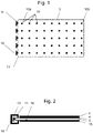
- figure 1 shows schematically a flat light guide 3 for the backlighting of a door center panel of the size 500 mm x 200 mm.
- Five light-emitting diodes (light-emitting diodes, LEDs) 12 are provided on an edge 13 for coupling in light, which couple in color-changeable light via coupling points 11 .
- the specific number of LEDs 12 and coupling points 11 depends on the width of the light guide 3, the desired maximum luminosity and the luminosity of the individual LEDs 12 and can be dimensioned accordingly.
- the surface of the light guide 3 is treated in order to ensure that the light is emitted from the light guide 3 in a uniform and directed manner.
- the surface has indentations 10 which are arranged in a line from the coupling point at the edge 13 to the start of the light guide 3 up to the end of the light guide 3 .
- the first notch 10a has a smaller diameter than the last notch 10b.
- other means can also be used here to set the relative proportion of the decoupled light in the total light that passes the decoupling point so that the proportion is small at the beginning of the light guide 3 and large at the end of the light guide 3 .
- figure 2 shows schematically the cross section of the device with the light guide 3, in which via the coupling point 11 located in a housing 14 RGB LED 12 light is coupled.
- An optical lacquer layer 4 is applied to the entire surface of the light guide 3, to which a covering element 6 is attached.
- the notch 10 is introduced in such a way that a quantity of light dependent on the diameter of the notch 10 is coupled out and emitted in the direction of the cover element 6.
- a reflection layer 15 is attached to the opposite side of the light guide 3 .
- the reflection layer 15 reflects light refracted in the direction of the reflection layer 15 back to the side of the light outcoupling.
- the Reflective layer 15 can also be formed by an optical lacquer, with the reflective effect being less.
- figure 3 shows a schematic layer structure, which is not part of the invention.
- the representation is blown open, there are no gaps between the layers 8, 9, 7, 5, 4, 3, 15.
- the light guide 3 is covered on the side facing away from the light decoupling by a reflection layer 15, while on the side of the light decoupling a an optical lacquer existing lacquer layer 4 is applied.
- the layer thickness of the light guide 3 is approximately 2 mm, and that of the optical lacquer is 10 ⁇ m.
- the lacquer layer 4 must be at least 1 ⁇ m thick in order to ensure sufficient reflection; layer thicknesses of 8-12 ⁇ m are advantageous for process and tolerance reasons.
- the refractive index of the lacquer layer 4 is matched to the light guide 3 and must be smaller than that of the plastic from which the light guide 3 is made. If polymethyl methacrylate PMMA is used, the refractive index of the lacquer layer 4 should be less than 1.49. If polycarbonate PC with a refractive index of approximately 1.57 is used as the light guide 3, the refractive index of the lacquer layer 4 should be correspondingly lower than the specific refractive index of the PC, ie in the range of up to 1.56.
- the lacquer layer 4 covers the light guide 3 on the entire surface, including the narrow sides (this is not absolutely necessary), but not on the side of the reflection layer 15. If a reflection layer 15 is to be glued on as a film, this side can also be lacquered. Alternatively, the lacquer layer 4 only covers the Points of the light guide 3 that are sensitive to dirt or are needed to attach the cover element 6 consisting of a spacer fabric 7 and a lamination 8 .
- the spacer fabric 7 has a thickness of a few millimeters in order to produce a soft surface of the cover part 6 that can be pressed in. A structure without a spacer fabric 7, ie hard-laminated, is also possible. The other layer thicknesses are significantly smaller.
- connection between the lacquer layer 4 and the spacer fabric 7 is effected by an adhesive layer 5 .
- a second adhesive layer 9 connects the spacer fabric 7 and the backing layer 8.
- the adhesive layers 5 and 9 are applied to almost the entire surface of the layers 4, 7 and 8 for a robust connection that avoids air pockets.
- the Alexit HighGloss Clearcoat 460-13 from Mankiewicz is suitable as an adhesive.
- FIG. 1 shows an interior equipment 1 of a vehicle with the attached device for lighting, which is not part of the invention.
- the light guide 3 has a T-structure, with the orthogonally protruding ends on the narrow sides of the light guide 3 being used for clamping to the interior trim 1 and the subassembly 2 of a motor vehicle being backlit.
- the spacer fabric 7 follows, which in turn is firmly connected to the laminating layer 8 by a second adhesive layer (not shown).
- the light guide 3 is slightly rounded at the T-ends arranged on the narrow sides, so that these ends can be surrounded by the laminating layer 8 and the device can be positioned without viewing the light guide 3 in allows the interior trim 1 to be clipped in.
- Assembly 2 is a door center panel, see figure 5 .
- the assembly 2 can be inserted into the vehicle door without additional tools.
- the light guide 3 is in Figure 4 and 5 just shown. However, it is also possible to produce desired contours for shaping the interior of the vehicle, ie the light guide 3 can alternatively be more strongly curved and form a three-dimensional surface.
- figure 5 12 shows the same device before it is introduced into the assembly 2.
- the device Toward the interior of the vehicle, the device is covered with the lining layer 8 made of leather or fabric, so that other materials are not visible. This creates a visually appealing surface.
- the surface that is haptically improved by the underlying spacer fabric 7 is also soft and elastically depressible. The device can easily and without much effort be subsequently introduced into the interior 1, so that retrofitting with a backlit cover element is possible.
- figure 6 shows an embodiment of the device according to the invention, which consists of a three-dimensional, flat light guide 3, to which reinforcements and holding elements are additionally attached (not shown).
- the light is coupled in at two coupling points 11, which are introduced as ramps in the surface of the light guide near the bends.
- RGB LEDs 12 are attached to each of these coupling points 11 and couple light into the light guide 3 at an angle that interacts with the light guide applied to the light guide optical lacquer layer 4 lead to reflection at the contact surface of light guide 3 to optical lacquer layer 4.
- a deep-drawn, printed foil 6 with a thickness of approx.
- the film 6 consists of transparent polycarbonate PC or polymethyl methacrylate PMMA. It can also have a thickness of up to 1 mm and can also be printed on the side facing the optical lacquer layer 4, so that a depth effect is achieved.
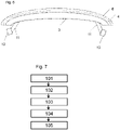
- figure 7 shows a method for manufacturing a device, which is not part of the invention.
- the flat light guide 3 is manufactured by means of injection molding or injection compression molding.
- the surface of the light guide 3 is varnished with an optical varnish 4 by spraying, which then dries out.
- an adhesive 5 is then sprayed onto the optical lacquer 4 and the spacer fabric 7 is applied.
- a second adhesive 9 is then sprayed onto the spacer fabric 7 and the leather is applied as a laminating layer 8 .
- the LEDs 12 are then plugged onto the coupling points 11.
Landscapes
- Engineering & Computer Science (AREA)
- Mechanical Engineering (AREA)
- Arrangements Of Lighting Devices For Vehicle Interiors, Mounting And Supporting Thereof, Circuits Therefore (AREA)
- Physics & Mathematics (AREA)
- General Physics & Mathematics (AREA)
- Optics & Photonics (AREA)
Claims (14)
- Dispositif d'éclairage d'un ensemble (2) d'aménagement intérieur (1) d'un véhicule, le dispositif comprenantun guide de lumière (3) sensiblement bidimensionnel, une couche de peinture optique (4) qui recouvre au moins partiellement le guide de lumière (3) et qui présente un indice de réfraction défini qui contrôle la sortie de faisceaux lumineux au niveau de la surface du guide de lumière (3),une première couche d'adhésif (5) mouillant au moins partiellement la couche de peinture (4),au moins un élément de recouvrement (6) relié à la couche de peinture (4) par la couche d'adhésif (5), l'élément de recouvrement (6) comprenant une feuille emboutie et imprimée.
- Dispositif selon l'une des revendications précédentes, caractérisé en ce que le guide de lumière (3) est moulé par injection ou estampé par injection.
- Dispositif selon l'une des revendications précédentes, caractérisé en ce que le guide de lumière (3) est en polyméthacrylate de méthyle et la couche de peinture (4) a un indice de réfraction inférieur à 1,49.
- Dispositif selon l'une des revendications précédentes, caractérisé en ce que le guide de lumière (3) est en polycarbonate et la couche de peinture (4) a un indice de réfraction inférieur à 1,57.
- Dispositif selon l'une des revendications précédentes, caractérisé en ce que la couche de peinture (4) a une épaisseur > 1 µm, de préférence entre 8 et 12 µm.
- Dispositif selon l'une des revendications précédentes, caractérisé en ce que la couche de peinture (4) est sensiblement transparente dans le domaine spectral visible.
- Dispositif selon l'une des revendications précédentes, caractérisé en ce que la couche de peinture (4) présente une atténuation indépendante de la longueur d'onde.
- Dispositif selon l'une des revendications précédentes, caractérisé en ce que le guide de lumière (3) est pourvu d'une structure de surface (10) destinée à la sortie uniforme de lumière par couplage.
- Dispositif selon la revendication 8, caractérisé en ce que la structure de surface (10) est constituée d'une multiplicité d'encoches ponctuelles (10a, 10b) ou de particules diffusantes (10a, 10b).
- Dispositif selon la revendication 9, caractérisé en ce que les encoches ponctuelles (10a, 10b) augmentent de taille à partir d'un point d'injection par couplage (11).
- Dispositif selon l'une des revendications 1 à 9, caractérisé en ce que l'injection de lumière par couplage dans le guide de lumière est effectuée au moyen de LED (12).
- Dispositif selon la revendication 8, caractérisé en ce qu'une pluralité de points d'injection par couplage (11), qui sont couplés chacun à au moins une LED (12), sont montés le long d'un bord (13) du guide de lumière (3).
- Dispositif selon l'une des revendications précédentes, caractérisé en ce que le guide de lumière (3) est courbe et forme une surface tridimensionnelle qui définit le contour de l'équipement intérieur (1) du véhicule.
- Dispositif selon l'une des revendications précédentes, caractérisé en ce que l'équipement intérieur (1) est une porte de véhicule, un habitacle ou une console centrale.
Applications Claiming Priority (1)
| Application Number | Priority Date | Filing Date | Title |
|---|---|---|---|
| DE102013008433.4A DE102013008433B4 (de) | 2013-05-17 | 2013-05-17 | Flächige Vorrichtung zur Beleuchtung der Innenausstattung eines Fahrzeugs |
Publications (2)
| Publication Number | Publication Date |
|---|---|
| EP2803531A1 EP2803531A1 (fr) | 2014-11-19 |
| EP2803531B1 true EP2803531B1 (fr) | 2022-04-20 |
Family
ID=50639343
Family Applications (1)
| Application Number | Title | Priority Date | Filing Date |
|---|---|---|---|
| EP14167179.2A Active EP2803531B1 (fr) | 2013-05-17 | 2014-05-06 | Dispositif plat destiné à éclairer l'équipement intérieur d'un véhicule |
Country Status (3)
| Country | Link |
|---|---|
| US (1) | US20140340920A1 (fr) |
| EP (1) | EP2803531B1 (fr) |
| DE (1) | DE102013008433B4 (fr) |
Families Citing this family (15)
| Publication number | Priority date | Publication date | Assignee | Title |
|---|---|---|---|---|
| DE102014006490B4 (de) | 2014-05-06 | 2016-04-07 | Lisa Dräxlmaier GmbH | Flächiges Beleuchtungselement für die lnnenausstattung eines Fahrzeugs |
| DE102015104572A1 (de) * | 2015-03-26 | 2016-09-29 | Lisa Dräxlmaier GmbH | Beleuchtungseinrichtung für Flugzeuginnenräume |
| DE102015211803A1 (de) * | 2015-06-25 | 2016-12-29 | Volkswagen Aktiengesellschaft | Beleuchtbares Dekorelement |
| DE102015013669B4 (de) * | 2015-10-23 | 2023-02-09 | Lisa Dräxlmaier GmbH | Hinterleuchtetes Innenausstattungsteil für ein Kraftfahrzeug |
| DE102015120876A1 (de) * | 2015-12-02 | 2017-06-08 | Novem Car Interior Design Gmbh | Formteil, insbesondere als Formteil ausgebildetes Dekorteil und/oder Verkleidungsteil für einen Fahrzeuginnenraum und ein Verfahren zum Herstellen eines Formteils |
| DE102016104113B4 (de) * | 2016-03-07 | 2018-02-15 | Lisa Dräxlmaier GmbH | Flächige beleuchtungseinrichtung für trennwände in flugzeuginnenräumen |
| DE102016009660B4 (de) * | 2016-08-09 | 2021-09-09 | Daimler Ag | Beleuchtetes Zierteil |
| US10637977B1 (en) * | 2016-08-31 | 2020-04-28 | Apple Inc. | Illumination systems for items with leather |
| CN110389468A (zh) * | 2018-04-17 | 2019-10-29 | 宸盛光电有限公司 | 背光模块及其显示装置 |
| FR3086729B1 (fr) * | 2018-09-27 | 2021-04-23 | Psa Automobiles Sa | Guide de lumiere d’un dispositif d’eclairage de vehicule |
| US10807526B2 (en) | 2019-02-14 | 2020-10-20 | Volvo Car Corporation | Vehicle interior lighting system |
| US20220236472A1 (en) * | 2019-02-22 | 2022-07-28 | Vuzix Corporation | Parallel plate waveguides |
| DE102019003359A1 (de) * | 2019-05-13 | 2020-11-19 | Daimler Ag | Luftausströmer für ein Fahrzeug |
| DE102021121853B4 (de) | 2021-08-24 | 2025-12-31 | Lisa Dräxlmaier GmbH | Beleuchtungseinrichtung sowie verfahren zum herstellen einer beleuchtungseinrichtung |
| DE102022112949A1 (de) | 2022-05-23 | 2023-11-23 | HELLA GmbH & Co. KGaA | Beleuchtungsvorrichtung und Verfahren zu deren Herstellung |
Citations (3)
| Publication number | Priority date | Publication date | Assignee | Title |
|---|---|---|---|---|
| US3491245A (en) * | 1967-04-10 | 1970-01-20 | George K C Hardesty | Guided light display panel |
| US4277817A (en) * | 1978-06-23 | 1981-07-07 | Blaupunkt-Werke Gmbh | Large-area light source |
| GB2489813A (en) * | 2011-04-08 | 2012-10-10 | Gm Global Tech Operations Inc | An illuminating formed part, especially a decorative covering part for the interior space of a vehicle |
Family Cites Families (23)
| Publication number | Priority date | Publication date | Assignee | Title |
|---|---|---|---|---|
| US3754135A (en) * | 1971-04-21 | 1973-08-21 | C Hulbert | Light treating means |
| GB2267378B (en) * | 1992-05-22 | 1996-07-10 | Nokia Mobile Phones Uk | Illuminated LCD apparatus |
| US5479324A (en) * | 1993-12-17 | 1995-12-26 | Barry; James E. | Illuminated gas tank or shell |
| JPH0868910A (ja) * | 1994-08-29 | 1996-03-12 | Enplas Corp | 面光源装置用導光板及びその製造方法 |
| JP3090245B2 (ja) * | 1994-11-18 | 2000-09-18 | 河西工業株式会社 | 自動車用内装部品及びその製造方法 |
| US5858159A (en) * | 1995-04-25 | 1999-01-12 | Hoover Universal, Inc. | Method for manufacturing automotive seat assemblies using pre-bonded adhesives |
| EP0879991A3 (fr) * | 1997-05-13 | 1999-04-21 | Matsushita Electric Industrial Co., Ltd. | Système d'illumination |
| JP4298068B2 (ja) * | 1998-08-18 | 2009-07-15 | セイコーエプソン株式会社 | 電気光学装置およびそれらを備えた電子機器並びに電気光学装置の製造方法 |
| KR20010074133A (ko) * | 2001-03-30 | 2001-08-04 | 고경진 | 백라이트용 도광판 |
| DK200101287A (da) * | 2001-08-31 | 2003-03-01 | Bang & Olufsen As | Udlæsningsenhed og fremgangsmåde til dens fremstilling |
| CN1849535A (zh) * | 2003-09-08 | 2006-10-18 | 皇家飞利浦电子股份有限公司 | 日光发射板 |
| EP1577166B1 (fr) * | 2004-02-18 | 2010-12-01 | Grammer Ag | Procédé de fabrication d'un revêtement en forme de peau, en particulier pour garniture de véhicules automobiles. |
| DE102005018212A1 (de) * | 2005-04-20 | 2006-10-26 | Hella Kgaa Hueck & Co. | Signalleuchte für Fahrzeuge |
| KR100770602B1 (ko) * | 2005-12-30 | 2007-10-29 | 서울반도체 주식회사 | 광가이드 디바이스 및 이를 포함하는 lcd용 백라이팅모듈 |
| FR2912095B1 (fr) * | 2007-02-01 | 2009-09-18 | Faurecia Interieur Ind Snc | Element a motif decoratif lumineux,et piece d'habillage interieur d'automobile le comportant |
| EP2028046A1 (fr) * | 2007-08-22 | 2009-02-25 | CCL Design GmbH | Corps de décoration |
| EP2028048B1 (fr) * | 2007-08-22 | 2011-04-27 | CCL Design GmbH | Corps de décoration doté d'éléments de décoration pouvant être éclairés |
| DE502007001930D1 (de) * | 2007-11-15 | 2009-12-17 | Novem Car Interior Design Gmbh | Leuchtendes Formteil, ausgebildet als Verkleidungsteil für den Fahrzeuginnenraum |
| JP4969544B2 (ja) * | 2008-09-19 | 2012-07-04 | 本田技研工業株式会社 | 照明部材及びそれを用いたドアライニング |
| DE102009000605A1 (de) * | 2009-02-04 | 2010-08-19 | Lisa Dräxlmaier GmbH | Hinterleuchtete genarbte Planware |
| DE102011082343B4 (de) * | 2011-09-08 | 2015-04-09 | Lisa Dräxlmaier GmbH | Dekorverbund mit einer Dekorschicht und einer Licht leitenden Schicht |
| US9533615B2 (en) * | 2011-12-15 | 2017-01-03 | Toyota Motor Engineering & Manufacturing North America, Inc. | Door trim pull cup ambient light |
| DE102012215801A1 (de) | 2012-09-06 | 2014-03-06 | Lisa Dräxlmaier GmbH | Künstliche Formhaut mit integriertem Lichtleiter |
-
2013
- 2013-05-17 DE DE102013008433.4A patent/DE102013008433B4/de not_active Expired - Fee Related
-
2014
- 2014-05-06 EP EP14167179.2A patent/EP2803531B1/fr active Active
- 2014-05-16 US US14/279,613 patent/US20140340920A1/en not_active Abandoned
Patent Citations (3)
| Publication number | Priority date | Publication date | Assignee | Title |
|---|---|---|---|---|
| US3491245A (en) * | 1967-04-10 | 1970-01-20 | George K C Hardesty | Guided light display panel |
| US4277817A (en) * | 1978-06-23 | 1981-07-07 | Blaupunkt-Werke Gmbh | Large-area light source |
| GB2489813A (en) * | 2011-04-08 | 2012-10-10 | Gm Global Tech Operations Inc | An illuminating formed part, especially a decorative covering part for the interior space of a vehicle |
Also Published As
| Publication number | Publication date |
|---|---|
| EP2803531A1 (fr) | 2014-11-19 |
| US20140340920A1 (en) | 2014-11-20 |
| DE102013008433B4 (de) | 2020-12-03 |
| DE102013008433A1 (de) | 2014-11-20 |
Similar Documents
| Publication | Publication Date | Title |
|---|---|---|
| DE102013008433B4 (de) | Flächige Vorrichtung zur Beleuchtung der Innenausstattung eines Fahrzeugs | |
| EP3068653B1 (fr) | Dispositif d'affichage d'au moins un symbole, et procédé de fabrication d'un dispositif d'affichage d'au moins un symbole | |
| EP3140097B1 (fr) | Corps multicouche et procédé de fabrication de celui-ci | |
| DE102014112470B4 (de) | Ausstattungsteil mit leuchtender sichtseite | |
| EP2942233B1 (fr) | Élément d'éclairage plat pour l'équipement intérieur d'un véhicule | |
| DE102011016420A1 (de) | Innenraumbeleuchtung für ein Fahrzeug, Verfahren zur Bereitstellung der Innenraumbeleuchtung im Fahrzeug sowie Fahrzeug mit der Innenraumbeleuchtung | |
| DE102009031820A1 (de) | Kraftfahrzeug-Innenauskleidungsteil mit Lichtleiter | |
| DE102012105412A1 (de) | Beleuchtbares Verkleidungsbauteil für ein Fahrzeug und Verfahren zu dessen Herstellung | |
| DE102018123473A1 (de) | Dekorfolie, Transferfolie, Verwendung einer Transferfolie, Verfahren zur Herstellung einer Transferfolie, Verfahren zum Dekorieren eines Kunststoffformteils sowie Kunststoffformteil | |
| DE102011016396A1 (de) | Dekorformteil für den Innenraum eines Fahrzeugs sowie Innenraumverkleidung mit dem Dekorformteil | |
| DE102008055865A1 (de) | Taster zum Bedienen eines elektrischen Verbrauchers in einem Fahrzeug, insbesondere zur Integration in einem Zierteil | |
| DE102013021600A1 (de) | Flächenleuchte | |
| DE102015003207A1 (de) | Ziervorrichtung für ein Kraftfahrzeug | |
| DE102019207066B4 (de) | Bedienvorrichtung für ein Kraftfahrzeug sowie Verfahren zur Herstellung der Bedienvorrichtung | |
| DE102010051307A1 (de) | Anzeigeelement | |
| EP3631291B1 (fr) | Élément guide de lumière décoratif | |
| DE102019109740A1 (de) | Fahrzeugfensterscheibeneinrichtung und Verfahren zum Betreiben einer Fahrzeugfensterscheibeneinrichtung | |
| DE102012003412A1 (de) | Hinterleuchtetes Formteil und dessen Herstellungsverfahren | |
| DE102012211821A1 (de) | Leuchteneinheit für ein Kraftfahrzeug und Verfahren zum Herstellen eines Gehäuseelementes einer Leuchteneinheit für ein Kraftfahrzeug | |
| EP3702144A1 (fr) | Matière de revêtement en plastique | |
| EP3792111A1 (fr) | Luminaire | |
| DE102011016398A1 (de) | Verkleidungselement für den Innenraum eines Fahrzeugs sowie Fahrzeuginnenausstattung mit dem Verkleidungselement | |
| DE102019109742A1 (de) | Fahrzeugfensterscheibeneinrichtung und Verfahren zum Betreiben einer Fahrzeugfensterscheibeneinrichtung | |
| DE102011016400A1 (de) | Seitenspiegel für ein Fahrzeug | |
| DE102023000269A1 (de) | Beleuchtbarer Dekormehrschichtverbund, Anbauteil für ein Fahrzeug sowie Fahrzeug |
Legal Events
| Date | Code | Title | Description |
|---|---|---|---|
| PUAI | Public reference made under article 153(3) epc to a published international application that has entered the european phase |
Free format text: ORIGINAL CODE: 0009012 |
|
| 17P | Request for examination filed |
Effective date: 20140506 |
|
| AK | Designated contracting states |
Kind code of ref document: A1 Designated state(s): AL AT BE BG CH CY CZ DE DK EE ES FI FR GB GR HR HU IE IS IT LI LT LU LV MC MK MT NL NO PL PT RO RS SE SI SK SM TR |
|
| AX | Request for extension of the european patent |
Extension state: BA ME |
|
| R17P | Request for examination filed (corrected) |
Effective date: 20150512 |
|
| RBV | Designated contracting states (corrected) |
Designated state(s): AL AT BE BG CH CY CZ DE DK EE ES FI FR GB GR HR HU IE IS IT LI LT LU LV MC MK MT NL NO PL PT RO RS SE SI SK SM TR |
|
| TPAC | Observations filed by third parties |
Free format text: ORIGINAL CODE: EPIDOSNTIPA |
|
| STAA | Information on the status of an ep patent application or granted ep patent |
Free format text: STATUS: EXAMINATION IS IN PROGRESS |
|
| 17Q | First examination report despatched |
Effective date: 20200430 |
|
| TPAC | Observations filed by third parties |
Free format text: ORIGINAL CODE: EPIDOSNTIPA |
|
| TPAC | Observations filed by third parties |
Free format text: ORIGINAL CODE: EPIDOSNTIPA |
|
| REG | Reference to a national code |
Ref country code: DE Ref legal event code: R079 Ref document number: 502014016202 Country of ref document: DE Free format text: PREVIOUS MAIN CLASS: B60Q0003020000 Ipc: B60Q0003540000 |
|
| GRAP | Despatch of communication of intention to grant a patent |
Free format text: ORIGINAL CODE: EPIDOSNIGR1 |
|
| STAA | Information on the status of an ep patent application or granted ep patent |
Free format text: STATUS: GRANT OF PATENT IS INTENDED |
|
| RIC1 | Information provided on ipc code assigned before grant |
Ipc: G02B 6/00 20060101ALN20211216BHEP Ipc: B60Q 3/64 20170101ALI20211216BHEP Ipc: B60Q 3/62 20170101ALI20211216BHEP Ipc: B60Q 3/54 20170101AFI20211216BHEP |
|
| INTG | Intention to grant announced |
Effective date: 20220107 |
|
| RIC1 | Information provided on ipc code assigned before grant |
Ipc: G02B 6/00 20060101ALN20211221BHEP Ipc: B60Q 3/64 20170101ALI20211221BHEP Ipc: B60Q 3/62 20170101ALI20211221BHEP Ipc: B60Q 3/54 20170101AFI20211221BHEP |
|
| GRAS | Grant fee paid |
Free format text: ORIGINAL CODE: EPIDOSNIGR3 |
|
| GRAA | (expected) grant |
Free format text: ORIGINAL CODE: 0009210 |
|
| STAA | Information on the status of an ep patent application or granted ep patent |
Free format text: STATUS: THE PATENT HAS BEEN GRANTED |
|
| AK | Designated contracting states |
Kind code of ref document: B1 Designated state(s): AL AT BE BG CH CY CZ DE DK EE ES FI FR GB GR HR HU IE IS IT LI LT LU LV MC MK MT NL NO PL PT RO RS SE SI SK SM TR |
|
| REG | Reference to a national code |
Ref country code: GB Ref legal event code: FG4D Free format text: NOT ENGLISH |
|
| REG | Reference to a national code |
Ref country code: CH Ref legal event code: EP |
|
| REG | Reference to a national code |
Ref country code: IE Ref legal event code: FG4D Free format text: LANGUAGE OF EP DOCUMENT: GERMAN |
|
| REG | Reference to a national code |
Ref country code: DE Ref legal event code: R096 Ref document number: 502014016202 Country of ref document: DE |
|
| REG | Reference to a national code |
Ref country code: AT Ref legal event code: REF Ref document number: 1484936 Country of ref document: AT Kind code of ref document: T Effective date: 20220515 |
|
| REG | Reference to a national code |
Ref country code: LT Ref legal event code: MG9D |
|
| REG | Reference to a national code |
Ref country code: NL Ref legal event code: MP Effective date: 20220420 |
|
| PG25 | Lapsed in a contracting state [announced via postgrant information from national office to epo] |
Ref country code: NL Free format text: LAPSE BECAUSE OF FAILURE TO SUBMIT A TRANSLATION OF THE DESCRIPTION OR TO PAY THE FEE WITHIN THE PRESCRIBED TIME-LIMIT Effective date: 20220420 |
|
| PG25 | Lapsed in a contracting state [announced via postgrant information from national office to epo] |
Ref country code: SE Free format text: LAPSE BECAUSE OF FAILURE TO SUBMIT A TRANSLATION OF THE DESCRIPTION OR TO PAY THE FEE WITHIN THE PRESCRIBED TIME-LIMIT Effective date: 20220420 Ref country code: PT Free format text: LAPSE BECAUSE OF FAILURE TO SUBMIT A TRANSLATION OF THE DESCRIPTION OR TO PAY THE FEE WITHIN THE PRESCRIBED TIME-LIMIT Effective date: 20220822 Ref country code: NO Free format text: LAPSE BECAUSE OF FAILURE TO SUBMIT A TRANSLATION OF THE DESCRIPTION OR TO PAY THE FEE WITHIN THE PRESCRIBED TIME-LIMIT Effective date: 20220720 Ref country code: LT Free format text: LAPSE BECAUSE OF FAILURE TO SUBMIT A TRANSLATION OF THE DESCRIPTION OR TO PAY THE FEE WITHIN THE PRESCRIBED TIME-LIMIT Effective date: 20220420 Ref country code: HR Free format text: LAPSE BECAUSE OF FAILURE TO SUBMIT A TRANSLATION OF THE DESCRIPTION OR TO PAY THE FEE WITHIN THE PRESCRIBED TIME-LIMIT Effective date: 20220420 Ref country code: GR Free format text: LAPSE BECAUSE OF FAILURE TO SUBMIT A TRANSLATION OF THE DESCRIPTION OR TO PAY THE FEE WITHIN THE PRESCRIBED TIME-LIMIT Effective date: 20220721 Ref country code: FI Free format text: LAPSE BECAUSE OF FAILURE TO SUBMIT A TRANSLATION OF THE DESCRIPTION OR TO PAY THE FEE WITHIN THE PRESCRIBED TIME-LIMIT Effective date: 20220420 Ref country code: ES Free format text: LAPSE BECAUSE OF FAILURE TO SUBMIT A TRANSLATION OF THE DESCRIPTION OR TO PAY THE FEE WITHIN THE PRESCRIBED TIME-LIMIT Effective date: 20220420 Ref country code: BG Free format text: LAPSE BECAUSE OF FAILURE TO SUBMIT A TRANSLATION OF THE DESCRIPTION OR TO PAY THE FEE WITHIN THE PRESCRIBED TIME-LIMIT Effective date: 20220720 |
|
| PG25 | Lapsed in a contracting state [announced via postgrant information from national office to epo] |
Ref country code: RS Free format text: LAPSE BECAUSE OF FAILURE TO SUBMIT A TRANSLATION OF THE DESCRIPTION OR TO PAY THE FEE WITHIN THE PRESCRIBED TIME-LIMIT Effective date: 20220420 Ref country code: PL Free format text: LAPSE BECAUSE OF FAILURE TO SUBMIT A TRANSLATION OF THE DESCRIPTION OR TO PAY THE FEE WITHIN THE PRESCRIBED TIME-LIMIT Effective date: 20220420 Ref country code: LV Free format text: LAPSE BECAUSE OF FAILURE TO SUBMIT A TRANSLATION OF THE DESCRIPTION OR TO PAY THE FEE WITHIN THE PRESCRIBED TIME-LIMIT Effective date: 20220420 Ref country code: IS Free format text: LAPSE BECAUSE OF FAILURE TO SUBMIT A TRANSLATION OF THE DESCRIPTION OR TO PAY THE FEE WITHIN THE PRESCRIBED TIME-LIMIT Effective date: 20220820 |
|
| REG | Reference to a national code |
Ref country code: CH Ref legal event code: PL |
|
| REG | Reference to a national code |
Ref country code: DE Ref legal event code: R097 Ref document number: 502014016202 Country of ref document: DE |
|
| REG | Reference to a national code |
Ref country code: BE Ref legal event code: MM Effective date: 20220531 |
|
| PG25 | Lapsed in a contracting state [announced via postgrant information from national office to epo] |
Ref country code: LI Free format text: LAPSE BECAUSE OF NON-PAYMENT OF DUE FEES Effective date: 20220531 Ref country code: EE Free format text: LAPSE BECAUSE OF FAILURE TO SUBMIT A TRANSLATION OF THE DESCRIPTION OR TO PAY THE FEE WITHIN THE PRESCRIBED TIME-LIMIT Effective date: 20220420 Ref country code: DK Free format text: LAPSE BECAUSE OF FAILURE TO SUBMIT A TRANSLATION OF THE DESCRIPTION OR TO PAY THE FEE WITHIN THE PRESCRIBED TIME-LIMIT Effective date: 20220420 Ref country code: CZ Free format text: LAPSE BECAUSE OF FAILURE TO SUBMIT A TRANSLATION OF THE DESCRIPTION OR TO PAY THE FEE WITHIN THE PRESCRIBED TIME-LIMIT Effective date: 20220420 Ref country code: CH Free format text: LAPSE BECAUSE OF NON-PAYMENT OF DUE FEES Effective date: 20220531 Ref country code: SM Free format text: LAPSE BECAUSE OF FAILURE TO SUBMIT A TRANSLATION OF THE DESCRIPTION OR TO PAY THE FEE WITHIN THE PRESCRIBED TIME-LIMIT Effective date: 20220420 Ref country code: SK Free format text: LAPSE BECAUSE OF FAILURE TO SUBMIT A TRANSLATION OF THE DESCRIPTION OR TO PAY THE FEE WITHIN THE PRESCRIBED TIME-LIMIT Effective date: 20220420 Ref country code: RO Free format text: LAPSE BECAUSE OF FAILURE TO SUBMIT A TRANSLATION OF THE DESCRIPTION OR TO PAY THE FEE WITHIN THE PRESCRIBED TIME-LIMIT Effective date: 20220420 Ref country code: MC Free format text: LAPSE BECAUSE OF FAILURE TO SUBMIT A TRANSLATION OF THE DESCRIPTION OR TO PAY THE FEE WITHIN THE PRESCRIBED TIME-LIMIT Effective date: 20220420 Ref country code: LU Free format text: LAPSE BECAUSE OF NON-PAYMENT OF DUE FEES Effective date: 20220506 |
|
| PLBE | No opposition filed within time limit |
Free format text: ORIGINAL CODE: 0009261 |
|
| STAA | Information on the status of an ep patent application or granted ep patent |
Free format text: STATUS: NO OPPOSITION FILED WITHIN TIME LIMIT |
|
| 26N | No opposition filed |
Effective date: 20230123 |
|
| PG25 | Lapsed in a contracting state [announced via postgrant information from national office to epo] |
Ref country code: AL Free format text: LAPSE BECAUSE OF FAILURE TO SUBMIT A TRANSLATION OF THE DESCRIPTION OR TO PAY THE FEE WITHIN THE PRESCRIBED TIME-LIMIT Effective date: 20220420 |
|
| PG25 | Lapsed in a contracting state [announced via postgrant information from national office to epo] |
Ref country code: IE Free format text: LAPSE BECAUSE OF NON-PAYMENT OF DUE FEES Effective date: 20220506 |
|
| PG25 | Lapsed in a contracting state [announced via postgrant information from national office to epo] |
Ref country code: SI Free format text: LAPSE BECAUSE OF FAILURE TO SUBMIT A TRANSLATION OF THE DESCRIPTION OR TO PAY THE FEE WITHIN THE PRESCRIBED TIME-LIMIT Effective date: 20220420 Ref country code: BE Free format text: LAPSE BECAUSE OF NON-PAYMENT OF DUE FEES Effective date: 20220531 |
|
| REG | Reference to a national code |
Ref country code: AT Ref legal event code: MM01 Ref document number: 1484936 Country of ref document: AT Kind code of ref document: T Effective date: 20220506 |
|
| PG25 | Lapsed in a contracting state [announced via postgrant information from national office to epo] |
Ref country code: AT Free format text: LAPSE BECAUSE OF NON-PAYMENT OF DUE FEES Effective date: 20220506 |
|
| P01 | Opt-out of the competence of the unified patent court (upc) registered |
Effective date: 20231017 |
|
| PG25 | Lapsed in a contracting state [announced via postgrant information from national office to epo] |
Ref country code: IT Free format text: LAPSE BECAUSE OF FAILURE TO SUBMIT A TRANSLATION OF THE DESCRIPTION OR TO PAY THE FEE WITHIN THE PRESCRIBED TIME-LIMIT Effective date: 20220420 |
|
| PG25 | Lapsed in a contracting state [announced via postgrant information from national office to epo] |
Ref country code: HU Free format text: LAPSE BECAUSE OF FAILURE TO SUBMIT A TRANSLATION OF THE DESCRIPTION OR TO PAY THE FEE WITHIN THE PRESCRIBED TIME-LIMIT; INVALID AB INITIO Effective date: 20140506 |
|
| PG25 | Lapsed in a contracting state [announced via postgrant information from national office to epo] |
Ref country code: MK Free format text: LAPSE BECAUSE OF FAILURE TO SUBMIT A TRANSLATION OF THE DESCRIPTION OR TO PAY THE FEE WITHIN THE PRESCRIBED TIME-LIMIT Effective date: 20220420 Ref country code: CY Free format text: LAPSE BECAUSE OF FAILURE TO SUBMIT A TRANSLATION OF THE DESCRIPTION OR TO PAY THE FEE WITHIN THE PRESCRIBED TIME-LIMIT Effective date: 20220420 |
|
| PG25 | Lapsed in a contracting state [announced via postgrant information from national office to epo] |
Ref country code: MT Free format text: LAPSE BECAUSE OF FAILURE TO SUBMIT A TRANSLATION OF THE DESCRIPTION OR TO PAY THE FEE WITHIN THE PRESCRIBED TIME-LIMIT Effective date: 20220420 |
|
| PG25 | Lapsed in a contracting state [announced via postgrant information from national office to epo] |
Ref country code: BG Free format text: LAPSE BECAUSE OF FAILURE TO SUBMIT A TRANSLATION OF THE DESCRIPTION OR TO PAY THE FEE WITHIN THE PRESCRIBED TIME-LIMIT Effective date: 20220420 |
|
| PG25 | Lapsed in a contracting state [announced via postgrant information from national office to epo] |
Ref country code: BG Free format text: LAPSE BECAUSE OF FAILURE TO SUBMIT A TRANSLATION OF THE DESCRIPTION OR TO PAY THE FEE WITHIN THE PRESCRIBED TIME-LIMIT Effective date: 20220420 |
|
| PGFP | Annual fee paid to national office [announced via postgrant information from national office to epo] |
Ref country code: FR Payment date: 20250310 Year of fee payment: 12 |
|
| PGFP | Annual fee paid to national office [announced via postgrant information from national office to epo] |
Ref country code: GB Payment date: 20250313 Year of fee payment: 12 |
|
| PGFP | Annual fee paid to national office [announced via postgrant information from national office to epo] |
Ref country code: DE Payment date: 20250530 Year of fee payment: 12 |
|
| PG25 | Lapsed in a contracting state [announced via postgrant information from national office to epo] |
Ref country code: TR Free format text: LAPSE BECAUSE OF FAILURE TO SUBMIT A TRANSLATION OF THE DESCRIPTION OR TO PAY THE FEE WITHIN THE PRESCRIBED TIME-LIMIT Effective date: 20220420 |