EP2803532B1 - Dispositif de miroir pour véhicules à moteur - Google Patents
Dispositif de miroir pour véhicules à moteur Download PDFInfo
- Publication number
- EP2803532B1 EP2803532B1 EP13168243.7A EP13168243A EP2803532B1 EP 2803532 B1 EP2803532 B1 EP 2803532B1 EP 13168243 A EP13168243 A EP 13168243A EP 2803532 B1 EP2803532 B1 EP 2803532B1
- Authority
- EP
- European Patent Office
- Prior art keywords
- mirror device
- lens
- cover
- outer housing
- area
- Prior art date
- Legal status (The legal status is an assumption and is not a legal conclusion. Google has not performed a legal analysis and makes no representation as to the accuracy of the status listed.)
- Active
Links
Images
Classifications
-
- F—MECHANICAL ENGINEERING; LIGHTING; HEATING; WEAPONS; BLASTING
- F21—LIGHTING
- F21S—NON-PORTABLE LIGHTING DEVICES; SYSTEMS THEREOF; VEHICLE LIGHTING DEVICES SPECIALLY ADAPTED FOR VEHICLE EXTERIORS
- F21S43/00—Signalling devices specially adapted for vehicle exteriors, e.g. brake lamps, direction indicator lights or reversing lights
- F21S43/10—Signalling devices specially adapted for vehicle exteriors, e.g. brake lamps, direction indicator lights or reversing lights characterised by the light source
- F21S43/13—Signalling devices specially adapted for vehicle exteriors, e.g. brake lamps, direction indicator lights or reversing lights characterised by the light source characterised by the type of light source
- F21S43/14—Light emitting diodes [LED]
-
- B—PERFORMING OPERATIONS; TRANSPORTING
- B60—VEHICLES IN GENERAL
- B60Q—ARRANGEMENT OF SIGNALLING OR LIGHTING DEVICES, THE MOUNTING OR SUPPORTING THEREOF OR CIRCUITS THEREFOR, FOR VEHICLES IN GENERAL
- B60Q1/00—Arrangement of optical signalling or lighting devices, the mounting or supporting thereof or circuits therefor
- B60Q1/26—Arrangement of optical signalling or lighting devices, the mounting or supporting thereof or circuits therefor the devices being primarily intended to indicate the vehicle, or parts thereof, or to give signals, to other traffic
- B60Q1/2661—Arrangement of optical signalling or lighting devices, the mounting or supporting thereof or circuits therefor the devices being primarily intended to indicate the vehicle, or parts thereof, or to give signals, to other traffic mounted on parts having other functions
- B60Q1/2665—Arrangement of optical signalling or lighting devices, the mounting or supporting thereof or circuits therefor the devices being primarily intended to indicate the vehicle, or parts thereof, or to give signals, to other traffic mounted on parts having other functions on rear-view mirrors
-
- B—PERFORMING OPERATIONS; TRANSPORTING
- B60—VEHICLES IN GENERAL
- B60R—VEHICLES, VEHICLE FITTINGS, OR VEHICLE PARTS, NOT OTHERWISE PROVIDED FOR
- B60R1/00—Optical viewing arrangements; Real-time viewing arrangements for drivers or passengers using optical image capturing systems, e.g. cameras or video systems specially adapted for use in or on vehicles
- B60R1/12—Mirror assemblies combined with other articles, e.g. clocks
- B60R1/1207—Mirror assemblies combined with other articles, e.g. clocks with lamps; with turn indicators
-
- F—MECHANICAL ENGINEERING; LIGHTING; HEATING; WEAPONS; BLASTING
- F21—LIGHTING
- F21S—NON-PORTABLE LIGHTING DEVICES; SYSTEMS THEREOF; VEHICLE LIGHTING DEVICES SPECIALLY ADAPTED FOR VEHICLE EXTERIORS
- F21S43/00—Signalling devices specially adapted for vehicle exteriors, e.g. brake lamps, direction indicator lights or reversing lights
- F21S43/20—Signalling devices specially adapted for vehicle exteriors, e.g. brake lamps, direction indicator lights or reversing lights characterised by refractors, transparent cover plates, light guides or filters
- F21S43/235—Light guides
- F21S43/236—Light guides characterised by the shape of the light guide
- F21S43/237—Light guides characterised by the shape of the light guide rod-shaped
-
- F—MECHANICAL ENGINEERING; LIGHTING; HEATING; WEAPONS; BLASTING
- F21—LIGHTING
- F21S—NON-PORTABLE LIGHTING DEVICES; SYSTEMS THEREOF; VEHICLE LIGHTING DEVICES SPECIALLY ADAPTED FOR VEHICLE EXTERIORS
- F21S43/00—Signalling devices specially adapted for vehicle exteriors, e.g. brake lamps, direction indicator lights or reversing lights
- F21S43/20—Signalling devices specially adapted for vehicle exteriors, e.g. brake lamps, direction indicator lights or reversing lights characterised by refractors, transparent cover plates, light guides or filters
- F21S43/235—Light guides
- F21S43/242—Light guides characterised by the emission area
- F21S43/245—Light guides characterised by the emission area emitting light from one or more of its major surfaces
-
- F—MECHANICAL ENGINEERING; LIGHTING; HEATING; WEAPONS; BLASTING
- F21—LIGHTING
- F21S—NON-PORTABLE LIGHTING DEVICES; SYSTEMS THEREOF; VEHICLE LIGHTING DEVICES SPECIALLY ADAPTED FOR VEHICLE EXTERIORS
- F21S43/00—Signalling devices specially adapted for vehicle exteriors, e.g. brake lamps, direction indicator lights or reversing lights
- F21S43/20—Signalling devices specially adapted for vehicle exteriors, e.g. brake lamps, direction indicator lights or reversing lights characterised by refractors, transparent cover plates, light guides or filters
- F21S43/235—Light guides
- F21S43/247—Light guides with a single light source being coupled into the light guide
-
- B—PERFORMING OPERATIONS; TRANSPORTING
- B60—VEHICLES IN GENERAL
- B60Q—ARRANGEMENT OF SIGNALLING OR LIGHTING DEVICES, THE MOUNTING OR SUPPORTING THEREOF OR CIRCUITS THEREFOR, FOR VEHICLES IN GENERAL
- B60Q1/00—Arrangement of optical signalling or lighting devices, the mounting or supporting thereof or circuits therefor
- B60Q1/26—Arrangement of optical signalling or lighting devices, the mounting or supporting thereof or circuits therefor the devices being primarily intended to indicate the vehicle, or parts thereof, or to give signals, to other traffic
- B60Q1/50—Arrangement of optical signalling or lighting devices, the mounting or supporting thereof or circuits therefor the devices being primarily intended to indicate the vehicle, or parts thereof, or to give signals, to other traffic for indicating other intentions or conditions, e.g. request for waiting or overtaking
Definitions
- the present disclosure relates to mirror devices for motor vehicles.
- mirror devices for motor vehicles are increasingly incorporating more technical features and functions apart from the rear view function, such as LEDs in turn signal indicators and in day running lights, sensing means, cameras, antennae, etc.
- document US7195385 discloses an exterior rear view mirror for motor vehicles with an auxiliary turn signal.
- One wall of the mirror housing is made of a transparent plastic material in the area in which the light emitted by the vehicle light is to pass to the exterior.
- This area is painted with a paint of a matching colour such that the vehicle light arranged within the mirror head cannot be recognized from the exterior but the light emitted by it can penetrate to the exterior to a satisfactory degree.
- US2001055214 discloses a rear view mirror device provided with a transparent or semi-transparent casing having a coating layer applied thereon. At least a light-transmissible portion is formed on the casing by removing a predetermined portion of the coating layer on the casing. A light source is provided within the casing for generating light to be emitted from the light-transmissible portion to the outside of the casing, allowing the rear-view mirror device to serve as a turning signal.
- the casing is attached with a cover having a mirror piece enclosing the light source in the casing.
- Document GB2338693 discloses a rear view mirror for motor vehicles comprising a mirror housing for receiving a light source which is activated synchronously with an illuminated film provided outside the housing to produce a flashing light.
- a shield is provided outside the illuminated film for protecting the illuminated film and the light guide and for changing the light emitted by the illuminated film through an appropriate lens.
- Document US2011001428 which corresponds to the preamble of claim 1, shows a rear-view mirror assembly with two or more light modules for emitting corresponding turn signals synchronized with each other.
- the light modules have a transparent or translucent part including at least one outer cover through which the respective light signals exit towards the exterior.
- Document US7396147 refers to a side mirror for motor vehicles comprising a panel which when viewed from one side the panel has a first appearance when not illuminated from the reverse side, but has a second appearance when illuminated from the reverse side. Means are provided for reducing effects upon the panel caused by exposure to ultraviolet radiation.
- US2001055214 discloses a rear-view mirror device including a transparent or semitransparent casting with a coasting layer, a light-transmissible portion formed thereon and a light source within for generating light to be emitted from the light-transmissible portion to the outside of the casing such that the rear-view mirror device acts as a turning signal.
- the provision of such additional technical features and functions in the mirror device results in that the outer mirror casing needs to be redesigned to be adapted to the mounting of the inside parts.
- manufacturers are required to re-mould the casing for the rear view mirror and to produce new designs to suitably house the parts therein. This is cost ineffective and time consuming.
- aerodynamics is adversely affected due to shapes that are required to be adapted for these technical functions and features.
- a mirror device for motor vehicles has been thus devised which has been found that solves or at least mitigates the above technical problems while providing significant advantages as it will be explained further below.
- a mirror device for motor vehicles as defined in claim 1 is disclosed herein.
- Advantageous embodiments are defined in the dependent claims.
- the present mirror device comprises an outer housing that is made of any suitable resistant material adapted for receiving a mirror therein as well as for receiving a number of parts such as illumination elements and electronic related parts as it will be disclosed hereinbelow.
- the outer housing of the present mirror device is suitably designed for being mounted on a motor vehicle. However, other different applications are not ruled out.
- the mirror device is further provided with a cover.
- the cover serves the purpose of covering at least part of the front portion of the outer housing.
- front, rear, side, etc. portions of the outer housing refer to those portions of the outer housing relative to the vehicle.
- the front portion of the mirror device refers herein to one portion that is directed toward the front of the motor vehicle.
- the present mirror device is further provided with a lens.
- the lens may be a molded piece at least part of which is at least substantially transparent.
- the lens is fitted within the outer housing, with at least part of which being arranged behind the cover.
- the present mirror device is also provided with an inner housing substantially covering the lens. This inner housing may be provided with a dark inner background surface that is substantially parallel to that of the mirror.
- Illumination means comprising one or a number of illumination elements are also provided within the outer housing.
- the illumination elements may be one or more LEDs, at least one light guide, at least one light emitting surface or the like, and/or even a combination thereof.
- Illumination elements may emit light directly or indirectly incident on the lens.
- At least one of the illumination elements may be a blinker.
- at least one of said illumination elements may be arranged such that light is directed to the side and/on the rear of the outer housing of the mirror device.
- the lens of the present mirror device has at least two different areas (first and second area) and the cover has at least two different cover elements (first and second cover element) as it will be explained below.
- the first area of the lens is mounted internal to the cover, i.e., behind this. This first area of the lens is such that it allows the light to at least partially pass forward and at least partially pass to the vehicle side.
- a colour modifier filter could be also provided associated with the first area of the lens.
- the second area of the lens in some embodiments extends to at least one side portion of the outer housing.
- This second area of the lens is made of a transparent material. The light is thus allowed to pass through the second area of the lens preferably without altering its colour and with negligible loss light relative to the first area.
- the second area of the lens may also allow light to be directed to the driver if required.
- the first cover element of the cover is external to the lens. Indeed, the first cover element could extend over the entire length of the cover.
- the first cover element is of a nature such that at least one of the above mentioned illumination elements of the illumination means is visible from the exterior of the outer housing when the illumination means are activated, i.e. when the illumination elements are turned on, and such that at least one of the above mentioned illumination elements is not visible from the exterior of the outer housing when the illumination means are not activated, i.e. when the illumination elements are turned off.
- the first cover element of the present mirror device may be provided with a coating with one or more thin films applied by means of a vacuum deposition method, such as for example, through physical vapour deposition (PVD).
- the thin film(s) is/are applied onto the cover of the mirror device through condensation of a vaporized form of the film materials by means of high temperature vacuum evaporation and subsequent condensation, plasma sputter bombardment, etc.
- a wide range of decorative coating finishes can be applied in this way.
- This coating onto the cover makes it possible that visual (optical) information such as side light and blinkers to be provided by the mirror device such that it is only visible when the illumination means are turned on.
- the first cover element is preferably mounted flush with the second area of the lens for the purposes making the assembly compact and with good aerodynamic characteristics. This is made possible due to the two-area-design of the lens such that the first and second areas of the lens lie in different planes.
- the second area of the lens is also mounted flush with the outer housing. This results in a very compact, closed assembly that enhances the aerodynamic characteristics of the mirror device when the vehicle is travelling while reducing noise improving travelling comfort to the user.
- the second cover element is made of a substantially opaque material. It may be overmoulded on the first cover element.
- the second cover element has an overlapping portion that is arranged behind at least one portion of the first cover element. Specifically, this overlapping portion of the second cover element may be sandwiched between at least one portion of the first area of the lens and at least one portion of the first cover element.
- At least the first cover element may be made of a lightweight resistant thermoplastic material that is at least substantially transparent. This material is preferably for example PMMA or the like.
- at least the first cover element may have a colour matching that of the outer housing of the mirror device.
- the present mirror device which combines illumination elements (e.g. turn indicators) that are hidden when turned off together with flush mounted parts, a pleasant aesthetics and enhanced aerodynamic characteristics are obtained.
- illumination elements e.g. turn indicators
- This compact design results in wind noise reduction as there is no joints, grooves or other design discontinuities which improves travelling comfort.
- the two-area-design of the lens allows two light differentiated, independent areas to be provided such that there is no loss in intensity of light.
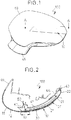
- the example of the present mirror device 100 comprises an outer housing 40 that is suitably adapted for including a number of parts therein such as electrical components like PCBs 50, 55, connectors 60, illumination means 30, 31, etc.
- the outer housing 40 is also adapted for receiving a rear view mirror (not shown) and it is provided with a vehicle mount portion 45.
- An inner housing 41 is also provided within the outer housing 40.
- the inner housing 41 is arranged such that it substantially covers the lens 20 as shown in figures 2-4 .
- the inner housing 41 is provided with a dark inner background surface (not shown) that is substantially parallel to that of the mirror.
- the connectors 60 may be formed integral with the inner housing 41.
- the mirror device 100 of the embodiment shown is further provided with a cover 10.
- the cover 10 serves the purpose of covering at least a part of the front portion of the outer housing 40, that is, the one corresponding to the front portion of the motor vehicle.
- a lens 20 is also provided within the outer housing 40. At least part of the lens 20 is arranged behind the cover 10, as it will be explained further below.
- Illumination means 30, 31 comprising at least one illumination element are also arranged within the outer housing 40.
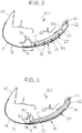
- the arrangement of the illumination means 30, 31 defines several embodiments of the mirror device 100. Three of such embodiments are shown as non-limiting examples in figures 2 , 3 and 4 of the drawings. They will be explained further below.
- the lens 20 in the embodiments shown in figures 2-4 has two different areas.
- a first area 21 of the lens 20 is mounted internal to the cover 10 as shown in figures 2-4 .
- the first area 21 of the lens 20 that is positioned behind the cover 10 is made of a material such that the light emitted from the illumination means 30, 31 is allowed to at least partially pass forward and at least partially pass toward the vehicle side, that is, to a side portion of the outer housing 40.
- This first area 21 of the lens 20 of the mirror device 100 may include a colour modifier filter (not shown in the drawings).
- a second area 22 of the lens 20 extends to at least one side portion of the outer housing 40.
- This second area 22 of the lens 20 is made of a transparent material such that light from the illumination means 30, 31 is allowed to pass through without altering its colour and with negligible loss light relative to the first area 21.
- the second area 22 of the lens 20 may allow light to be directed to the driver as well.
- the cover 10 in the embodiments shown in figures 2-4 has two different cover elements 11, 12, as explained below.
- the first cover element 11 is overmoulded on the second cover element 12.
- the first cover element 11 is made of PMMA or the like and has a colour matching that of the outer housing 40 of the mirror device 100.
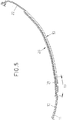
- the first cover element 11 of the cover 10 is external to the lens 20 as shown in figures 2-4 and in more detail in figure 5 .
- the first cover element 11 is of a nature such that the illumination elements 30 are visible from the exterior of the outer housing 40 only when the illumination means are turned on. When the illumination means are turned off, the illumination elements 30 are not visible from the exterior of the outer housing 40.
- PVD physical vapour deposition
- the first area 21 and second area 22 of the lens 20 lie in different planes. This configuration makes it possible that the second area 22 of the lens 20 is mounted flush with the first cover element 11. This advantageously renders the assembly very compact and with enhanced aerodynamic characteristics.
- the second cover element 12 of the cover 10 is made of a substantially opaque material and it is placed behind the first cover element 11 such that an overlapping portion 13 is defined. More specifically, and as shown in figures 2-4 , and more clearly in figure 5 , this overlapping portion 13 of the second cover element 12 is defined between an end portion of the first area 21 of the lens 20 and one portion of the first cover element 11.
- the illumination means of the mirror device 100 include a first set of illumination elements 30 and a second set of illumination elements 31.
- the sets of illumination elements 30, 31 are different and independent from each other although embodiments where the sets of illumination elements 30, 31 are dependent on each other are not ruled out.
- the first set of illumination elements comprises a light guide 30 that is connected to a PCB 50.
- the light guide 30 extends substantially along the first area 21 of the lens 20 as shown in figure 2 of the drawings.
- the second set of illumination elements comprises a LED 31.
- the LED 31 is provided such that light is incident on the second area 22 of the lens 20.
- LED 31 is connected to a corresponding PCB 55.
- the PCB 55 of the LED 31 is arranged inclined within the outer housing 40 such that light is directed to side and rear portions of the outer housing 40.
- the illumination means comprise a first set of illumination elements 30 and a second set of illumination elements 31.
- both the first and the second sets of illumination elements 30, 31 comprise LEDs.
- the first set of illumination elements comprises a number of LEDs 30 connected to a PCB 50.
- the PCB 50 and the LEDs 30 extend substantially along the first area 21 of the lens 20.
- the second set of illumination elements comprises a LED 31.
- the LED 31 provided such that light is incident on the second area 22 of the lens 20.
- the LED 31 is connected to a PCB 55.
- the PCB 55 of the LED 31 is arranged inclined inside the outer housing 40 such that light is directed to side and rear portions of the outer housing 40.
- the LEDs of the first and the second sets of illumination elements 30, 31 are independent from each other although embodiments where they are dependent on each other are not ruled out.
- the illumination means comprise a single illumination element comprising a light guide 30 connected to a PCB 50.
- the light guide 30 of the illumination means in this case extends substantially along the entire length of the lens 20, that is, substantially along the first and second areas 21, 22 of the lens 20. Light emitted from the light guide 30 is directed on the lens 20 both to the front, side and rear portions of the outer housing 40.
- the light guide 30 may be turned on such that the first and second areas 21, 22 of the lens 20 are simultaneously illuminated.
- selective parts of the light guide 30 may be turned on such that the first area 21 and/or the second area 22 of the lens 20 are illuminated.
- An end portion 35 of the light guide 30 may be adapted such that light is directed to the side and rear portions of the outer housing 40.
- the light guide 30 could be additionally or alternatively a light emitting surface.
- At least one of the illumination elements 30, 31 is a blinker.
- the illumination element(s) 30 associated with at least the first area 21 of the lens 20 is a blinker so that the mirror device 100 is fitted with a turn indicator feature.
- the illumination means may alternatively comprise other different suitable combinations of such illumination elements.
- the second set of illumination elements in the embodiment of figures 2 and/or 3 could alternatively comprise a number of LEDs, for example.
Landscapes
- Engineering & Computer Science (AREA)
- General Engineering & Computer Science (AREA)
- Mechanical Engineering (AREA)
- Multimedia (AREA)
- Physics & Mathematics (AREA)
- Microelectronics & Electronic Packaging (AREA)
- Optics & Photonics (AREA)
- Lighting Device Outwards From Vehicle And Optical Signal (AREA)
- Rear-View Mirror Devices That Are Mounted On The Exterior Of The Vehicle (AREA)
- Eyeglasses (AREA)
Claims (14)
- Un dispositif de miroir (100) pour véhicules à moteur, comprenant un boîtier extérieur (40) ayant un couvercle (10), une lentille (20) fournie dans le boîtier extérieur (40), et un moyen d'illumination (30, 31) comprenant au moins un élément d'illumination (30), dans lequel la lentille (20) a une première région (21) interne au couvercle (10), et une deuxième région transparente (22) s'étendant jusqu'au moins une partie latérale du boîtier extérieur (40), ladite deuxième région de la lentille étant montée alignée avec le boîtier extérieur, le couvercle (10) ayant au moins un premier élément (11) de couvercle externe à la lentille (20) disposé de façon qu'il s'étend sur la totalité de la longueur du couvercle et monté aligné avec la deuxième région de la lentille, le premier élément (11) de couvercle étant tel que les éléments d'illumination (30) sont visibles de l'extérieur du boîtier extérieur (40) seulement lorsque le moyen d'illumination est allumé, et lorsque le moyen d'illumination est éteint, les éléments d'illumination (30) ne sont pas visibles de l'extérieur du boîtier extérieur (40), caractérisé en ce que le couvercle (10) comprend en outre un deuxième élément (12) de couvercle essentiellement opaque ayant une partie de chevauchement (13) qui es disposée sur au moins une partie du premier élément (11) de couvercle, dans lequel la première région (21) de la lentille (20) est montée dans l'intérieur du couvercle (10), derrière le couvercle (10) et elle est faite en un matériau tel que la lumière émise par le moyen d'illumination (30, 31) peut passer au moins en partie vers l'avant et au moins en partie vers un côté du véhicule à moteur.
- Un dispositif de miroir (100) tel que revendiqué dans la revendication 1, dans lequel la partie de chevauchement (13) du deuxième élément (12) de couvercle est définie entre une partie de la première région (21) de la lentille (20) et une partie du premier élément (11) de couvercle.
- Un dispositif de miroir (100) tel que revendiqué dans la revendication 1 ou 2, dans lequel le premier élément (11) de couvercle est surmoulé sur le deuxième élément (12) de couvercle.
- Un dispositif de miroir (100) tel que revendiqué dans l'une quelconque des revendications précédentes, dans lequel le couvercle (10) est fourni avec un revêtement déposé par dépôt physique en phase vapeur (PVD).
- Un dispositif de miroir (100) tel que revendiqué dans l'une quelconque des revendications précédentes, dans lequel au moins le premier élément (11) de couvercle est fourni avec un film tel que le moyen d'illumination (30, 31) est visible de l'extérieur du boîtier extérieur (40) lorsqu'il est activé et de façon que le moyen d'illumination (30, 31) n'est pas visible de l'extérieur du boîtier extérieur (40) lorsqu'il n'est pas activé.
- Un dispositif de miroir (100) tel que revendiqué dans l'une quelconque des revendications précédentes, dans lequel au moins le premier élément (11) de couvercle est au moins essentiellement transparent.
- Un dispositif de miroir (100) tel que revendiqué dans l'une quelconque des revendications précédentes, dans lequel au moins le premier élément (11) de couvercle est fait en PMMA.
- Un dispositif de miroir (100) tel que revendiqué dans l'une quelconque des revendications précédentes, dans lequel au moins le premier élément (11) de couvercle a une couleur adaptée à celle du boîtier extérieur (40).
- Un dispositif de miroir (100) tel que revendiqué dans l'une quelconque des revendications précédentes, dans lequel le moyen d'illumination (30, 31) est disposé dans le boîtier extérieur (40) pour émettre de la lumière incidente au moins sur une des régions première (21) et deuxième (22) de la lentille (20).
- Un dispositif de miroir (100) tel que revendiqué dans l'une quelconque des revendications précédentes, dans lequel le moyen d'illumination (30 ; 31) comprend au moins une diode électroluminescente.
- Un dispositif de miroir (100) tel que revendiqué dans l'une quelconque des revendications précédentes, dans lequel le moyen d'illumination (30 ; 31) comprend au moins une guide de lumière.
- Un dispositif de miroir (100) tel que revendiqué dans l'une quelconque des revendications précédentes, dans lequel le moyen d'illumination (30 ; 31) comprend au moins un clignotant.
- Un dispositif de miroir (100) tel que revendiqué dans l'une quelconque des revendications précédentes, dans lequel les régions première et deuxième (21, 22) de la lentille (20) sont dans des plans différents.
- Un dispositif de miroir (100) tel que revendiqué dans l'une quelconque des revendications précédentes, comprenant en outre un filtre de modification de couleur associé avec la première région (21) de la lentille (20).
Priority Applications (3)
| Application Number | Priority Date | Filing Date | Title |
|---|---|---|---|
| EP13168243.7A EP2803532B1 (fr) | 2013-05-17 | 2013-05-17 | Dispositif de miroir pour véhicules à moteur |
| US14/280,248 US9696000B2 (en) | 2013-05-17 | 2014-05-16 | Mirror device for motor vehicles |
| CN201410211096.6A CN104163143B (zh) | 2013-05-17 | 2014-05-19 | 用于机动车的镜装置 |
Applications Claiming Priority (1)
| Application Number | Priority Date | Filing Date | Title |
|---|---|---|---|
| EP13168243.7A EP2803532B1 (fr) | 2013-05-17 | 2013-05-17 | Dispositif de miroir pour véhicules à moteur |
Publications (2)
| Publication Number | Publication Date |
|---|---|
| EP2803532A1 EP2803532A1 (fr) | 2014-11-19 |
| EP2803532B1 true EP2803532B1 (fr) | 2017-11-01 |
Family
ID=48463803
Family Applications (1)
| Application Number | Title | Priority Date | Filing Date |
|---|---|---|---|
| EP13168243.7A Active EP2803532B1 (fr) | 2013-05-17 | 2013-05-17 | Dispositif de miroir pour véhicules à moteur |
Country Status (3)
| Country | Link |
|---|---|
| US (1) | US9696000B2 (fr) |
| EP (1) | EP2803532B1 (fr) |
| CN (1) | CN104163143B (fr) |
Families Citing this family (8)
| Publication number | Priority date | Publication date | Assignee | Title |
|---|---|---|---|---|
| EP3237798A1 (fr) * | 2014-12-22 | 2017-11-01 | Faurecia Bloc Avant | Élément de carrosserie de véhicule comprenant un corps translucide et procédé de production d'un tel corps |
| JP6514912B2 (ja) * | 2015-02-26 | 2019-05-15 | 株式会社村上開明堂 | ターンランプ |
| US20160318440A1 (en) * | 2015-04-30 | 2016-11-03 | Ford Global Technologies, Llc | Printed led exterior mirror indicators |
| FR3047938B1 (fr) * | 2016-02-18 | 2022-05-27 | Valeo Vision | Ensemble lumineux pour l'eclairage et/ou la signalisation d'un vehicule automobile |
| EP3463980B1 (fr) * | 2016-06-01 | 2023-05-03 | SMR Patents S.à.r.l. | Ensemble lampe pour véhicule |
| JP2017224414A (ja) * | 2016-06-13 | 2017-12-21 | 豊田合成株式会社 | 表示装置およびその製造方法 |
| JP7671662B2 (ja) * | 2021-09-22 | 2025-05-02 | 株式会社小糸製作所 | 車両用ランプ |
| US12135116B1 (en) | 2024-02-22 | 2024-11-05 | Motherson Innovations Company Limited | Multi-functional light module for an exterior mirror |
Citations (2)
| Publication number | Priority date | Publication date | Assignee | Title |
|---|---|---|---|---|
| US7396147B2 (en) * | 2002-03-13 | 2008-07-08 | John Mcgavigan Limited | Back-illuminated panel with ultraviolet protection |
| US20110001428A1 (en) * | 2008-01-16 | 2011-01-06 | Rodriguez Barros Alejandro | Multi-signal external rear-view mirror assembly for vehicles |
Family Cites Families (20)
| Publication number | Priority date | Publication date | Assignee | Title |
|---|---|---|---|---|
| US5587699A (en) | 1994-11-03 | 1996-12-24 | United Technologies Automotive Systems Inc. | Exterior mirror with information display |
| US5942324A (en) | 1996-07-15 | 1999-08-24 | Donnelly Corporation | Coated exterior mirror housing for vehicles and method for making same |
| US5938320A (en) | 1997-03-19 | 1999-08-17 | Harman Automotive, Inc. | Enhanced illuminated polymeric indicator employed in a mirror housing of an automotive vehicle |
| DE19828253B4 (de) * | 1998-06-25 | 2006-04-06 | Daimlerchrysler Ag | Außenrückblickspiegel |
| DE29819279U1 (de) | 1998-10-29 | 1998-12-24 | Reitter & Schefenacker GmbH & Co. KG, 73730 Esslingen | Außenrückspiegel für Fahrzeuge, insbesondere Kraftfahrzeuge |
| TW479120B (en) | 2000-05-29 | 2002-03-11 | Jia-Rung Jang | Rear mirror with indicating light and its fabricating method |
| ES2168071B1 (es) | 2000-07-12 | 2003-07-16 | Barros Alejandro Rodriguez | Retrovisor modular con señales multiples intercambiables para vehiculos de 2, 3, 4 o mas ruedas. |
| US7195385B2 (en) | 2000-12-16 | 2007-03-27 | Schefenacker Vision Systems Germany Gmbh & Co. Kg | Vehicle light for a vehicle, preferably a motor vehicle |
| US6769798B2 (en) | 2002-04-11 | 2004-08-03 | E'sam Co.,. Ltd. | Side mirror cover and cover lamp to be used therefor |
| DE10238073A1 (de) * | 2002-08-21 | 2004-03-04 | Hella Kg Hueck & Co. | Fahrzeugleuchte |
| JP4321346B2 (ja) | 2004-05-10 | 2009-08-26 | 市光工業株式会社 | 車両用アウトサイドミラー装置 |
| JP4413764B2 (ja) * | 2004-12-10 | 2010-02-10 | 株式会社小糸製作所 | 車両用灯具 |
| US20060164228A1 (en) | 2005-01-18 | 2006-07-27 | Huan-Chin Tseng | Rearview mirror with multiple monitors |
| ATE530677T1 (de) | 2006-09-22 | 2011-11-15 | Preh Gmbh | Anzeige- und/oder bedienelement in einem kraftfahrzeug |
| DE102006048323A1 (de) * | 2006-10-06 | 2008-04-10 | Schefenacker Patents S.à.r.l. | Außenrückblickspiegel für Fahrzeuge, vorzugsweise für Kraftfahrzeuge |
| JP4276250B2 (ja) * | 2006-10-11 | 2009-06-10 | 株式会社ミツバ | ターンランプ付きドアミラー |
| ATE516174T1 (de) | 2009-07-20 | 2011-07-15 | Smr Patents Sarl | Rückspiegel mit lichtwellenleiter- wendesignalanzeiger |
| CN103038100A (zh) | 2010-06-22 | 2013-04-10 | Adac塑模公司 | 具有选择性照明部分的侧视镜组件 |
| EP2407346B1 (fr) * | 2010-07-15 | 2016-06-01 | SMR Patents S.à.r.l. | Élément d'éclairage pour un aspect homogène |
| EP2455259B1 (fr) | 2010-11-22 | 2013-01-02 | SMR Patents S.à.r.l. | Habillage d'un agencement de rétroviseur extérieur |
-
2013
- 2013-05-17 EP EP13168243.7A patent/EP2803532B1/fr active Active
-
2014
- 2014-05-16 US US14/280,248 patent/US9696000B2/en active Active
- 2014-05-19 CN CN201410211096.6A patent/CN104163143B/zh not_active Expired - Fee Related
Patent Citations (2)
| Publication number | Priority date | Publication date | Assignee | Title |
|---|---|---|---|---|
| US7396147B2 (en) * | 2002-03-13 | 2008-07-08 | John Mcgavigan Limited | Back-illuminated panel with ultraviolet protection |
| US20110001428A1 (en) * | 2008-01-16 | 2011-01-06 | Rodriguez Barros Alejandro | Multi-signal external rear-view mirror assembly for vehicles |
Also Published As
| Publication number | Publication date |
|---|---|
| US20140340921A1 (en) | 2014-11-20 |
| CN104163143B (zh) | 2018-05-29 |
| EP2803532A1 (fr) | 2014-11-19 |
| US9696000B2 (en) | 2017-07-04 |
| CN104163143A (zh) | 2014-11-26 |
Similar Documents
| Publication | Publication Date | Title |
|---|---|---|
| EP2803532B1 (fr) | Dispositif de miroir pour véhicules à moteur | |
| CN109383410B (zh) | 用于车辆的具有雷达功能的发光标志 | |
| EP2028045B1 (fr) | Rétroviseur avec apparence colorée | |
| JP6901566B2 (ja) | 車両用レドーム | |
| US7674025B2 (en) | Exterior rearview mirror for vehicles, preferably for motor vehicles | |
| EP3722661B1 (fr) | Composants de véhicule dotés d'un revêtement réfléchissant à base de chrome au moins partiellement perméable à la lumière | |
| US20020105812A1 (en) | Vehicle light for a vehicle, preferably a motor vehicle | |
| JP4239839B2 (ja) | 車両用アウトサイドミラー装置 | |
| US7616102B2 (en) | Non-opaque external parking aid sensor bezels | |
| CN108602469A (zh) | 被照明的标识徽记 | |
| US7195385B2 (en) | Vehicle light for a vehicle, preferably a motor vehicle | |
| EP3463980B1 (fr) | Ensemble lampe pour véhicule | |
| US20240162603A1 (en) | Radome for vehicles | |
| CN117561561A (zh) | 用于制造用于车辆的发亮构件的方法 | |
| CN115076652A (zh) | 车辆的无装饰型隐藏灯 | |
| US20160046239A1 (en) | Rearview mirror with selective refelction and method of manufacture | |
| CN107091447A (zh) | 用于机动车辆的照明和/或信号指示的灯组件 | |
| US7168838B2 (en) | Vehicle lamp | |
| JP7848816B2 (ja) | 車両用外装品及び車両の外装構造 | |
| US20240356207A1 (en) | System for backlighting a radome and radar device | |
| JP2026506903A (ja) | 車両用の部品及びそのような部品を備えたラジエータグリル | |
| JP7731234B2 (ja) | 車両用外装部品 | |
| CN118571137B (zh) | 氛围灯玻璃及车辆 | |
| KR20210056635A (ko) | 기능성 램프를 구비한 차량용 도어 핸들 | |
| CN217928598U (zh) | 一种水晶标志灯及汽车 |
Legal Events
| Date | Code | Title | Description |
|---|---|---|---|
| PUAI | Public reference made under article 153(3) epc to a published international application that has entered the european phase |
Free format text: ORIGINAL CODE: 0009012 |
|
| 17P | Request for examination filed |
Effective date: 20130517 |
|
| AK | Designated contracting states |
Kind code of ref document: A1 Designated state(s): AL AT BE BG CH CY CZ DE DK EE ES FI FR GB GR HR HU IE IS IT LI LT LU LV MC MK MT NL NO PL PT RO RS SE SI SK SM TR |
|
| AX | Request for extension of the european patent |
Extension state: BA ME |
|
| R17P | Request for examination filed (corrected) |
Effective date: 20150519 |
|
| RBV | Designated contracting states (corrected) |
Designated state(s): AL AT BE BG CH CY CZ DE DK EE ES FI FR GB GR HR HU IE IS IT LI LT LU LV MC MK MT NL NO PL PT RO RS SE SI SK SM TR |
|
| 17Q | First examination report despatched |
Effective date: 20160104 |
|
| GRAP | Despatch of communication of intention to grant a patent |
Free format text: ORIGINAL CODE: EPIDOSNIGR1 |
|
| INTG | Intention to grant announced |
Effective date: 20170519 |
|
| GRAS | Grant fee paid |
Free format text: ORIGINAL CODE: EPIDOSNIGR3 |
|
| GRAA | (expected) grant |
Free format text: ORIGINAL CODE: 0009210 |
|
| AK | Designated contracting states |
Kind code of ref document: B1 Designated state(s): AL AT BE BG CH CY CZ DE DK EE ES FI FR GB GR HR HU IE IS IT LI LT LU LV MC MK MT NL NO PL PT RO RS SE SI SK SM TR |
|
| REG | Reference to a national code |
Ref country code: GB Ref legal event code: FG4D |
|
| REG | Reference to a national code |
Ref country code: CH Ref legal event code: EP Ref country code: AT Ref legal event code: REF Ref document number: 941704 Country of ref document: AT Kind code of ref document: T Effective date: 20171115 |
|
| REG | Reference to a national code |
Ref country code: IE Ref legal event code: FG4D |
|
| REG | Reference to a national code |
Ref country code: DE Ref legal event code: R096 Ref document number: 602013028647 Country of ref document: DE |
|
| REG | Reference to a national code |
Ref country code: NL Ref legal event code: MP Effective date: 20171101 |
|
| REG | Reference to a national code |
Ref country code: LT Ref legal event code: MG4D |
|
| REG | Reference to a national code |
Ref country code: AT Ref legal event code: MK05 Ref document number: 941704 Country of ref document: AT Kind code of ref document: T Effective date: 20171101 |
|
| PG25 | Lapsed in a contracting state [announced via postgrant information from national office to epo] |
Ref country code: NO Free format text: LAPSE BECAUSE OF FAILURE TO SUBMIT A TRANSLATION OF THE DESCRIPTION OR TO PAY THE FEE WITHIN THE PRESCRIBED TIME-LIMIT Effective date: 20180201 Ref country code: NL Free format text: LAPSE BECAUSE OF FAILURE TO SUBMIT A TRANSLATION OF THE DESCRIPTION OR TO PAY THE FEE WITHIN THE PRESCRIBED TIME-LIMIT Effective date: 20171101 Ref country code: SE Free format text: LAPSE BECAUSE OF FAILURE TO SUBMIT A TRANSLATION OF THE DESCRIPTION OR TO PAY THE FEE WITHIN THE PRESCRIBED TIME-LIMIT Effective date: 20171101 Ref country code: FI Free format text: LAPSE BECAUSE OF FAILURE TO SUBMIT A TRANSLATION OF THE DESCRIPTION OR TO PAY THE FEE WITHIN THE PRESCRIBED TIME-LIMIT Effective date: 20171101 Ref country code: LT Free format text: LAPSE BECAUSE OF FAILURE TO SUBMIT A TRANSLATION OF THE DESCRIPTION OR TO PAY THE FEE WITHIN THE PRESCRIBED TIME-LIMIT Effective date: 20171101 Ref country code: ES Free format text: LAPSE BECAUSE OF FAILURE TO SUBMIT A TRANSLATION OF THE DESCRIPTION OR TO PAY THE FEE WITHIN THE PRESCRIBED TIME-LIMIT Effective date: 20171101 |
|
| PG25 | Lapsed in a contracting state [announced via postgrant information from national office to epo] |
Ref country code: GR Free format text: LAPSE BECAUSE OF FAILURE TO SUBMIT A TRANSLATION OF THE DESCRIPTION OR TO PAY THE FEE WITHIN THE PRESCRIBED TIME-LIMIT Effective date: 20180202 Ref country code: LV Free format text: LAPSE BECAUSE OF FAILURE TO SUBMIT A TRANSLATION OF THE DESCRIPTION OR TO PAY THE FEE WITHIN THE PRESCRIBED TIME-LIMIT Effective date: 20171101 Ref country code: BG Free format text: LAPSE BECAUSE OF FAILURE TO SUBMIT A TRANSLATION OF THE DESCRIPTION OR TO PAY THE FEE WITHIN THE PRESCRIBED TIME-LIMIT Effective date: 20180201 Ref country code: RS Free format text: LAPSE BECAUSE OF FAILURE TO SUBMIT A TRANSLATION OF THE DESCRIPTION OR TO PAY THE FEE WITHIN THE PRESCRIBED TIME-LIMIT Effective date: 20171101 Ref country code: IS Free format text: LAPSE BECAUSE OF FAILURE TO SUBMIT A TRANSLATION OF THE DESCRIPTION OR TO PAY THE FEE WITHIN THE PRESCRIBED TIME-LIMIT Effective date: 20180301 Ref country code: AT Free format text: LAPSE BECAUSE OF FAILURE TO SUBMIT A TRANSLATION OF THE DESCRIPTION OR TO PAY THE FEE WITHIN THE PRESCRIBED TIME-LIMIT Effective date: 20171101 Ref country code: HR Free format text: LAPSE BECAUSE OF FAILURE TO SUBMIT A TRANSLATION OF THE DESCRIPTION OR TO PAY THE FEE WITHIN THE PRESCRIBED TIME-LIMIT Effective date: 20171101 |
|
| REG | Reference to a national code |
Ref country code: FR Ref legal event code: PLFP Year of fee payment: 6 |
|
| PG25 | Lapsed in a contracting state [announced via postgrant information from national office to epo] |
Ref country code: CZ Free format text: LAPSE BECAUSE OF FAILURE TO SUBMIT A TRANSLATION OF THE DESCRIPTION OR TO PAY THE FEE WITHIN THE PRESCRIBED TIME-LIMIT Effective date: 20171101 Ref country code: SK Free format text: LAPSE BECAUSE OF FAILURE TO SUBMIT A TRANSLATION OF THE DESCRIPTION OR TO PAY THE FEE WITHIN THE PRESCRIBED TIME-LIMIT Effective date: 20171101 Ref country code: EE Free format text: LAPSE BECAUSE OF FAILURE TO SUBMIT A TRANSLATION OF THE DESCRIPTION OR TO PAY THE FEE WITHIN THE PRESCRIBED TIME-LIMIT Effective date: 20171101 Ref country code: DK Free format text: LAPSE BECAUSE OF FAILURE TO SUBMIT A TRANSLATION OF THE DESCRIPTION OR TO PAY THE FEE WITHIN THE PRESCRIBED TIME-LIMIT Effective date: 20171101 Ref country code: CY Free format text: LAPSE BECAUSE OF FAILURE TO SUBMIT A TRANSLATION OF THE DESCRIPTION OR TO PAY THE FEE WITHIN THE PRESCRIBED TIME-LIMIT Effective date: 20171101 |
|
| REG | Reference to a national code |
Ref country code: DE Ref legal event code: R097 Ref document number: 602013028647 Country of ref document: DE |
|
| PG25 | Lapsed in a contracting state [announced via postgrant information from national office to epo] |
Ref country code: RO Free format text: LAPSE BECAUSE OF FAILURE TO SUBMIT A TRANSLATION OF THE DESCRIPTION OR TO PAY THE FEE WITHIN THE PRESCRIBED TIME-LIMIT Effective date: 20171101 Ref country code: IT Free format text: LAPSE BECAUSE OF FAILURE TO SUBMIT A TRANSLATION OF THE DESCRIPTION OR TO PAY THE FEE WITHIN THE PRESCRIBED TIME-LIMIT Effective date: 20171101 Ref country code: PL Free format text: LAPSE BECAUSE OF FAILURE TO SUBMIT A TRANSLATION OF THE DESCRIPTION OR TO PAY THE FEE WITHIN THE PRESCRIBED TIME-LIMIT Effective date: 20171101 Ref country code: SM Free format text: LAPSE BECAUSE OF FAILURE TO SUBMIT A TRANSLATION OF THE DESCRIPTION OR TO PAY THE FEE WITHIN THE PRESCRIBED TIME-LIMIT Effective date: 20171101 |
|
| PLBE | No opposition filed within time limit |
Free format text: ORIGINAL CODE: 0009261 |
|
| STAA | Information on the status of an ep patent application or granted ep patent |
Free format text: STATUS: NO OPPOSITION FILED WITHIN TIME LIMIT |
|
| 26N | No opposition filed |
Effective date: 20180802 |
|
| PG25 | Lapsed in a contracting state [announced via postgrant information from national office to epo] |
Ref country code: SI Free format text: LAPSE BECAUSE OF FAILURE TO SUBMIT A TRANSLATION OF THE DESCRIPTION OR TO PAY THE FEE WITHIN THE PRESCRIBED TIME-LIMIT Effective date: 20171101 |
|
| REG | Reference to a national code |
Ref country code: CH Ref legal event code: PL |
|
| REG | Reference to a national code |
Ref country code: BE Ref legal event code: MM Effective date: 20180531 |
|
| PG25 | Lapsed in a contracting state [announced via postgrant information from national office to epo] |
Ref country code: MC Free format text: LAPSE BECAUSE OF FAILURE TO SUBMIT A TRANSLATION OF THE DESCRIPTION OR TO PAY THE FEE WITHIN THE PRESCRIBED TIME-LIMIT Effective date: 20171101 |
|
| REG | Reference to a national code |
Ref country code: IE Ref legal event code: MM4A |
|
| PG25 | Lapsed in a contracting state [announced via postgrant information from national office to epo] |
Ref country code: CH Free format text: LAPSE BECAUSE OF NON-PAYMENT OF DUE FEES Effective date: 20180531 Ref country code: LI Free format text: LAPSE BECAUSE OF NON-PAYMENT OF DUE FEES Effective date: 20180531 |
|
| PG25 | Lapsed in a contracting state [announced via postgrant information from national office to epo] |
Ref country code: LU Free format text: LAPSE BECAUSE OF NON-PAYMENT OF DUE FEES Effective date: 20180517 |
|
| PG25 | Lapsed in a contracting state [announced via postgrant information from national office to epo] |
Ref country code: IE Free format text: LAPSE BECAUSE OF NON-PAYMENT OF DUE FEES Effective date: 20180517 |
|
| PG25 | Lapsed in a contracting state [announced via postgrant information from national office to epo] |
Ref country code: BE Free format text: LAPSE BECAUSE OF NON-PAYMENT OF DUE FEES Effective date: 20180531 |
|
| PGFP | Annual fee paid to national office [announced via postgrant information from national office to epo] |
Ref country code: FR Payment date: 20190701 Year of fee payment: 7 Ref country code: GB Payment date: 20190516 Year of fee payment: 7 |
|
| PG25 | Lapsed in a contracting state [announced via postgrant information from national office to epo] |
Ref country code: MT Free format text: LAPSE BECAUSE OF NON-PAYMENT OF DUE FEES Effective date: 20180517 |
|
| PG25 | Lapsed in a contracting state [announced via postgrant information from national office to epo] |
Ref country code: TR Free format text: LAPSE BECAUSE OF FAILURE TO SUBMIT A TRANSLATION OF THE DESCRIPTION OR TO PAY THE FEE WITHIN THE PRESCRIBED TIME-LIMIT Effective date: 20171101 |
|
| PG25 | Lapsed in a contracting state [announced via postgrant information from national office to epo] |
Ref country code: PT Free format text: LAPSE BECAUSE OF FAILURE TO SUBMIT A TRANSLATION OF THE DESCRIPTION OR TO PAY THE FEE WITHIN THE PRESCRIBED TIME-LIMIT Effective date: 20171101 Ref country code: HU Free format text: LAPSE BECAUSE OF FAILURE TO SUBMIT A TRANSLATION OF THE DESCRIPTION OR TO PAY THE FEE WITHIN THE PRESCRIBED TIME-LIMIT; INVALID AB INITIO Effective date: 20130517 |
|
| PG25 | Lapsed in a contracting state [announced via postgrant information from national office to epo] |
Ref country code: MK Free format text: LAPSE BECAUSE OF NON-PAYMENT OF DUE FEES Effective date: 20171101 |
|
| PG25 | Lapsed in a contracting state [announced via postgrant information from national office to epo] |
Ref country code: AL Free format text: LAPSE BECAUSE OF FAILURE TO SUBMIT A TRANSLATION OF THE DESCRIPTION OR TO PAY THE FEE WITHIN THE PRESCRIBED TIME-LIMIT Effective date: 20171101 |
|
| GBPC | Gb: european patent ceased through non-payment of renewal fee |
Effective date: 20200517 |
|
| PG25 | Lapsed in a contracting state [announced via postgrant information from national office to epo] |
Ref country code: FR Free format text: LAPSE BECAUSE OF NON-PAYMENT OF DUE FEES Effective date: 20200531 Ref country code: GB Free format text: LAPSE BECAUSE OF NON-PAYMENT OF DUE FEES Effective date: 20200517 |
|
| PGFP | Annual fee paid to national office [announced via postgrant information from national office to epo] |
Ref country code: DE Payment date: 20250513 Year of fee payment: 13 |