EP2803637B1 - Entladevorrichtung - Google Patents
Entladevorrichtung Download PDFInfo
- Publication number
- EP2803637B1 EP2803637B1 EP14167576.9A EP14167576A EP2803637B1 EP 2803637 B1 EP2803637 B1 EP 2803637B1 EP 14167576 A EP14167576 A EP 14167576A EP 2803637 B1 EP2803637 B1 EP 2803637B1
- Authority
- EP
- European Patent Office
- Prior art keywords
- electrode
- discharge
- heater
- disposed
- dielectric layer
- Prior art date
- Legal status (The legal status is an assumption and is not a legal conclusion. Google has not performed a legal analysis and makes no representation as to the accuracy of the status listed.)
- Active
Links
Images






Classifications
-
- H—ELECTRICITY
- H05—ELECTRIC TECHNIQUES NOT OTHERWISE PROVIDED FOR
- H05F—STATIC ELECTRICITY; NATURALLY-OCCURRING ELECTRICITY
- H05F3/00—Carrying-off electrostatic charges
- H05F3/06—Carrying-off electrostatic charges by means of ionising radiation
-
- C—CHEMISTRY; METALLURGY
- C01—INORGANIC CHEMISTRY
- C01B—NON-METALLIC ELEMENTS; COMPOUNDS THEREOF; METALLOIDS OR COMPOUNDS THEREOF NOT COVERED BY SUBCLASS C01C
- C01B13/00—Oxygen; Ozone; Oxides or hydroxides in general
- C01B13/10—Preparation of ozone
- C01B13/11—Preparation of ozone by electric discharge
-
- C—CHEMISTRY; METALLURGY
- C01—INORGANIC CHEMISTRY
- C01B—NON-METALLIC ELEMENTS; COMPOUNDS THEREOF; METALLOIDS OR COMPOUNDS THEREOF NOT COVERED BY SUBCLASS C01C
- C01B2201/00—Preparation of ozone by electrical discharge
- C01B2201/10—Dischargers used for production of ozone
- C01B2201/12—Plate-type dischargers
-
- H—ELECTRICITY
- H01—ELECTRIC ELEMENTS
- H01T—SPARK GAPS; OVERVOLTAGE ARRESTERS USING SPARK GAPS; SPARKING PLUGS; CORONA DEVICES; GENERATING IONS TO BE INTRODUCED INTO NON-ENCLOSED GASES
- H01T23/00—Apparatus for generating ions to be introduced into non-enclosed gases, e.g. into the atmosphere
Definitions
- the present invention relates to a discharge device, and more particularly to a discharge device for generating ozone or ions.
- a ceramic discharge substrate disclosed in Japanese Unexamined Patent Application Publication No. 11-139807 .
- a discharge electrode is disposed on one surface of the substrate, while an induction electrode and a resistance heater are disposed on the other surface of the substrate.
- the disclosed ceramic discharge substrate can stably generate discharge at startup because the resistance heater functions to dehumidify the surroundings of the discharge electrode and the induction electrode.
- the induction electrode and the resistance heater are disposed on the other surface of the substrate.
- the induction electrode and the resistance heater have to be arranged in a state spaced from each other by a predetermined distance such that short-circuiting will not occur. Therefore, the disclosed ceramic discharge substrate has the problem that a degree of freedom in layout of the resistance heater is low.
- US 6 039 816 A relates to ozone generating element comprising a discharge element, which includes a sheet-like first dielectric layer and second dielectric layer, and a third dielectric layer in the form of a laminate.
- a filamentary discharge electrode is provided on the surface of the first dielectric layer.
- a surface induction electrode is provided on the front surface of the second dielectric layer such that its position corresponds to that of the filamentary discharge electrode.
- a heater electrode is provided on the front surface of the third dielectric layer such that its position corresponds to that of the filamentary discharge electrode.
- An object of the present invention is to provide a discharge device that has a high degree of freedom in layout of a heater electrode.
- a discharge device according to claim 1.
- a degree of freedom in layout of the heater electrode is increased.
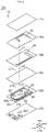
- Fig. 1 is an exploded perspective view of an ozone generation device 10a according to the embodiment.
- Fig. 2 illustrates, in overlapped relation, a discharge electrode 18, an induction electrode 20, and a heater electrode 22 of the ozone generation device 10a illustrated in Fig. 1 .
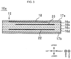
- Fig. 3 is a sectional view, taken along a line A-A in Fig. 1 , illustrating the structure of the ozone generation device 10a illustrated in Fig. 1 .
- a stacking direction of layers constituting the ozone generation device 10a is defined as an up and down direction.
- a direction in which a long side of the ozone generation device 10a extends when looked at in a plan view from above is defined as a front and rear direction.
- a direction in which a short side of the ozone generation device 10a extends when looked at in a plan view from above is defined as a left and right direction.
- the ozone generation device 10a includes a body 12, a discharge electrode 18, an induction electrode 20, a heater electrode 22, connection conductors 24 and 26, outer electrodes 30a to 30c, and via hole conductors v1 to v4, v11 to v13, and v21.
- the body 12 is a multilayer body made of a LTCC (low temperature co-fired ceramic) and having a substantially rectangular plate-like shape.
- the body 12 is constituted by stacking a protective layer 17a, dielectric layers 16a to 16d, and a protective layer 17b in the mentioned order from the upper side toward the lower side.
- Each of the dielectric layers 16a to 16d has a substantially rectangular shape and is made of a glass ceramic that is a mixture of glass (CaO-Al 2 O 3 -B 2 O 3 -SiO 2 ) powder and alumina (Al 2 O 3 ) filler.
- Each of the protective layers 17a and 17b has a substantially rectangular shape and is made of a glass ceramic as with the dielectric layers 16a to 16d.
- respective surfaces of the body 12, the dielectric layers 16a to 16d, and the protective layers 17a and 17b on the upper side are called upper surfaces
- respective surfaces of the body 12, the dielectric layers 16a to 16d, and the protective layers 17a and 17b on the lower side are called lower surfaces.
- the discharge electrode 18 is an electrode in the form of a line, which is made of Ag and which is disposed on the upper surface of the dielectric layer 16a.
- Cu, Pd or RuO 2 may also be used instead of Ag.
- the discharge electrode 18 extends from a point near a center (intersection point of diagonal lines) of the dielectric layer 16a to the vicinity of a left long side thereof, then extends along the left long side to the vicinity of a rear short side, and further extends toward the right side.
- an end portion of the discharge electrode 18, which is positioned near the center of the dielectric layer 16a, is called one end, and an end portion of the discharge electrode 18, which is positioned near a rear right corner of the dielectric layer 16a, is called the other end.
- the induction electrode 20 is an electrode in the form of a line, which is made of Ag and which is disposed on the upper surface of the dielectric layer 16b.
- Cu, Pd or RuO 2 may also be used instead of Ag.
- the induction electrode 20 extends from a front right corner of the dielectric layer 16b to the vicinity of a rear short side along a right long side thereof, and further extends toward the left side.
- an end portion of the induction electrode 20, which is positioned near the front right corner of the dielectric layer 16b is called one end
- an end portion of the induction electrode 20, which is positioned near a rear left corner of the dielectric layer 16b is called the other end.
- the heater electrode 22 is an electrode in the form of a line, which is made of, e.g., Nichrome or RuO 2 and which is disposed on the upper surface of the dielectric layer 16d different from the dielectric layers 16a and 16b including respectively the discharge electrode 18 and the induction electrode 20 disposed thereon.
- the material of the heater electrode 22 has a greater electrical resistivity than the materials of the discharge electrode 18 and the induction electrode 20. Ag, Cu or Pd, for example, may also be used instead of Nichrome or RuO 2 .
- the heater electrode 22 extends along a rear short side of the dielectric layer 16d. Thus, as illustrated in Fig.
- the heater electrode 22 is positioned to face the portion of the induction electrode 20, which extends from the right long side of the dielectric layer 16b toward the left side (i.e., to the other end of the induction electrode 20) with the dielectric layers 16b and 16c interposed therebetween.
- the heater electrode 22 are overlapped with one another when looked at in a plan view from above.
- a left end portion of the heater electrode 22 is called one end
- a right end portion of the heater electrode 22 is called the other end.
- the shortest distance between the discharge electrode 18 and the heater electrode 22 is longer than that between the discharge electrode 18 and the induction electrode 20.
- the induction electrode 20 is disposed nearer to the discharge electrode 18 than the heater electrode 22.
- the induction electrode 20 and the heater electrode 22 are disposed on one side (i.e., the lower side) in the stacking direction relative to the discharge electrode 18.
- connection conductor 24 is an electrode in the form of a line, which is made of Ag and which is disposed on the upper surface of the dielectric layer 16d.
- the connection conductor 24 is connected to the one end of the heater electrode 22.
- Cu, Pd or RuO 2 for example, may also be used instead of Ag.
- the connection conductor 24 extends from the one end of the heater electrode 22 to the vicinity of a front short side of the dielectric layer 16d along the left long side thereof, and further extends toward the right side along the front short side of the dielectric layer 16d.
- connection conductor 26 is an electrode in the form of a line, which is made of Ag and which is disposed on the upper surface of the dielectric layer 16d.
- the connection conductor 26 is connected to the other end of the heater electrode 22.
- Cu, Pd or RuO 2 may also be used instead of Ag.
- the connection conductor 26 extends from the other end of the heater electrode 22 to the vicinity of the front short side of the dielectric layer 16d along the right long side thereof.
- the outer electrode 30a is disposed near a center of the lower surface of the dielectric layer 16d.
- the outer electrodes 30b and 30c are disposed near a front short side of the lower surface of the dielectric layer 16d.
- the outer electrode 30c is disposed on the right side of the outer electrode 30b.
- the outer electrodes 30a to 30c are each formed, for example, by coating a resistance paste made of RuO 2 on an underlying electrode made of Ag for the purpose of preventing corrosion. Ni-plating and Sn-plating, for example, may be applied instead of coating the resistance paste made of RuO 2 . However, coating the resistance paste is more preferable because the plating accompanies with a risk that an amount of generated ozone may reduce due to corrosion.
- Openings Op1 to Op3 are formed in the protective layer 17b.
- the openings Op1 to Op3 are in overlapped relation to the outer electrodes 30a to 30c, respectively. Therefore, the outer electrodes 30a to 30c are exposed to the outside through the openings Op1 to Op3, respectively.
- the via hole conductors v1 to v4 penetrate through the dielectric layers 16a to 16d in the up and down direction, respectively.
- the via hole conductors v1 to v4 are interconnected to constitute one via hole conductor, thereby connecting the one end of the discharge electrode 18 and the outer electrode 30a to each other.
- the via hole conductors v11 to v13 penetrate through the dielectric layers 16b to 16d in the up and down direction, respectively.
- the via hole conductors v11 to v13 are interconnected to constitute one via hole conductor, thereby connecting the one end of the induction electrode 20 and the outer electrode 30c to each other.
- the via hole conductor v13 interconnects the connection conductor 26 and the outer electrode 30c. As a result, the other end of the heater electrode 22 and the outer electrode 30c are electrically connected to each other.
- the via hole conductor v21 penetrates through the dielectric layer 16d in the up and down direction, thereby interconnecting the connection conductor 24 and the outer electrode 30b. As a result, the one end of the heater electrode 22 and the outer electrode 30b are electrically connected to each other.
- the via hole conductors v1 to v4, v11 to v13, and v21 are constituted by filling a conductive paste, which contains, e.g., Ag as a main component, in through-holes formed in the dielectric layers 16a to 16d. Cu, Pd or RuO 2 , for example, may also be used instead of Ag.
- the ozone generation device 10a constituted as described above, only the one end of the discharge electrode 18 is electrically connected to the outer electrode 30a. Similarly, only the one end of the induction electrode 20 is electrically connected to the outer electrode 30c. On the other hand, both the ends of the heater electrode 22 are electrically connected to the outer electrodes 30b and 30c, respectively.
- the outer electrode 30a electrically connected to the one end of the discharge electrode 18 corresponds to a "first outer electrode” in Claims.
- the outer electrode 30c electrically connected to the one end of the induction electrode 20 and to the other end (corresponding to a "first end portion” in Claims) of the heater electrode 22 corresponds to a "second outer electrode” in Claims.
- the outer electrode 30b electrically connected to the one end (corresponding to a "second end portion” in Claims) of the heater electrode 22 corresponds to a "third outer electrode” in Claims.
- a high AC voltage is applied to the outer electrode 30a, and the outer electrode 30c is held at a ground potential.
- the high AC voltage is, for example, an AC voltage having a frequency of about 20 kHz to 50 kHz and a peak-to-peak voltage of about 4 kV to 7 kV. Furthermore, a relatively low DC voltage of about 12 V is applied to the outer electrode 30b.
- the heater electrode 22 because the DC voltage is applied to the heater electrode 22, the heater electrode 22 generates heat. Therefore, the temperature around the discharge electrode 18 rises, and the humidity around the discharge electrode 18 lowers. Accordingly, the occurrence of due drops is suppressed around the discharge electrode 18.
- a method of manufacturing the ozone generation device 10a will be described below with reference to Fig. 1 . It is to be noted that, while the manufacturing method for one ozone generation device 10a is described here, a plurality of multilayer bodies is manufactured at the same time in practice by stacking large-sized mother ceramic green sheets to fabricate a mother multilayer body, and by cutting the mother multilayer body into plural multilayer bodies per unit size.
- ceramic green sheets are fabricated which become the dielectric layers 16a to 16d and the protective layers 17a and 17b later. More specifically, glass ceramic slurry made of a mixture of glass powder and alumina filler is prepared. The prepared glass ceramic slurry is formed into a sheet-like shape on a carrier film of PET (polyethylene terephthalate) by the doctor blade method, and is then dried to fabricate the ceramic green sheets that become the dielectric layers 16a to 16d and the protective layers 17a and 17b later.
- PET polyethylene terephthalate
- the via hole conductors v1 to v4, v11 to v13, and v21 are formed in the ceramic green sheets becoming the dielectric layers 16a to 16d later. More specifically, via holes are formed in the ceramic green sheets, which become the dielectric layers 16a to 16d later, by irradiating the ceramic green sheets with a laser beam. A paste containing a conductor material, e.g., Ag, is filled into the via holes by printing or any other suitable method, thus forming the via hole conductors v1 to v4, v11 to v13, and v21.
- a conductor material e.g., Ag
- the opening Op1 to Op3 are formed in the ceramic green sheets, which become the protective layer 17b later, by punching with a punch, for example.
- the discharge electrode 18, the induction electrode 20, and the connection conductors 24 and 26 are formed, as illustrated in Fig. 1 , by applying a paste, made of a conductive material containing, e.g., Ag, to upper surfaces of the ceramic green sheets by screen printing, which become the dielectric layers 16a, 16b, and 16d later.
- the paste made of the conductive material is prepared, for example, by adding varnish and a solvent to e.g. Ag powder.
- the heater electrode 22 is formed, as illustrated in Fig. 1 , by applying a paste, made of a conductive material containing, e.g., RuO 2 , to the upper surface of the ceramic green sheet with screen printing, which becomes the dielectric layer 16d later.
- the paste made of the conductive material is prepared, for example, by adding varnish and a solvent to metal powder, e.g., RuO 2 powder.
- Ag electrodes serving as respective underlying electrodes for the outer electrodes 30a to 30c are formed, as illustrated in Fig. 1 , by applying a paste, made of a conductive material containing, e.g., Ag, to a lower surface of the ceramic green sheet with screen printing, which becomes the dielectric layer 16d later.
- the paste made of the conductive material is prepared, for example, by adding varnish and a solvent to metal powder, e.g., Ag powder.
- a mother multilayer body in an unfired state is formed by stacking and tentatively pressure-bonding the ceramic green sheets, which become the protective layer 17a, the dielectric layers 16a to 16d, and the protective layer 17b later one by one such that those layers are arranged in the mentioned order from the upper side toward the lower side in the up and down direction.
- main pressure bonding is performed on the mother multilayer body by thermal compression bonding.
- the mother multilayer body is cut into individual unfired bodies 12.
- the unfired bodies 12 are each subject to a binder removing process and a firing process.
- the dielectric layers 16a to 16d and the protective layers 17a and 17b are fired at the same time.
- the outer electrodes 30a to 30c are formed by applying a high resistance paste made of RuO 2 to surfaces of the Ag electrodes that become the outer electrodes 30a to 30c later and firing.
- the ozone generation device 10a is completed through the above-described steps.
- a degree of freedom in layout of the heater electrode 22 can be increased as described below.
- the heater electrode 22 is disposed on the dielectric layer 16d different from the dielectric layer 16a on which the discharge electrode 18 is disposed, and from the dielectric layer 16b on which the induction electrode 20 is disposed. Therefore, even when the heater electrode 22, the discharge electrode 18, and the induction electrode 20 are arranged close to each other when looked at in a plan view from above, short-circuiting is hard to occur between those electrodes. As a result, the degree of freedom in layout of the heater electrode 22 can be increased in the ozone generation device 10a.
- the heater electrode 22, the discharge electrode 18, and the induction electrode 20 can be arranged close to each other in the ozone generation device 10a, the size of the ozone generation device 10a can be reduced.
- discharge can be more stably generated.
- a leak current tends to more easily generate between the discharge electrode 18 and the induction electrode 20. This gives rise to a situation that discharge is less apt to generate between the discharge electrode 18 and the induction electrode 20.
- the heater electrode 22 is disposed in the ozone generation device 10a.
- the heater electrode 22 functions to lower the humidity in the surroundings of the discharge electrode 18 and the induction electrode 20, and to suppress the generation of the leak current between the discharge electrode 18 and the induction electrode 20.
- the heater electrode 22 is disposed, as described above, on the dielectric layer 16d different from the dielectric layer 16a on which the discharge electrode 18 is disposed, and from the dielectric layer 16b on which the induction electrode 20 is disposed. Therefore, the heater electrode 22 can be arranged in overlapped relation to the discharge electrode 18 when looked at in a plan view from above. Such an arrangement can more effectively lower the humidity in the surroundings of the discharge electrode 18. As a result, the ozone generation device 10a can more stably generate discharge.
- the shortest distance between the discharge electrode 18 and the heater electrode 22 is longer than that between the discharge electrode 18 and the induction electrode 20. Such an arrangement ensures that discharge is generated between the discharge electrode 18 and the induction electrode 20, and that the generation of discharge between the discharge electrode 18 and the heater electrode 22 is suppressed.
- the discharge electrode 18, the induction electrode 20, and the heater electrode 22 are disposed on the upper surfaces of the different dielectric layers 16a, 16b, and 16d, respectively. Therefore, short-circuiting is hard to occur between two of the discharge electrode 18, the induction electrode 20, and the heater electrode 22.
- the discharge electrode 18, the induction electrode 20, and the heater electrode 22 are disposed inside the body 12 and are not exposed to the outside. Therefore, any of the discharge electrode 18, the induction electrode 20, and the heater electrode 22 is suppressed from contacting a conductor that is present around the ozone generation device 10a.
- the ozone generation device 10a After forming the discharge electrode 18, the induction electrode 20, the heater electrode 22, and the connection conductors 24 and 26 on the dielectric layers 16a, 16b, and 16d, the dielectric layers 16a to 16d and the protective layers 17a and 17b are stacked into the body 12, and the body 12 is then fired. In other words, when the body 12 is fired, the discharge electrode 18, the induction electrode 20, the heater electrode 22, and the connection conductors 24 and 26 are also fired together. Therefore, the firing of the discharge electrode 18, the induction electrode 20, the heater electrode 22, and the connection conductors 24 and 26 can be performed at the same time as the firing of the body 12. As a result, the number of manufacturing steps of the ozone generation device 10a can be reduced.
- FIG. 4 is an exploded perspective view of the ozone generation device 10b according to the first modification.
- Fig. 5 illustrates, in overlapped relation, a discharge electrode 18, an induction electrode 20, and a heater electrode 32 of the ozone generation device 10b illustrated in Fig. 4 .
- the ozone generation device 10b is different from the ozone generation device 10a in that the heater electrode 32 is disposed instead of the heater electrode 22.
- the following description of the ozone generation device 10b is made primarily about such a different point.
- the heater electrode 32 is disposed on the upper surface of the dielectric layer 16d.
- the heater electrode 32 extends along the right long side of the dielectric layer 16d.
- the heater electrode 32 is disposed on the left side of a portion of the induction electrode 20, which extends along the right long side of the dielectric layer 16b, when looked at in a plan view from above.
- the heater electrode 32 is disposed between the one end of the discharge electrode 18 and the portion of the induction electrode 20, which extends along the right long side of the dielectric layer 16b, when looked at in a plan view from above.
- the heater electrode 32 is electrically connected to the outer electrodes 30b and 30c through the connection conductors 24 and 26.
- the ozone generation device 10b constituted as described above, discharge can be stably generated. More specifically, in the arrangement that the one end of the discharge electrode 18 and the portion of the induction electrode 20, which extends along the right long side of the dielectric layer 16b, are positioned close to each other, there is a possibility that a leak current may generate therebetween.
- the heater electrode 32 is disposed between the one end of the discharge electrode 18 and the portion of the induction electrode 20, which extends along the right long side of the dielectric layer 16b, when looked at in a plan view from above. The presence of the heater electrode 32 at such a position is effective in suppressing the generation of a leak current therebetween. As a result, the ozone generation device 10b can stably generate discharge.
- FIG. 6 is an exploded perspective view of the ozone generation device 10c according to the second modification.
- Fig. 7 illustrates, in overlapped relation, a discharge electrode 18, an induction electrode 20, and heater electrodes 22 and 32 of the ozone generation device 10c illustrated in Fig. 6 .
- the ozone generation device 10c is different from the ozone generation device 10b in further including the heater electrode 22.
- the following description of the ozone generation device 10c is made primarily about such a different point.
- the heater electrode 22 of the ozone generation device 10c has the same configuration as the heater electrode 22 of the ozone generation device 10a. Furthermore, the heater electrode 32 of the ozone generation device 10c has the same configuration as the heater electrode 32 of the ozone generation device 10b. The heater electrodes 22 and 32 are electrically connected to the outer electrodes 30b and 30c through the connection conductors 24 and 26.
- discharge can be stably generated as with the ozone generation devices 10a and 10b.
- FIG. 8 is an exploded perspective view of the ozone generation device 10d according to the third modification.
- Fig. 9 illustrates, in overlapped relation, a discharge electrode 18, an induction electrode 20, and heater electrodes 22 and 42 of the ozone generation device 10d illustrated in Fig. 8 .
- the ozone generation device 10d is different from the ozone generation device 10c in that the heater electrode 42 is disposed instead of the heater electrode 32.
- the following description of the ozone generation device 10d is made primarily about such a different point.
- the heater electrode 42 is disposed on the upper surface of the dielectric layer 16d.
- the heater electrode 42 extends in the left and right direction between the outer electrode 30a and the outer electrodes 30b and 30c when looked at in a plan view from above. Furthermore, the heater electrode 42 is electrically connected to the outer electrodes 30b and 30c through the connection conductors 24 and 26.
- the ozone generation device 10d constituted as described above, discharge can be stably generated.
- the AC high voltage is applied to the outer electrode 30a and the DC voltage is applied to the outer electrode 30b, whereas the outer electrode 30c is held at the ground potential. Therefore, a large potential difference occurs between the outer electrode 30a and the outer electrodes 30b and 30c. Hence there is a possibility that, when humidity increases in a region between the outer electrode 30a and the outer electrodes 30b and 30c, a leak current may generate therebetween.
- the heater electrode 42 is disposed between the outer electrode 30a and the outer electrodes 30b and 30c when looked at in a plan view from above. With such an arrangement, a rise of the humidity in the region between the outer electrode 30a and the outer electrodes 30b and 30c is suppressed, and the occurrence of a leak current therebetween is also suppressed. Thus, the ozone generation device 10d can stably generate discharge.
- the heater electrode 42 may be disposed between the outer electrode 30a and the outer electrode 30b, or between the outer electrode 30a and the outer electrode 30c.
- the discharge device according to the present invention is not limited to the examples described above as the ozone generation devices 10a to 10d, and it can be modified within the scope not departing from the gist of the present invention.
- each of the ozone generation devices 10a to 10d can be applied to an ion generation device as well, which ionizes air molecules through discharge.
- the ozone generation devices 10a to 10d are applied to a water supply apparatus, a refrigerator, and so on.
- the water supply apparatus can be given with the humidifying function of vaporizing water in the water supply apparatus by heat generated from the heater electrode 22.
- the ozone generation devices 10a to 10d are each made of the glass ceramic, there is no possibility of contact of water with not only lead and other metals, but also organic substances. Accordingly, a water supply apparatus being superior from the viewpoint of hygiene can be obtained.
- the refrigerator can also be given with the humidifying function.
- the present invention is usefully applied to a discharge device.
- the present invention is superior in that a degree of freedom in layout of the heater electrode is high.
Landscapes
- Chemical & Material Sciences (AREA)
- Organic Chemistry (AREA)
- Inorganic Chemistry (AREA)
- Health & Medical Sciences (AREA)
- General Health & Medical Sciences (AREA)
- Toxicology (AREA)
- Oxygen, Ozone, And Oxides In General (AREA)
Claims (7)
- Eine Entladungsvorrichtung, die folgende Merkmale aufweist:einen Körper (12), der aus einer Mehrzahl von übereinander gestapelten Dielektrikumschichten (16a-16d) zusammengesetzt ist;eine Entladungselektrode (18), die in dem Körper (12) angeordnet ist;eine Induktionselektrode (20), die in dem Körper (12) angeordnet ist, um der Entladungselektrode (18) zugewandt zu sein, wobei zumindest eine der Dielektrikumschichten (16a) zwischen denselben angeordnet ist; undeine Heizelektrode (22, 32, 42), die auf einer Dielektrikumschicht (16d) angeordnet ist, die von einer Dielektrikumschicht (16a), auf der die Entladungselektrode (18) angeordnet ist, und von einer Dielektrikumschicht (16b), auf der die Induktionselektrode (20) angeordnet ist, verschieden ist;eine erste Außenelektrode (30a), die mit der Entladungselektrode (18) elektrisch verbunden ist;eine zweite Außenelektrode (30c), die mit der Induktionselektrode (20) und mit einem erstem Endabschnitt der Heizelektrode (22, 32, 42) elektrisch verbunden ist; undeine dritte Außenelektrode (30b), die mit einem zweiten Endabschnitt der Heizelektrode (22, 32, 42) elektrisch verbunden ist.
- Die Entladungsvorrichtung gemäß Anspruch 1, bei der jede der Dielektrikumschich - ten (16a-16d) eine rechteckige Form aufweist und die Mehrzahl von Dielektrikumschichten so gestapelt ist, dass erste und zweite kurze Seiten und erste und zweite lange Seiten derselben miteinander ausgerichtet sind, wobei die Entladungselektrode (18) sich von einem Punkt nahe der Mitte, das heißt dem Schnittpunkt von diagonalen Linien, einer Dielektrikumschicht (16a), auf der dieselbe angeordnet ist, bis in die Nähe einer langen Seite derselben erstreckt, sich dann entlang der ersten langen Seite bis in die Nähe der ersten kurzen Seite derselben erstreckt und sich weiter zu der zweiten langen Seite derselben erstreckt, wobei die Induktionselektrode (20) sich von einer ersten Ecke einer Dielektrikumschicht (16b), auf der dieselbe angeordnet ist, bis in die Nähe der ersten kurzen Seite entlang der zweiten langen Seite derselben erstreckt und sich weiter zu der ersten langen Seite derselben erstreckt, und wobei ein Abschnitt der Entladungselektrode (18), der sich von der ersten langen Seite der Dielektrikumschicht zu der zweiten langen Seite erstreckt, positioniert ist, um einem Abschnitt der Induktionselektrode (20), der sich von der zweiten langen Seite der Dielektrikumschicht zu der ersten langen Seite derselben erstreckt, zugewandt zu sein.
- Die Entladungsvorrichtung gemäß Anspruch 1 oder 2, bei der ein kürzester Abstand zwischen der Entladungselektrode (18) und der Heizelektrode (22, 32, 42) länger als ein kürzester Abstand zwischen der Entladungselektrode (18) und der Induktionselektrode (20) ist.
- Die Entladungsvorrichtung gemäß Anspruch 3, bei der die Heizelektrode (22, 32, 42) und die Induktionselektrode (20) in einer Stapelrichtung der mehreren Dielektrikumschichten (16a-16d) relativ zu der Entladungselektrode (18) auf einer Seite angeordnet sind.
- Die Entladungsvorrichtung gemäß einem der Ansprüche 1 bis 4, bei der die Heizelektrode (22, 32, 42) bei Betrachtung in Draufsicht von einer Stapelrichtung der mehreren Dielektrikumschichten (16a-16d) aus mit der Entladungselektrode (18) überlappt.
- Die Entladungsvorrichtung gemäß einem der Ansprüche 1 bis 4, bei der die Heizelektrode (32) bei Betrachtung in Draufsicht von einer Stapelrichtung der mehreren Dielektrikumschichten (16a-16d) aus zwischen der Entladungselektrode (18) und der Induktionselektrode (20) angeordnet ist.
- Die Entladungsvorrichtung gemäß einem der Ansprüche 1 bis 4, bei der die Heizelektrode (42) bei Betrachtung in Draufsicht von einer Stapelrichtung der mehreren Dielektrikumschichten (16a-16d) aus zwischen der ersten Außenelektrode (30a) und zumindest der zweiten Außenelektrode (30c) und/oder der dritten Außenelektrode (30b) angeordnet ist.
Applications Claiming Priority (1)
| Application Number | Priority Date | Filing Date | Title |
|---|---|---|---|
| JP2013103971A JP5983529B2 (ja) | 2013-05-16 | 2013-05-16 | 放電素子 |
Publications (2)
| Publication Number | Publication Date |
|---|---|
| EP2803637A1 EP2803637A1 (de) | 2014-11-19 |
| EP2803637B1 true EP2803637B1 (de) | 2018-03-28 |
Family
ID=50771041
Family Applications (1)
| Application Number | Title | Priority Date | Filing Date |
|---|---|---|---|
| EP14167576.9A Active EP2803637B1 (de) | 2013-05-16 | 2014-05-08 | Entladevorrichtung |
Country Status (4)
| Country | Link |
|---|---|
| US (1) | US9414475B2 (de) |
| EP (1) | EP2803637B1 (de) |
| JP (1) | JP5983529B2 (de) |
| CN (1) | CN104163401B (de) |
Families Citing this family (4)
| Publication number | Priority date | Publication date | Assignee | Title |
|---|---|---|---|---|
| JP6350680B2 (ja) * | 2015-01-30 | 2018-07-04 | 株式会社村田製作所 | オゾン生成装置 |
| CN107207250B (zh) * | 2015-02-13 | 2019-04-26 | 株式会社村田制作所 | 臭氧生成装置 |
| WO2016190139A1 (ja) * | 2015-05-27 | 2016-12-01 | 株式会社クリエイティブテクノロジー | 除菌シート |
| JP6504317B2 (ja) * | 2016-07-14 | 2019-04-24 | 株式会社村田製作所 | オゾン発生装置 |
Family Cites Families (16)
| Publication number | Priority date | Publication date | Assignee | Title |
|---|---|---|---|---|
| JPS5944797A (ja) * | 1982-09-07 | 1984-03-13 | 増田 閃一 | 物体の静電的処理装置 |
| JPS601437U (ja) * | 1983-06-17 | 1985-01-08 | 日本特殊陶業株式会社 | 電界装置 |
| JPH05166578A (ja) * | 1991-12-12 | 1993-07-02 | Ngk Spark Plug Co Ltd | 沿面コロナ放電素子及びその放電面生成物の除去方法 |
| JP3951064B2 (ja) | 1992-11-05 | 2007-08-01 | 増田 佳子 | 脱臭装置 |
| JPH0927380A (ja) * | 1995-07-12 | 1997-01-28 | Aiwa Co Ltd | オゾン発生装置 |
| US6024930A (en) * | 1996-08-08 | 2000-02-15 | Quantum Electronics Corporation | Ozone generator plate |
| US6039816A (en) * | 1997-06-12 | 2000-03-21 | Ngk Spark Plug Co., Ltd. | Ozonizer, water purifier and method of cleaning an ozonizer |
| JPH11139810A (ja) * | 1997-11-04 | 1999-05-25 | Ngk Spark Plug Co Ltd | オゾン発生装置、水浄化装置およびこれらのクリーニング方法 |
| JPH11139807A (ja) | 1997-11-07 | 1999-05-25 | Nippon Cement Co Ltd | セラミック放電基板 |
| JP2003036954A (ja) * | 2001-05-15 | 2003-02-07 | Ngk Spark Plug Co Ltd | イオン発生素子及びイオン発生装置 |
| JP2003123939A (ja) * | 2001-10-12 | 2003-04-25 | Sharp Corp | イオン発生装置及び空気調節装置 |
| JP2006162195A (ja) | 2004-12-09 | 2006-06-22 | Toshiba Corp | 冷蔵庫 |
| JP4536087B2 (ja) * | 2007-06-29 | 2010-09-01 | シャープ株式会社 | イオン発生素子、帯電装置および画像形成装置 |
| JP2009300597A (ja) * | 2008-06-11 | 2009-12-24 | Sharp Corp | イオン発生素子、帯電装置および画像形成装置 |
| JP2010145970A (ja) * | 2008-12-22 | 2010-07-01 | Sharp Corp | イオン発生素子、帯電装置および画像形成装置 |
| JP2013166660A (ja) | 2012-02-14 | 2013-08-29 | Murata Mfg Co Ltd | オゾン発生素子及びその製造方法 |
-
2013
- 2013-05-16 JP JP2013103971A patent/JP5983529B2/ja active Active
-
2014
- 2014-05-08 EP EP14167576.9A patent/EP2803637B1/de active Active
- 2014-05-12 US US14/274,807 patent/US9414475B2/en active Active
- 2014-05-13 CN CN201410200497.1A patent/CN104163401B/zh active Active
Non-Patent Citations (1)
| Title |
|---|
| None * |
Also Published As
| Publication number | Publication date |
|---|---|
| US20140340810A1 (en) | 2014-11-20 |
| CN104163401B (zh) | 2017-04-12 |
| JP5983529B2 (ja) | 2016-08-31 |
| CN104163401A (zh) | 2014-11-26 |
| EP2803637A1 (de) | 2014-11-19 |
| JP2014224013A (ja) | 2014-12-04 |
| US9414475B2 (en) | 2016-08-09 |
Similar Documents
| Publication | Publication Date | Title |
|---|---|---|
| JP6937176B2 (ja) | 電子部品、電子装置、及び電子部品の製造方法 | |
| EP2803637B1 (de) | Entladevorrichtung | |
| KR20130039400A (ko) | 적층 세라믹 전자 부품 및 그 제조 방법 | |
| WO2014188792A1 (ja) | Esd保護装置 | |
| US7535694B2 (en) | Feedthrough multilayer capacitor | |
| EP3840020A3 (de) | Komponententräger mit doppelter dielektrischer schicht und verfahren zu seiner herstellung | |
| JP2016157904A (ja) | 積層コンデンサ | |
| KR102161768B1 (ko) | 대전력 커패시터 | |
| US9044728B2 (en) | Ozone generating element and method for manufacturing ozone generating element | |
| JP2016152300A (ja) | コンデンサモジュール | |
| US9780533B2 (en) | ESD protective device | |
| JP2010098052A (ja) | 積層貫通コンデンサ | |
| JP2016012728A (ja) | 積層電子部品 | |
| JP6079880B2 (ja) | Esd保護装置 | |
| CN107112726B (zh) | 静电放电保护构造体以及其制造方法 | |
| JP2012204475A (ja) | 積層電子部品 | |
| JP4983462B2 (ja) | オゾン発生素子及びその製造方法 | |
| JP2017120877A (ja) | 積層電子部品及びその製造方法 | |
| WO2014188791A1 (ja) | Esd保護装置 | |
| JP7489519B2 (ja) | ガラス誘電体コンデンサ及びガラス誘電体コンデンサの製造プロセス | |
| JP6252020B2 (ja) | 静電気保護部品及び静電気保護部品の製造方法 | |
| JP2017212431A (ja) | キャパシタ及びこれを含む回路基板 | |
| WO2014080411A1 (en) | A wound film capacitor with improved heat evacuation | |
| JP2009038333A (ja) | 貫通型積層コンデンサ | |
| WO2021122722A1 (de) | Hochfrequenz-hochspannungs-stromleiter-vorrichtung |
Legal Events
| Date | Code | Title | Description |
|---|---|---|---|
| PUAI | Public reference made under article 153(3) epc to a published international application that has entered the european phase |
Free format text: ORIGINAL CODE: 0009012 |
|
| 17P | Request for examination filed |
Effective date: 20140508 |
|
| AK | Designated contracting states |
Kind code of ref document: A1 Designated state(s): AL AT BE BG CH CY CZ DE DK EE ES FI FR GB GR HR HU IE IS IT LI LT LU LV MC MK MT NL NO PL PT RO RS SE SI SK SM TR |
|
| AX | Request for extension of the european patent |
Extension state: BA ME |
|
| R17P | Request for examination filed (corrected) |
Effective date: 20150519 |
|
| RBV | Designated contracting states (corrected) |
Designated state(s): AL AT BE BG CH CY CZ DE DK EE ES FI FR GB GR HR HU IE IS IT LI LT LU LV MC MK MT NL NO PL PT RO RS SE SI SK SM TR |
|
| GRAP | Despatch of communication of intention to grant a patent |
Free format text: ORIGINAL CODE: EPIDOSNIGR1 |
|
| INTG | Intention to grant announced |
Effective date: 20171005 |
|
| GRAS | Grant fee paid |
Free format text: ORIGINAL CODE: EPIDOSNIGR3 |
|
| GRAA | (expected) grant |
Free format text: ORIGINAL CODE: 0009210 |
|
| AK | Designated contracting states |
Kind code of ref document: B1 Designated state(s): AL AT BE BG CH CY CZ DE DK EE ES FI FR GB GR HR HU IE IS IT LI LT LU LV MC MK MT NL NO PL PT RO RS SE SI SK SM TR |
|
| REG | Reference to a national code |
Ref country code: GB Ref legal event code: FG4D |
|
| REG | Reference to a national code |
Ref country code: CH Ref legal event code: EP |
|
| REG | Reference to a national code |
Ref country code: AT Ref legal event code: REF Ref document number: 983239 Country of ref document: AT Kind code of ref document: T Effective date: 20180415 |
|
| REG | Reference to a national code |
Ref country code: IE Ref legal event code: FG4D |
|
| REG | Reference to a national code |
Ref country code: DE Ref legal event code: R096 Ref document number: 602014022889 Country of ref document: DE |
|
| PG25 | Lapsed in a contracting state [announced via postgrant information from national office to epo] |
Ref country code: NO Free format text: LAPSE BECAUSE OF FAILURE TO SUBMIT A TRANSLATION OF THE DESCRIPTION OR TO PAY THE FEE WITHIN THE PRESCRIBED TIME-LIMIT Effective date: 20180628 Ref country code: FI Free format text: LAPSE BECAUSE OF FAILURE TO SUBMIT A TRANSLATION OF THE DESCRIPTION OR TO PAY THE FEE WITHIN THE PRESCRIBED TIME-LIMIT Effective date: 20180328 Ref country code: HR Free format text: LAPSE BECAUSE OF FAILURE TO SUBMIT A TRANSLATION OF THE DESCRIPTION OR TO PAY THE FEE WITHIN THE PRESCRIBED TIME-LIMIT Effective date: 20180328 Ref country code: LT Free format text: LAPSE BECAUSE OF FAILURE TO SUBMIT A TRANSLATION OF THE DESCRIPTION OR TO PAY THE FEE WITHIN THE PRESCRIBED TIME-LIMIT Effective date: 20180328 |
|
| REG | Reference to a national code |
Ref country code: NL Ref legal event code: MP Effective date: 20180328 |
|
| REG | Reference to a national code |
Ref country code: LT Ref legal event code: MG4D |
|
| PG25 | Lapsed in a contracting state [announced via postgrant information from national office to epo] |
Ref country code: BG Free format text: LAPSE BECAUSE OF FAILURE TO SUBMIT A TRANSLATION OF THE DESCRIPTION OR TO PAY THE FEE WITHIN THE PRESCRIBED TIME-LIMIT Effective date: 20180628 Ref country code: GR Free format text: LAPSE BECAUSE OF FAILURE TO SUBMIT A TRANSLATION OF THE DESCRIPTION OR TO PAY THE FEE WITHIN THE PRESCRIBED TIME-LIMIT Effective date: 20180629 Ref country code: SE Free format text: LAPSE BECAUSE OF FAILURE TO SUBMIT A TRANSLATION OF THE DESCRIPTION OR TO PAY THE FEE WITHIN THE PRESCRIBED TIME-LIMIT Effective date: 20180328 Ref country code: LV Free format text: LAPSE BECAUSE OF FAILURE TO SUBMIT A TRANSLATION OF THE DESCRIPTION OR TO PAY THE FEE WITHIN THE PRESCRIBED TIME-LIMIT Effective date: 20180328 Ref country code: RS Free format text: LAPSE BECAUSE OF FAILURE TO SUBMIT A TRANSLATION OF THE DESCRIPTION OR TO PAY THE FEE WITHIN THE PRESCRIBED TIME-LIMIT Effective date: 20180328 |
|
| PG25 | Lapsed in a contracting state [announced via postgrant information from national office to epo] |
Ref country code: EE Free format text: LAPSE BECAUSE OF FAILURE TO SUBMIT A TRANSLATION OF THE DESCRIPTION OR TO PAY THE FEE WITHIN THE PRESCRIBED TIME-LIMIT Effective date: 20180328 Ref country code: NL Free format text: LAPSE BECAUSE OF FAILURE TO SUBMIT A TRANSLATION OF THE DESCRIPTION OR TO PAY THE FEE WITHIN THE PRESCRIBED TIME-LIMIT Effective date: 20180328 Ref country code: IT Free format text: LAPSE BECAUSE OF FAILURE TO SUBMIT A TRANSLATION OF THE DESCRIPTION OR TO PAY THE FEE WITHIN THE PRESCRIBED TIME-LIMIT Effective date: 20180328 Ref country code: ES Free format text: LAPSE BECAUSE OF FAILURE TO SUBMIT A TRANSLATION OF THE DESCRIPTION OR TO PAY THE FEE WITHIN THE PRESCRIBED TIME-LIMIT Effective date: 20180328 Ref country code: AL Free format text: LAPSE BECAUSE OF FAILURE TO SUBMIT A TRANSLATION OF THE DESCRIPTION OR TO PAY THE FEE WITHIN THE PRESCRIBED TIME-LIMIT Effective date: 20180328 Ref country code: RO Free format text: LAPSE BECAUSE OF FAILURE TO SUBMIT A TRANSLATION OF THE DESCRIPTION OR TO PAY THE FEE WITHIN THE PRESCRIBED TIME-LIMIT Effective date: 20180328 Ref country code: PL Free format text: LAPSE BECAUSE OF FAILURE TO SUBMIT A TRANSLATION OF THE DESCRIPTION OR TO PAY THE FEE WITHIN THE PRESCRIBED TIME-LIMIT Effective date: 20180328 |
|
| PG25 | Lapsed in a contracting state [announced via postgrant information from national office to epo] |
Ref country code: CZ Free format text: LAPSE BECAUSE OF FAILURE TO SUBMIT A TRANSLATION OF THE DESCRIPTION OR TO PAY THE FEE WITHIN THE PRESCRIBED TIME-LIMIT Effective date: 20180328 Ref country code: SK Free format text: LAPSE BECAUSE OF FAILURE TO SUBMIT A TRANSLATION OF THE DESCRIPTION OR TO PAY THE FEE WITHIN THE PRESCRIBED TIME-LIMIT Effective date: 20180328 Ref country code: SM Free format text: LAPSE BECAUSE OF FAILURE TO SUBMIT A TRANSLATION OF THE DESCRIPTION OR TO PAY THE FEE WITHIN THE PRESCRIBED TIME-LIMIT Effective date: 20180328 |
|
| REG | Reference to a national code |
Ref country code: CH Ref legal event code: PL |
|
| REG | Reference to a national code |
Ref country code: AT Ref legal event code: MK05 Ref document number: 983239 Country of ref document: AT Kind code of ref document: T Effective date: 20180328 |
|
| PG25 | Lapsed in a contracting state [announced via postgrant information from national office to epo] |
Ref country code: PT Free format text: LAPSE BECAUSE OF FAILURE TO SUBMIT A TRANSLATION OF THE DESCRIPTION OR TO PAY THE FEE WITHIN THE PRESCRIBED TIME-LIMIT Effective date: 20180730 |
|
| REG | Reference to a national code |
Ref country code: DE Ref legal event code: R097 Ref document number: 602014022889 Country of ref document: DE |
|
| REG | Reference to a national code |
Ref country code: BE Ref legal event code: MM Effective date: 20180531 |
|
| PG25 | Lapsed in a contracting state [announced via postgrant information from national office to epo] |
Ref country code: AT Free format text: LAPSE BECAUSE OF FAILURE TO SUBMIT A TRANSLATION OF THE DESCRIPTION OR TO PAY THE FEE WITHIN THE PRESCRIBED TIME-LIMIT Effective date: 20180328 Ref country code: DK Free format text: LAPSE BECAUSE OF FAILURE TO SUBMIT A TRANSLATION OF THE DESCRIPTION OR TO PAY THE FEE WITHIN THE PRESCRIBED TIME-LIMIT Effective date: 20180328 Ref country code: MC Free format text: LAPSE BECAUSE OF FAILURE TO SUBMIT A TRANSLATION OF THE DESCRIPTION OR TO PAY THE FEE WITHIN THE PRESCRIBED TIME-LIMIT Effective date: 20180328 |
|
| PLBE | No opposition filed within time limit |
Free format text: ORIGINAL CODE: 0009261 |
|
| STAA | Information on the status of an ep patent application or granted ep patent |
Free format text: STATUS: NO OPPOSITION FILED WITHIN TIME LIMIT |
|
| REG | Reference to a national code |
Ref country code: IE Ref legal event code: MM4A |
|
| GBPC | Gb: european patent ceased through non-payment of renewal fee |
Effective date: 20180628 |
|
| PG25 | Lapsed in a contracting state [announced via postgrant information from national office to epo] |
Ref country code: CH Free format text: LAPSE BECAUSE OF NON-PAYMENT OF DUE FEES Effective date: 20180531 Ref country code: LI Free format text: LAPSE BECAUSE OF NON-PAYMENT OF DUE FEES Effective date: 20180531 |
|
| 26N | No opposition filed |
Effective date: 20190103 |
|
| PG25 | Lapsed in a contracting state [announced via postgrant information from national office to epo] |
Ref country code: LU Free format text: LAPSE BECAUSE OF NON-PAYMENT OF DUE FEES Effective date: 20180508 |
|
| PG25 | Lapsed in a contracting state [announced via postgrant information from national office to epo] |
Ref country code: IE Free format text: LAPSE BECAUSE OF NON-PAYMENT OF DUE FEES Effective date: 20180508 Ref country code: FR Free format text: LAPSE BECAUSE OF NON-PAYMENT OF DUE FEES Effective date: 20180528 Ref country code: GB Free format text: LAPSE BECAUSE OF NON-PAYMENT OF DUE FEES Effective date: 20180628 |
|
| PG25 | Lapsed in a contracting state [announced via postgrant information from national office to epo] |
Ref country code: SI Free format text: LAPSE BECAUSE OF FAILURE TO SUBMIT A TRANSLATION OF THE DESCRIPTION OR TO PAY THE FEE WITHIN THE PRESCRIBED TIME-LIMIT Effective date: 20180328 Ref country code: BE Free format text: LAPSE BECAUSE OF NON-PAYMENT OF DUE FEES Effective date: 20180531 |
|
| PG25 | Lapsed in a contracting state [announced via postgrant information from national office to epo] |
Ref country code: MT Free format text: LAPSE BECAUSE OF NON-PAYMENT OF DUE FEES Effective date: 20180508 |
|
| PG25 | Lapsed in a contracting state [announced via postgrant information from national office to epo] |
Ref country code: TR Free format text: LAPSE BECAUSE OF FAILURE TO SUBMIT A TRANSLATION OF THE DESCRIPTION OR TO PAY THE FEE WITHIN THE PRESCRIBED TIME-LIMIT Effective date: 20180328 |
|
| PG25 | Lapsed in a contracting state [announced via postgrant information from national office to epo] |
Ref country code: HU Free format text: LAPSE BECAUSE OF FAILURE TO SUBMIT A TRANSLATION OF THE DESCRIPTION OR TO PAY THE FEE WITHIN THE PRESCRIBED TIME-LIMIT; INVALID AB INITIO Effective date: 20140508 |
|
| PG25 | Lapsed in a contracting state [announced via postgrant information from national office to epo] |
Ref country code: MK Free format text: LAPSE BECAUSE OF NON-PAYMENT OF DUE FEES Effective date: 20180328 Ref country code: CY Free format text: LAPSE BECAUSE OF FAILURE TO SUBMIT A TRANSLATION OF THE DESCRIPTION OR TO PAY THE FEE WITHIN THE PRESCRIBED TIME-LIMIT Effective date: 20180328 |
|
| PG25 | Lapsed in a contracting state [announced via postgrant information from national office to epo] |
Ref country code: IS Free format text: LAPSE BECAUSE OF FAILURE TO SUBMIT A TRANSLATION OF THE DESCRIPTION OR TO PAY THE FEE WITHIN THE PRESCRIBED TIME-LIMIT Effective date: 20180728 |
|
| PGFP | Annual fee paid to national office [announced via postgrant information from national office to epo] |
Ref country code: DE Payment date: 20250521 Year of fee payment: 12 |