EP2803793A2 - Barillet doté d'une tige de tension, sur laquelle vient en prise une protubérance en saillie à partir du côté plat de la clé - Google Patents
Barillet doté d'une tige de tension, sur laquelle vient en prise une protubérance en saillie à partir du côté plat de la clé Download PDFInfo
- Publication number
- EP2803793A2 EP2803793A2 EP14168023.1A EP14168023A EP2803793A2 EP 2803793 A2 EP2803793 A2 EP 2803793A2 EP 14168023 A EP14168023 A EP 14168023A EP 2803793 A2 EP2803793 A2 EP 2803793A2
- Authority
- EP
- European Patent Office
- Prior art keywords
- key
- pin
- locking
- projection
- lock cylinder
- Prior art date
- Legal status (The legal status is an assumption and is not a legal conclusion. Google has not performed a legal analysis and makes no representation as to the accuracy of the status listed.)
- Withdrawn
Links
- 230000000903 blocking effect Effects 0.000 claims abstract description 17
- 238000003780 insertion Methods 0.000 claims abstract description 9
- 230000037431 insertion Effects 0.000 claims abstract description 9
- 230000006835 compression Effects 0.000 claims description 10
- 238000007906 compression Methods 0.000 claims description 10
- 239000000463 material Substances 0.000 claims description 9
- 238000000034 method Methods 0.000 claims description 2
- IHQKEDIOMGYHEB-UHFFFAOYSA-M sodium dimethylarsinate Chemical class [Na+].C[As](C)([O-])=O IHQKEDIOMGYHEB-UHFFFAOYSA-M 0.000 description 5
- 230000004323 axial length Effects 0.000 description 3
- 229910001369 Brass Inorganic materials 0.000 description 2
- 239000010951 brass Substances 0.000 description 2
- 239000002184 metal Substances 0.000 description 2
- 239000000853 adhesive Substances 0.000 description 1
- 230000001070 adhesive effect Effects 0.000 description 1
- 238000011161 development Methods 0.000 description 1
- 230000018109 developmental process Effects 0.000 description 1
- 238000007598 dipping method Methods 0.000 description 1
- 238000005553 drilling Methods 0.000 description 1
- 238000005516 engineering process Methods 0.000 description 1
- 210000003746 feather Anatomy 0.000 description 1
- 238000001746 injection moulding Methods 0.000 description 1
- 238000003754 machining Methods 0.000 description 1
- 230000000284 resting effect Effects 0.000 description 1
Images


Classifications
-
- E—FIXED CONSTRUCTIONS
- E05—LOCKS; KEYS; WINDOW OR DOOR FITTINGS; SAFES
- E05B—LOCKS; ACCESSORIES THEREFOR; HANDCUFFS
- E05B19/00—Keys; Accessories therefor
- E05B19/0017—Key profiles
- E05B19/0041—Key profiles characterized by the cross-section of the key blade in a plane perpendicular to the longitudinal axis of the key
- E05B19/0052—Rectangular flat keys
- E05B19/0058—Rectangular flat keys with key bits on at least one wide side surface of the key
-
- E—FIXED CONSTRUCTIONS
- E05—LOCKS; KEYS; WINDOW OR DOOR FITTINGS; SAFES
- E05B—LOCKS; ACCESSORIES THEREFOR; HANDCUFFS
- E05B19/00—Keys; Accessories therefor
- E05B19/0017—Key profiles
-
- E—FIXED CONSTRUCTIONS
- E05—LOCKS; KEYS; WINDOW OR DOOR FITTINGS; SAFES
- E05B—LOCKS; ACCESSORIES THEREFOR; HANDCUFFS
- E05B27/00—Cylinder locks or other locks with tumbler pins or balls that are set by pushing the key in
- E05B27/0042—Cylinder locks or other locks with tumbler pins or balls that are set by pushing the key in with additional key identifying function, e.g. with use of additional key operated rotor-blocking elements, not of split pin tumbler type
Definitions
- the invention relates to a key and a lock cylinder for a locking device, wherein the lock cylinder has a bearing cavity in which a cylinder core is located, which has a keyway for insertion of a shaft of the key and at least one tumbler pin which upon insertion of the key shaft from a locked position, in which a locking end of the tumbler pin protrudes into a locking opening, is displaceable into a release position, wherein a trailing edge of the key shank engages a pull flank of the key shank at a counter-locking edge of the tumbler pin opposite the locking end in order to pull the locking end out of the lock recess.
- the DE 69818428 T2 and DE 3225952 A1 describe a closing device having a lock cylinder, in which the cylinder core associated key channel opens a transverse bore in which an acted upon by a compression spring in a blocking position tension pin inserted, the train end protrudes into the keyway and an engaging in an undercut side wall of a profile of the key key end having.
- the wall of the profile of the key is designed so that the pull pin is pulled when inserting the key shank into the keyway from the blocking position to the release position.
- the DE 102004021580 B3 describes a flat key with a key shaft projecting through hole into which a pin of a Aufsteckgliedes is inserted, so that the attachment member protrudes from the key broadside and can cooperate with a arranged in a transverse bore to the key channel ball.
- the invention has for its object to improve a locking device of the type mentioned closing technology.
- the traction flank is formed by a projection projecting from the key shank broad side.
- the pull flank is then preferably outside the cross-sectional profile of a key blank, which is made of a flat material, in particular punched and profiled by a chip-removing method with grooves.
- the broad side surface of the sheet define the broad side surfaces of the key shank. These are spaced from each other by the amount of material thickness of the key blank.
- the projection dominates the key shaft broadside at least in certain areas. It is preferably formed by a Aufsteckglied, which dips in particular regions in a broad side opening of the key shank.
- the attachment member may for this purpose have a pin and / or a socket.
- the attachment member has a base which fits into a recess of the broad side, the bottom of which has an opening which is open to the opposite broad side of the key shank.
- a pin stuck for example, caulked on the other side or glued in the opening.
- the invention relates to a key for a lock cylinder, in which the pull flank is part of a projection designed in particular as a plug-in element.
- the projection may have a fork opening into which a Werende the tumbler pin can dip when inserting the key shaft into the keyway.
- the Switzerlandende is preferably frusto-conical.
- the two forks engage the two forks, which are designed for this purpose on their pointing in the direction of the key broadside pages as bevels.
- These bevels or forks preferably adjoin an extension of the attachment member, which has a support surface which rests on the wrench broad side or the bottom of a wrench broad side recess.
- the protrusion may be preceded by a reduced-height portion of a rib.
- the projection sits on a rib and is flanked by one or two profile grooves of the key broadside.
- the key may have closing notches in the region of its narrow side or may be a turning flat key which has a plurality of tumbler engagement recesses on its opposite broad sides.
- the attachment member may be positively connected to the key broadside. But it is also envisaged that the attachment member is glued, soldered or otherwise connected to the key broadside.
- the invention further relates to a lock cylinder capable of cooperating with the previously described key.
- the lock cylinder has a cylinder core mounted in a bearing cavity.
- the cylinder core is locked in non-inserted key of preferably several tumbler pins. At least one tumbler pin is designed as a pull pin and inserted in a transverse bore to the key channel.
- the pull pin has a locking end, which engages with not inserted key in a locking opening of the wall of the bearing cavity, so that the cylinder core can not rotate.
- the pull pin has a pull end to which a pull flank of the key can engage to displace the pull pin against the force of a return spring to a release position in which the lock end is fully drawn into the cylinder core so that the cylinder core can be rotated, if optional Further tumbler pins have also been moved to the release position.
- the cylinder core has a keyway parallel to the parallel channel. Like the key channel, the parallel channel is open to the front end face of the cylinder core. The parallel channel is also open to the key channel. He does not need to extend over the entire axial length of the keyway.
- the particular frustoconical Switzerlandende the Switzerland has a flat face, to which the truncated cone section adjoins. This end face is preferably neither in the blocking position, nor in the release position of the tumbler pin in the keyway, but only in the parallel channel. However, it can also be provided that the end of the pull does not protrude into the key channel only in the blocking position, wherein the key channel is bounded by two imaginary side walls whose spacing corresponds only slightly more than the material thickness of the flat material of the key. This has the consequence that even a key that has no projection can be inserted into the keyway.
- the pull pin can be formed by a rotationally symmetrical body. He has an annular step on which a compression spring is supported. The other end of the compression spring is supported on an annular step of the transverse bore, the bore sections having mutually different diameters. While the key is preferably profiled in a machining process, the abutment member can be manufactured in an injection molding process. In a variant of the invention, it is proposed that the traction flanks do not protrude freely over the wrench broadside, but are formed on sides of walls facing the fork opening.
- the entire fork opening is flanked by walls, which protrude to the bottom of a recess in which the attachment member or the projection rests.
- the walls that form the forks give the forks greater stability.
- the projection or the Aufsteckglied may be made of brass die-cast and form a pin which is caulked in a mounting opening.
- At least one of the two walls, which form the forks, has a recess on its outwardly directed side.
- the recess may be of a crescent shape.
- the recess may form a rounded shape and in particular the portion of a Kalotten printing.
- This recess has their largest extent in the region of the resting on the bottom of the recess edge of the wall, so that a notch incision in the key shank to the entry of a core pin can extend to over the forks. As a result, the varying depth of the notch incision is fully utilized. The apex of the notch incision may extend into the region of the fork opening. The recess thus forms a dipping space for the scanning tip of the core pin.
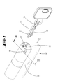
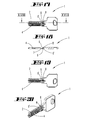
- FIGS. 1 to 16 illustrated first embodiment of the invention relates to a lock cylinder for a key 1, the key shaft 2 is coded by chest-side locking notches 3.
- the closing notches 3 are capable of sorting in a known manner against tumblers spring-loaded tumbler pins 21, 26 such that a stored in a bearing cavity 18 of a cylinder housing 17 cylinder core 24 can be rotated when the matching key 1 with its shaft 2 in the keyway 27th of the cylinder core 24 is inserted.
- the cylinder housing 17 has two axially successive bearing cavities 18, in each of which a cylinder core 24 inserted. Between the two cylinder cores 24 extends a closing member 23, which is coupled with inserted key 1 with the cylinder core 24, so that rotation of the cylinder core 24 in the bearing cavity 18, the closing member 23 rotates, so that a mortise, in which the lock cylinder inserted is, can be closed.
- the keyway 27 of the cylinder core 24 open not only the core pin holes 25, in each of which a core pin 26 is located.
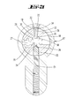
- the keyway 27 also opens at least one transverse bore 30 in which a pull pin 33 is mounted.
- the transverse bore 30 has a smaller diameter portion and a larger diameter portion 32 so that an outwardly directed step 31 is formed.
- a compression spring 38 is supported ( FIG. 3a ).
- the other end of the compression spring 38 is supported on an annular step 37 of the tension pin 33, so that a locking end 34 of the inserted in the transverse bore 30 pull pin 33 is acted upon in the direction away from the keyway 27.
- the bearing cavity 18 forms a blocking opening 19, which is closed by a plug 22 ( FIG. 3 ).
- the compression spring 38 holds the locking end 34 of the tension pin 33 in the locking opening 19. Plugs the locking end 34th in the locking opening 19, the lock cylinder can not be closed.
- the cylinder core 24 is locked in rotation.
- An end of the lock 34 opposite Switzerlandende 35 of the tension pin 33 has the shape of a truncated cone.
- a flat, circular cross-sectional end face of the substantially rotationally symmetrical pull pin 33 is opposite to a rotational symmetry-breaking inclined edge of the locking end 34.
- protrude profile ribs 28 In the keyway 27, whose width is defined by the material thickness of the shaft 2 of the matching key 1, protrude profile ribs 28. These profile ribs 28 engage in profile grooves 5 of the key shank, which profile grooves 5 have been milled into the broad side planes 6, 7 of the key shank 2 ( FIG. 5 ).
- Parallel to the keyway 27 is a parallel channel 29.
- the parallel channel 29 is open as well as the keyway 27 to the front end face of the cylinder core 24. While the keyway 27 extends over the entire axial length of the cylinder core 24, the parallel channel 29 extends only over a portion of the keyway 27th
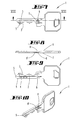
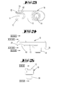
- the key 1 is made of a flat piece of metal ( FIGS. 7 to 10 ).
- the flat piece has two facing away from each broad side surfaces 6, 7, which are spaced from each other by the material thickness of the sheet ( FIG. 8 ). These two broad side surfaces 6, 7 define the key shank broadside plane. Their distance also defines the width of the key channel 27.
- the key shank 2 has a fastening opening 8 which extends from one broad side plane 6 to the other broad side plane 7.
- the mounting hole 8 may be outside the range of the key shank 2, which is in the key channel 27 in the closing state of the key 1.
- the reference numeral 10 denotes a attachment member ( FIGS. 11 to 14 ), which can be plugged onto the key broadside plane 7, and then forms a projection ( Figures 15,16 ).
- the attachment member 10 may be formed by a diecast part. It can be made of metal.
- the attachment member 10 has a base 16 which fits into the recess 9. At the base 16, a pin 14 connects, which fits into the mounting hole 8. An extension 13 forms a support surface 15 which can rest on the bottom of the recess portion 9 '.
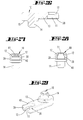
- the extension 13 is followed by a fork opening 11 ( FIGS. 11 to 14 ).
- the two fork tines flanking the fork opening 11 form pulling flanks 12 on their side pointing in the direction of the broad side plane 7.
- the pull flanks 12 are formed by inclined flanks.
- the pull flanks 12 may extend over the entire length of the forks. Preferably, they extend at an angle between 25 ° and 35 ° only over the end portion of the forks.
- the inner edge of the fork opening 11 is rounded and forms a chamfer.
- the web flank of the fork opening 11 is formed in the plan view as rounding.
- the attachment member 10 is positively inserted into the recess 9, so that the pin 14 projects into the attachment opening 8.
- the attachment member 10 may be caulked in the attachment opening 8. But it is also possible to permanently bind the attachment member 10 via an adhesive bond to the key shaft 2.
- the transverse bore 30 extends offset to a radial through the center of the cylinder core 24.
- the projection 10 is thus associated with a back of the key adjacent portion of the key shaft broadside 7.
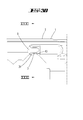
- FIG. 1 shows in a perspective view a lock cylinder with a closing member 23 which can be rotated together with the cylinder core 24 when inserted into the keyway 27 of the cylinder core 24 key 1.
- the Figures 2 . 3 and 5 It can be seen that the parallel channel 29 extends in the direction of extension of the cylinder core 24 parallel to the keyway 27.
- the walls of the parallel channel 29 are rounded.
- the parallel channel 29 can be made by two radially offset holes from the front side of the cylinder core 24 ago.
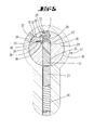
- the FIG. 3 showing the lock cylinder without key 1 inserted represents the lock state.
- the housing pin 21 projects partially into the core pin 26 receiving bore.
- the Fig. 4 shows the fully inserted into the keyway 27 key shank 2.
- the fixed to the broad side of the key shank 2 projection 10 is formed by a Aufsteckglied, which can be made of a different material than the key 1.
- the FIG. 5 shows the same cross section as the FIG. 3 shows, but with inserted into the keyway 27 key 2.
- the core pin 26 is brought by a locking notch 3 in a position in which the housing pin 21 is completely pushed out of the core pin hole 25.
- the locking end 34 of the tension pin 3 protrudes into the locking opening 19 closed by the plug 22, so that not only the housing pin 21 but also the tension pin 33 exerts a blocking function.
- the Buchende 35 of the tension pin 33 was detected by the two fork bevels 12 of the attachment member 10 and pulled in the direction of the key broadside, so that the locking end 34 is pulled out of the locking hole 19.
- FIGS. 7 to 10 show a profiled key, but which is not yet equipped with the attachment member 10. Visible is a round in cross-section hole 8, which passes through the entire key shaft 2.
- This attachment opening 8 is located in the bottom of a recess 9 and serves to receive a pin 14 of a in the FIGS. 11 to 14 A Aufsteckgliedes 10.
- a subsequent to the pin 14 queritessveriererter base 16 is in the recess 9 recording.
- a recess portion 9 'connects which extends from the recess 9 in the direction of the key tip.
- On the bottom of this recess portion 9 ' is the support surface 15 of the extension 13 of the attachment member 10. Base 16 and extension 13 are precisely in the wells 9, 9'.
- the key is designed as a turning flat key and has instead of the notch incisions 3 broad side recesses 4, which cooperate with core pins 26. Due to the point-symmetrical shape of the key shank, the key 1 is able to close the lock cylinder in positions rotated by 180 ° about the key longitudinal axis. He has on both broad sides 6, 7 each have a projection 10 which is also formed as a Aufsteckglied. The key broadsides form laterally offset holes 8 and depressions 9, 9 ', into which the attachment member 10 is inserted can be. Again, the attachment of the attachment member 10 is positively or non-positively.
- the fork opening 11 of the Aufsteckgliedes 10 is located at the rear of a profile rib of the key shank 2, the profile rib of the key shank 2 is slightly reduced in the area immediately in front of the fork opening 11, so that the lying in its blocking position completely outside the key channel 27 end face portion of the tension pin 33 in some areas the keyway 27 can be pulled.
- the transverse bore 30 extends approximately in the radial direction.
- the pull pin 33 is rotationally symmetrical.
- each of the two key broadsides in a recess 9 and in a recessed portion 9 ' carries a Aufsteckglied 10.
- the attachment members 10 are laterally offset from one another. Since the center line of the keyway 27 but radially offset relative to the center of rotation of the cylinder core 24, the parallel channel 29, in which engages the pull pin 33 engaging the attachment member 10, in the cylinder core longitudinal center, in which the core pin hole 25 is located. The pull pin 33 is therefore in the same plane in which the core pins 26 are, he is facing a core pin 26.
- the keyway 27 has two parallel channels 29, but only one parallel channel 29 is equipped with pins 33.
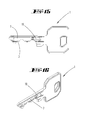
- FIG. 21 shows the lock cylinder in the locking position in which the housing pin 21 projects slightly into the core bore 25.
- the spring 38 acts on the pull pin 33 in the closed by a stopper 22 locking opening 19, so that the intervening there locking portion 34 as well as the housing pin 21, the rotation of the cylinder core 24 locks when the key is not inserted.
- FIG. 22 shows the lock cylinder with inserted matching key.
- the frustoconical Switzerlandende 35 was acted upon by the two forks and their trailing edges 12. In this case, the locking end 34 has entered the fork opening 11. Along with this, the inclined traction flanks 12 have pulled out the pull pin 33 or its blocking end 34 from the blocking opening 19.
- the core pin 26 engages only so far in a broad side recess 4 of the key shank 2, that its associated housing pin 21 is completely pushed out of the core pin hole 25.
- the cylinder core 24 can be rotated.
- the transverse bore 30 is only slightly spaced in both embodiments of the opening of the keyway 27 in the extension direction of the keyway 27.
- the blocking opening 19 or the transverse bore 30 aligned therewith is located at the axial height of the first tumbler pin pair 21, 26 in the insertion direction, so that the attachment member 10 lies partially outside the parallel channel 29 when the key is inserted completely into the keyway 27.
- the attachment member 10 is thus partially in front of the end face of the cylinder core 24.
- the parallel channel can thus have a minimum axial depth.
- the parallel channel 29 can be generated by drilling from the front side of the cylinder core 24 ago. It can be made two parallel holes that leave the above-mentioned rounded walls of the parallel channel 29.
- the centers of the two parallel holes 29 forming blind holes can lie in the lateral boundary plane of the keyway 27.
- a portion of the rounded wall of the parallel channel 29 may also extend over a protruding into the keyway 27 rib 28.
- the axial length of the parallel channel 29 is adapted to the maximum axial insertion depth of the attachment member 10.
- the attachment member 10 is also formed of brass die-cast and has a pin 14 which is inserted into a mounting opening 8 of a key shank 2 and caulked there.
- the Aufsteckteil 10 has differently than in the above-described embodiments hidden arranged obliquely extending traction edges 12th
- Walls 39 are formed which rest on the bottom of the recess 9 and which form a traction flank 12 on their inner sides pointing towards the fork opening 11.
- the pull flanks 12 are inclined in the embodiment both in the extension direction of the forks, as well as in a direction transverse thereto, ie in the forks.
- the pointing away from the key shank 2 edge edges of the attachment member 10 are rounded.
- the wall 39 is in contact, in particular in the region in which the traction flank 12 is located, on the bottom of the depression 9. From there extends an extending in the direction of the surface normal of the bottom surface end edge of the wall 39, which merges to form the rounding in the broad side surface of the Aufsteckmaschines 10.
- the recess 40 is located in the region of one of the walls 39 and has a cylindrical rounded inner surface. It can be a dome surface.
- the recess 40 is located in the region of the vertex of a notch incision 3.
- the notch incision 3 can thus extend into the region of the fork opening 11.
- the scanning tip of a core pin 26 can dip into the recess 40 and itself at the top of the notch incision 3 of the key shank 2 are supported.
- the plug-on part 10 overlaps the notch incision region by area.
- a key which is characterized in that the traction flank 12 is formed by a projection 10 projecting from the key shank broad side.
- a lock cylinder which is characterized by a parallel to the keyway 27 extending and the keyway 27 open parallel channel 29 for the entry of a protruding from the Sumschaftbreitseite projection 10 which forms the traction edge 12.
- a locking device or a key which is characterized in that the projection 10 is formed by a Aufsteckglied which is fixedly connected to the key shaft 2.
- a locking device or a key which is characterized in that the projection 10 has a fork opening 11 which is spaced from the broad side plane 7 of the key shank 2 and / or that the projection 10 forms two mutually parallel forks, between which a fork opening 11th extends to the entrance of the Switzerlandendes 35 of the tumbler pin 33rd
- a closing device or a key which is characterized in that partially over the broad side plane 7 projecting fork tines obliquely extending traction edges 12 and / or that the traction flanks 12 are flanked by walls 39 of the fork opening 11, which walls 39 on the broad side of the key shank. 2 issue.
- a locking device or a key which are characterized in that the forming the projection 10 Aufsteckglied has a pin 14 which is inserted in an opening 8 of the key shank 2.
- a locking device or a key which is characterized in that the attachment member has a base 16 from which in particular the pin 14 protrudes, the base 16 inserted in a recess 9 of the key shaft broadside and / or that of the base 16, an extension 10 in Whyeinsteckraum protrudes, wherein at the free end of the extension 10, the pulling edge 12 is arranged.
- a locking device or a key which are characterized, the key consists of a flat piece whose material thickness 2 is defined by opposite broad side planes 6, 7, wherein the projection 10 projects beyond one of the broad side planes 7 and in particular of a profile groove 5 is adjacent.
- a locking device or a lock cylinder which are characterized in that the tumbler pin designed as a pull pin 33 is acted upon by a compression spring 38 in the blocking position and / or that the compression spring 38 with its first end to a step 37 of the tension pin 33 and with its other End at a step 31 of a transverse bore 30 of the cylinder core 24 is supported.
- a closing device or a lock cylinder which is characterized in that the pull pin 33 has a substantially frustoconical Werner 35 and / or that the Werende 35 preferably in the locking position does not protrude into the keyway 27 in the release position.
- a locking device or a lock cylinder which are characterized in that the parallel channel 29 extends only over a partial extension length of the keyway 27.
- a locking device or a lock cylinder which is characterized in that the projection formed as a mounting member 10 has a forked opening 11 between two walls 39, wherein the walls 39 on their pointing to the fork opening 11 inside the traction flanks 12 form and with their away from the fork opening 11 facing outsides on the bottom of the recess 9 rest.
- a closing device or a lock cylinder which is characterized in that at least one of the walls 39 forms an outside recess 40 as clearance for entry of a section of a core pin 26, wherein the recess 40 is arranged in the region of a notch incision 3.
Landscapes
- Lock And Its Accessories (AREA)
Applications Claiming Priority (2)
| Application Number | Priority Date | Filing Date | Title |
|---|---|---|---|
| DE102013104942 | 2013-05-14 | ||
| DE102013106028.5A DE102013106028A1 (de) | 2013-05-14 | 2013-06-11 | Schließzylinder mit Zugstift, an dem ein von der Breitseite des Schlüssels abragender Vorsprung angreift |
Publications (2)
| Publication Number | Publication Date |
|---|---|
| EP2803793A2 true EP2803793A2 (fr) | 2014-11-19 |
| EP2803793A3 EP2803793A3 (fr) | 2015-07-29 |
Family
ID=50687353
Family Applications (1)
| Application Number | Title | Priority Date | Filing Date |
|---|---|---|---|
| EP14168023.1A Withdrawn EP2803793A3 (fr) | 2013-05-14 | 2014-05-13 | Barillet doté d'une tige de tension, sur laquelle vient en prise une protubérance en saillie à partir du côté plat de la clé |
Country Status (2)
| Country | Link |
|---|---|
| EP (1) | EP2803793A3 (fr) |
| DE (1) | DE102013106028A1 (fr) |
Cited By (4)
| Publication number | Priority date | Publication date | Assignee | Title |
|---|---|---|---|---|
| CN106760985A (zh) * | 2016-12-25 | 2017-05-31 | 广东炬森五金精密制造有限公司 | 一种双灵动叶片锁芯 |
| CN112673143A (zh) * | 2018-09-13 | 2021-04-16 | 塔莱雷斯·埃斯科瑞扎公司 | 具有钥匙和锁芯的锁系统 |
| EP4261366A1 (fr) * | 2022-04-14 | 2023-10-18 | dormakaba Schweiz AG | Élément clé, cylindre de serrure, système de fermeture et procédé |
| DE102022127486A1 (de) * | 2022-07-25 | 2024-01-25 | C.Ed. Schulte Gesellschaft mit beschränkter Haftung Zylinderschlossfabrik | Schließsystem bestehend aus einem Schließzylinder und einem passenden Schlüssel |
Families Citing this family (3)
| Publication number | Priority date | Publication date | Assignee | Title |
|---|---|---|---|---|
| US11536047B1 (en) * | 2022-08-22 | 2022-12-27 | Winloc Ag | Key plug, a cylinder lock, a cylinder lock and key combination and a method to manufacture a key plug |
| US11542724B1 (en) * | 2022-08-22 | 2023-01-03 | Winloc Ag | Key blank, a key, and a cylinder lock and key combination |
| US11613909B1 (en) * | 2022-08-22 | 2023-03-28 | Winloc Ag | Key blank, a coded key and a cylinder lock and key system with improved stop arrangement |
Citations (3)
| Publication number | Priority date | Publication date | Assignee | Title |
|---|---|---|---|---|
| DE3225952A1 (de) | 1982-07-10 | 1984-01-12 | Karrenberg, Wilhelm, 5620 Velbert | Schliesszylinder-flachschluessel |
| DE69818428T2 (de) | 1997-01-29 | 2004-07-01 | International Security Products Inc., Southington | Zylinderschlosssystem |
| DE102004021580B3 (de) | 2004-05-03 | 2005-11-10 | Wilka Schließtechnik GmbH | Aus Schlüssel und Schließzylinder bestehende Schließvorrichtung |
Family Cites Families (3)
| Publication number | Priority date | Publication date | Assignee | Title |
|---|---|---|---|---|
| US5819566A (en) * | 1997-01-29 | 1998-10-13 | International Security Products, Inc. | Cylinder lock and key |
| DE102010017166B4 (de) * | 2010-05-31 | 2013-03-07 | C.Ed. Schulte Gesellschaft mit beschränkter Haftung Zylinderschlossfabrik | Verfahren zum Profilieren eines Flachschlüssels sowie nach dem Verfahren gefertigter Flachschlüssel |
| US8820129B2 (en) * | 2011-10-12 | 2014-09-02 | Moshe Dolev | Cylinder lock assembly with non-rotating elements |
-
2013
- 2013-06-11 DE DE102013106028.5A patent/DE102013106028A1/de not_active Withdrawn
-
2014
- 2014-05-13 EP EP14168023.1A patent/EP2803793A3/fr not_active Withdrawn
Patent Citations (3)
| Publication number | Priority date | Publication date | Assignee | Title |
|---|---|---|---|---|
| DE3225952A1 (de) | 1982-07-10 | 1984-01-12 | Karrenberg, Wilhelm, 5620 Velbert | Schliesszylinder-flachschluessel |
| DE69818428T2 (de) | 1997-01-29 | 2004-07-01 | International Security Products Inc., Southington | Zylinderschlosssystem |
| DE102004021580B3 (de) | 2004-05-03 | 2005-11-10 | Wilka Schließtechnik GmbH | Aus Schlüssel und Schließzylinder bestehende Schließvorrichtung |
Cited By (9)
| Publication number | Priority date | Publication date | Assignee | Title |
|---|---|---|---|---|
| CN106760985A (zh) * | 2016-12-25 | 2017-05-31 | 广东炬森五金精密制造有限公司 | 一种双灵动叶片锁芯 |
| CN106760985B (zh) * | 2016-12-25 | 2023-08-04 | 广东炬森五金精密制造有限公司 | 一种双灵动叶片锁芯 |
| CN112673143A (zh) * | 2018-09-13 | 2021-04-16 | 塔莱雷斯·埃斯科瑞扎公司 | 具有钥匙和锁芯的锁系统 |
| EP4261366A1 (fr) * | 2022-04-14 | 2023-10-18 | dormakaba Schweiz AG | Élément clé, cylindre de serrure, système de fermeture et procédé |
| WO2023198351A1 (fr) * | 2022-04-14 | 2023-10-19 | Dormakaba Schweiz Ag | Élément de clé, barillet de serrure, système de verrouillage et procédé |
| CH719611A1 (de) * | 2022-04-14 | 2023-10-31 | Dormakaba Schweiz Ag | Schlüsselelement, Schliesszylinder, Schliesssystem und Verfahren zur Herstellung eines Schlüsselelements. |
| AU2023254345B2 (en) * | 2022-04-14 | 2025-02-27 | Dormakaba Schweiz Ag | Key element, lock cylinder, locking system, and method |
| US12607038B2 (en) | 2022-04-14 | 2026-04-21 | Dormakaba Schweiz Ag | Key element, lock cylinder, locking system, and method |
| DE102022127486A1 (de) * | 2022-07-25 | 2024-01-25 | C.Ed. Schulte Gesellschaft mit beschränkter Haftung Zylinderschlossfabrik | Schließsystem bestehend aus einem Schließzylinder und einem passenden Schlüssel |
Also Published As
| Publication number | Publication date |
|---|---|
| DE102013106028A1 (de) | 2014-11-20 |
| EP2803793A3 (fr) | 2015-07-29 |
Similar Documents
| Publication | Publication Date | Title |
|---|---|---|
| EP2803793A2 (fr) | Barillet doté d'une tige de tension, sur laquelle vient en prise une protubérance en saillie à partir du côté plat de la clé | |
| DE3051010C2 (fr) | ||
| EP2314807B1 (fr) | Système de verrouillage | |
| DE102013203151A1 (de) | Betonschraube | |
| EP3409865B1 (fr) | Cylindre de fermeture doté d'une clé correspondante | |
| EP3045621A1 (fr) | Barillet, cle et ebauche de cle | |
| DE69818428T2 (de) | Zylinderschlosssystem | |
| DE102010012261B4 (de) | Schließsystem | |
| EP2998471A1 (fr) | Cle et cylindre de fermeture rotatif dote de cle | |
| EP3535824B1 (fr) | Support de jeu de barres et ensemble correspondant | |
| DE102009025993B3 (de) | Schließeinrichtung sowie Schlüssel für eine Schließeinrichtung | |
| DE102007038254B4 (de) | Kupplungsglied für eine Mitnehmerkupplung und Herstellungsverfahren | |
| EP1975353A1 (fr) | Armature destinée à verrouiller des fenêtres ou des portes | |
| EP2360334B1 (fr) | Cylindre de fermeture | |
| DE602004005630T2 (de) | Schraubdübel | |
| EP2792822B1 (fr) | Codage via des poutres de blocage | |
| EP4237197B1 (fr) | Insert de tournevis | |
| EP2317040B1 (fr) | Clé pour serrure cylindrique | |
| DE102016102288A1 (de) | Schlüssel für einen Schließzylinder, Schließzylinder und Schließvorrichtung | |
| DE20105519U1 (de) | Zylinderschloß mit Zylindergehäuse und Flachschlüssel für ein Zylinderschloß | |
| EP3085860B1 (fr) | Dispositif de fermeture | |
| CH710832A1 (de) | Programmierbarer Schliesszylinder. | |
| EP4678857A1 (fr) | Clé dotée d'un élément de codage alimenté par ressort, serrure cylindrique avec protection contre le percage et dispositif de fermetureavec clé et serrure cylindrique | |
| EP3483364A1 (fr) | Clé d'actionnement d'un cylindre de serrure et système de fermeture à clé et à cylindre de serrure | |
| DE19940728A1 (de) | Profilstift für Türdrücker |
Legal Events
| Date | Code | Title | Description |
|---|---|---|---|
| PUAI | Public reference made under article 153(3) epc to a published international application that has entered the european phase |
Free format text: ORIGINAL CODE: 0009012 |
|
| 17P | Request for examination filed |
Effective date: 20140513 |
|
| AK | Designated contracting states |
Kind code of ref document: A2 Designated state(s): AL AT BE BG CH CY CZ DE DK EE ES FI FR GB GR HR HU IE IS IT LI LT LU LV MC MK MT NL NO PL PT RO RS SE SI SK SM TR |
|
| AX | Request for extension of the european patent |
Extension state: BA ME |
|
| PUAL | Search report despatched |
Free format text: ORIGINAL CODE: 0009013 |
|
| AK | Designated contracting states |
Kind code of ref document: A3 Designated state(s): AL AT BE BG CH CY CZ DE DK EE ES FI FR GB GR HR HU IE IS IT LI LT LU LV MC MK MT NL NO PL PT RO RS SE SI SK SM TR |
|
| AX | Request for extension of the european patent |
Extension state: BA ME |
|
| RIC1 | Information provided on ipc code assigned before grant |
Ipc: E05B 27/00 20060101AFI20150619BHEP Ipc: E05B 19/06 20060101ALI20150619BHEP |
|
| STAA | Information on the status of an ep patent application or granted ep patent |
Free format text: STATUS: THE APPLICATION IS DEEMED TO BE WITHDRAWN |
|
| 18D | Application deemed to be withdrawn |
Effective date: 20160130 |