EP2803794A2 - Unité de verrouillage électromécanique pour le domaine automobile - Google Patents
Unité de verrouillage électromécanique pour le domaine automobile Download PDFInfo
- Publication number
- EP2803794A2 EP2803794A2 EP14168363.1A EP14168363A EP2803794A2 EP 2803794 A2 EP2803794 A2 EP 2803794A2 EP 14168363 A EP14168363 A EP 14168363A EP 2803794 A2 EP2803794 A2 EP 2803794A2
- Authority
- EP
- European Patent Office
- Prior art keywords
- gear
- locking unit
- lock
- movement
- electromechanical locking
- Prior art date
- Legal status (The legal status is an assumption and is not a legal conclusion. Google has not performed a legal analysis and makes no representation as to the accuracy of the status listed.)
- Granted
Links
Images

Classifications
-
- B—PERFORMING OPERATIONS; TRANSPORTING
- B60—VEHICLES IN GENERAL
- B60R—VEHICLES, VEHICLE FITTINGS, OR VEHICLE PARTS, NOT OTHERWISE PROVIDED FOR
- B60R25/00—Fittings or systems for preventing or indicating unauthorised use or theft of vehicles
- B60R25/01—Fittings or systems for preventing or indicating unauthorised use or theft of vehicles operating on vehicle systems or fittings, e.g. on doors, seats or windscreens
- B60R25/02—Fittings or systems for preventing or indicating unauthorised use or theft of vehicles operating on vehicle systems or fittings, e.g. on doors, seats or windscreens operating on the steering mechanism
-
- E—FIXED CONSTRUCTIONS
- E05—LOCKS; KEYS; WINDOW OR DOOR FITTINGS; SAFES
- E05B—LOCKS; ACCESSORIES THEREFOR; HANDCUFFS
- E05B77/00—Vehicle locks characterised by special functions or purposes
- E05B77/36—Noise prevention; Anti-rattling means
- E05B77/38—Cushion elements, elastic guiding elements or holding elements, e.g. for cushioning or damping the impact of the bolt against the striker during closing of the wing
-
- E—FIXED CONSTRUCTIONS
- E05—LOCKS; KEYS; WINDOW OR DOOR FITTINGS; SAFES
- E05B—LOCKS; ACCESSORIES THEREFOR; HANDCUFFS
- E05B77/00—Vehicle locks characterised by special functions or purposes
- E05B77/42—Means for damping the movement of lock parts, e.g. slowing down the return movement of a handle
-
- E—FIXED CONSTRUCTIONS
- E05—LOCKS; KEYS; WINDOW OR DOOR FITTINGS; SAFES
- E05B—LOCKS; ACCESSORIES THEREFOR; HANDCUFFS
- E05B81/00—Power-actuated vehicle locks
- E05B81/02—Power-actuated vehicle locks characterised by the type of actuators used
- E05B81/04—Electrical
- E05B81/06—Electrical using rotary motors
-
- E—FIXED CONSTRUCTIONS
- E05—LOCKS; KEYS; WINDOW OR DOOR FITTINGS; SAFES
- E05B—LOCKS; ACCESSORIES THEREFOR; HANDCUFFS
- E05B81/00—Power-actuated vehicle locks
- E05B81/24—Power-actuated vehicle locks characterised by constructional features of the actuator or the power transmission
- E05B81/32—Details of the actuator transmission
- E05B81/34—Details of the actuator transmission of geared transmissions
-
- E—FIXED CONSTRUCTIONS
- E05—LOCKS; KEYS; WINDOW OR DOOR FITTINGS; SAFES
- E05B—LOCKS; ACCESSORIES THEREFOR; HANDCUFFS
- E05B81/00—Power-actuated vehicle locks
- E05B81/24—Power-actuated vehicle locks characterised by constructional features of the actuator or the power transmission
- E05B81/32—Details of the actuator transmission
- E05B81/42—Cams
- E05B81/44—Cams in the form of grooves
-
- E—FIXED CONSTRUCTIONS
- E05—LOCKS; KEYS; WINDOW OR DOOR FITTINGS; SAFES
- E05B—LOCKS; ACCESSORIES THEREFOR; HANDCUFFS
- E05B83/00—Vehicle locks specially adapted for particular types of wing or vehicle
- E05B83/28—Locks for glove compartments, console boxes, fuel inlet covers or the like
- E05B83/34—Locks for glove compartments, console boxes, fuel inlet covers or the like for fuel inlet covers essentially flush with the vehicle surface
-
- E—FIXED CONSTRUCTIONS
- E05—LOCKS; KEYS; WINDOW OR DOOR FITTINGS; SAFES
- E05B—LOCKS; ACCESSORIES THEREFOR; HANDCUFFS
- E05B85/00—Details of vehicle locks not provided for in groups E05B77/00 - E05B83/00
- E05B85/20—Bolts or detents
- E05B85/22—Rectilinearly moving bolts
-
- E—FIXED CONSTRUCTIONS
- E05—LOCKS; KEYS; WINDOW OR DOOR FITTINGS; SAFES
- E05B—LOCKS; ACCESSORIES THEREFOR; HANDCUFFS
- E05B15/00—Other details of locks; Parts for engagement by bolts of fastening devices
- E05B15/04—Spring arrangements in locks
- E05B2015/0403—Wound springs
- E05B2015/0406—Wound springs wound in a cylindrical shape
- E05B2015/0413—Wound springs wound in a cylindrical shape loaded by compression
Definitions
- the present invention relates to an electromechanical locking unit for the vehicle sector.
- electromechanical locking units are in use, for example, as a steering lock to prevent a steering column rotation in the locked state of a vehicle, as a door, window or flap lock for doors, windows, tailgate or tank lid of a vehicle, and - in the context of current developments of alternative drive concepts - Also for locking charging plugs of electrical charging cables or fuel dispensers for gas, hydrogen or methane refueling.
- vehicle area includes all types of motor vehicles - automobiles, trucks, two-wheelers, etc. - and including each including those with internal combustion engine, electric drive and combinations of different drive concepts (hybrid drives).
- Electromechanical locking units in charge plugs of electrical charging cables or hydrogen refueling are also both on the side of the power supply stations such as gas stations or charging stations, as well as integrated in the respective plugs or sockets of the connecting lines between the vehicle and power supply stations in use.
- Characteristic for the use of the locking units in the vehicle sector are the demands for compact dimensions, after very short operating times, after high holding forces, for functional safety even in extreme environmental conditions such as Moisture and large temperature differences, and not least for cost-effective production.
- an electromechanical locking device for electric vehicles for locking and unlocking a charging cable connector to a charging cable socket which has an electric motor as a drive source and a locking mechanism by which the driving force of the electric motor is transmitted by means of a mechanical gear train on a serving as a locking member movable locking pin, the is moved between a locking position and an unlocked position.
- the mechanical gear train includes a screw fixed to and driven by the output shaft of the electric motor, which meshes with and rotates a tooth on the outer circumference of a worm wheel.
- a control cam On the worm wheel in turn a control cam is formed, which transmits the rotational movement of the worm wheel in a linear movement of a guided by the control cam driver and then on the locking pin.
- the entire locking device is encapsulated in a housing and forms a locking unit, which is installed in the charging cable connector so that the locking pin protrudes in the locking position of the plug and engages in a recess in the charging cable socket, so that the charging cable without the activation of the locking device is not off the charging cable socket can be pulled out.
- a very similar working electromechanical locking device is in the DE 10109609 C1 discloses and serves in the variant described there for the mechanical locking of the steering spindle of a motor vehicle.
- actuation of the electric motor of this locking device is activated and moves the locking pin in the locking position, in which it engages in a locking ring on the steering shaft.
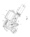
- FIG. 9 Another similar electromechanical locking unit for a charging cable for electric vehicles is in the DE 102011050998 A1 described and in the Fig. 1 shown.
- a housing 9 an electric motor 2 and a gear with a directly driven by the electric motor 2 screw 2.1 and a worm wheel 4 are housed, which is seen with a toothing 4.3 on the outer circumference and with the screw 2.1 is engaged.
- the worm wheel 4 is mounted for rotation about a rotation axis 4.2 and has axially on one end face a sprial-shaped link or track 4.1, with a guide element 3.1 of a locking member 3 is engaged.
- the guide element 3.1 can only move in the radial direction, whereby a rotation of the guide track 4.1 upon rotation of the worm wheel 4 causes a linear movement of the guide element 3.1 and thus of the locking member 3.
- the reference numeral 18,19 switch for detecting certain movement positions of the worm wheel and the locking member are indicated.
- the locking units described above by way of example have in common that they - for use in the vehicle sector typically - with a very small size a relatively heavy and stable locking pin very quickly between the two end positions (locking position and unlocking position) must be able to reciprocate linearly. This is achieved by using a very fast rotating electric motor and a gear train according to the above description, which converts the high speed of the motor with a corresponding reduction in the also fast but vo the movement distance much shorter linear motion of the locking pin.
- the movement of the moving elements of the gear train and / or the engine must be stopped very abruptly. This can be done either by modulating the drive signal of the motor over Positioner is triggered before reaching the end positions and causes a defined deceleration of the motor, or can be achieved by assigning a fixed mechanical stop to a suitable moving element of the gear train, which blocks its movement at the defined end position.
- the first solution is relatively complex and therefore costly, because it requires the additional position sensors and a complex control, but it largely avoids force peaks and pulses.
- the second solution is simpler, but leads to high force peaks and self-locking gearboxes to a blockage, and in particular over time to damage to the stop surfaces and the engagement portions of the gear train. So far, this can only be counteracted by dispensing with simple plastic parts, which increases costs, or by correspondingly robust designs. With the numerous locking units per vehicle and the high volume of mass producers, however, even low cost savings while ensuring high operational reliability are of crucial importance.
- the object of the present invention is to provide an electromechanical locking unit for use in the vehicle sector, in particular as a charging connector lock or steering lock, which enables cost-effective manufacturability a fast and reliable braking of the electric motor or the locking member in the end positions of the same.
- the invention also relates to a charging connector lock according to claim 9 and a Steering lock according to claim 10, each having the locking unit according to the invention.
- an electric motor and a locking mechanism comprising a locking member, e.g. a locking pin, and a gear train, e.g. a worm gear for transmitting a driving force from the electric motor to the locking member to move it between a locking position and an unlocking position.
- At least one movement element in the locking mechanism is associated with a mechanical stop which blocks its movement at a defined end position which corresponds to the respective end position of the locking element.
- the stop and / or the movement element have an elastic element, which is mechanically deformable before reaching the defined end position by the engagement with the movement element in order to delay the movement of the movement element without pronounced force peak.
- the deformation of the elastic element before reaching the end position absorbs the kinetic energy more gently than the fixed or rigid stop, dampens the mechanical impulse and avoids a high force peak.
- the individual elements of the gear train do not have to have such high strengths, so that in spite of dispensing with a complicated motor control, it is also possible to use simple plastic parts with high durability.
- the size of the unit can be smaller, which the integrability of e.g. relieved in a charging plug or a charging socket.
- the elastic element can have both a linear elastic or a progressive-elastic behavior.
- the behavior can be influenced by using a material with the appropriate modulus of elasticity or, in the case of a spring, with a corresponding spring characteristic.
- the elastic element may be an elastically deformable material body, in particular made of an elastic plastic, rubber or other material may be, or be a spring, such as a spiral spring such as a leaf or a spiral spring.
- the movement element which is associated with the elastic element, a gear in the gear train, such as the worm wheel in a transmission, as in the DE 102011050998 A1 is described
- the spring is a preferably round bending or spiral spring, which is arranged around a rotation axis of the gear around so that a leg of the bending or spiral spring before reaching the end position of the gear (corresponding to an end position of the locking pin), in Engaged with a fixed stop and thereby elastically deformed.
- the elastic deformation leads to a damped deceleration of the gear before the end position.
- the bending or spiral spring is also preferably arranged on the gear that decreases with the deformation of the diameter of the bending or spiral spring and the inner circumference of the spring at a defined deformation with a fixed surface, in particular a concentric with the gear housing flange in Frictional contact passes, whereby an additional delay is exerted on the gear. This achieves a progressive delay.
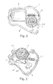
- FIGS. 2 to 5 show a locking unit according to the invention in different views and partial representations, which from the DE 102011050998 A1 known locking unit according to Fig. 1 is very similar. Some components such as locking member and terminal contacts are omitted in the illustration for clarity. In this respect, and with respect to the common elements such as engine and transmission, which are provided with the identical reference numerals, is on the representation and description of Fig. 1 directed.
- an electric motor 2 is also provided here, which drives a gear (worm wheel) 4 via a worm 2.1.
- the gear is by means of a (not shown) guide element of a locking member which moves in a guide curve 4.1 of the gear 4, the rotation in a linear movement of the locking member to.
- the gear train thus formed and the individual movement elements thereof are of course only exemplary and more or fewer movement elements can be provided.
- the gear 4 is approximately pot-shaped and has at its in Fig. 2 unobservable but in the 4 and 5 shown bottom instead of a rigid stop, an elastic member 6, which cooperates with a rigid stopper 5, which is connected as a projection with the housing 9 or integrally formed, as will be explained below.
- the housing-side stop 5 defines together with the elastic element 6, the end positions of the rotational movement of the gear.
- this is elastic element 6 is a round spiral spring made of a flat metal band, which is bent into a circle and has at the ends radially outwardly bent legs 6.1 and 6.2. The free distance between the legs defines the maximum possible distance of movement 6.3 of the respective leg and thus the maximum possible deformation of the spring.
- the one leg is 6.1 a radially outwardly straight bent end of the metal strip while the other stop 6.2 is formed by the other end is first bent radially outward, then in the circumferential direction and finally again radially inward and so a total of about U-shaped structure possesses.
- the shape of the thighs is, however, customizable.
- the round spiral spring is inserted into a hub-like projection 4.3 of the gear 4.
- one or the other leg of the spiral spring at a certain rotational position in engagement with one of the stop surfaces of the rigid stopper 5 of the housing. From this point, the bending spring is deformed during further rotation of the gear by this leg is moved to the other leg. In this case, the diameter of the spiral spring and the outer peripheral surface of the spiral spring decreases partially from the system on the hub-like projection 4.3 of the gear from.
- the inner peripheral surface of the spiral spring then engages an outer peripheral surface of a gear concentric fixed hub-like flange 8 of the housing 9, whereby a frictional force is generated, which counteracts the rotational movement of the gear.
- the pressing force of the spring on the flange 8 of the housing and thus the frictional force becomes larger.
- Both the elasticity of the spiral spring and the frictional force lead to a gentle or slow onset delaying the rotation of the gear to a stop - at the latest when one leg rests against the other leg.
- This embodiment can also be modified by completely dispensing with the additional frictional force or by using a different shaped spring.
- Concentric spiral springs made of round wire, coil springs or mechanical springs, which are arranged in the gear that they are simply compressed by the engagement with the stop of the housing, are also conceivable.
- an elastic material body made of rubber or a plastic can be used instead of the mechanical spring.
- the component generally referred to herein as an "elastic member” may also be provided at or in lieu of the stop of the housing, while the gear has a fixed or rigid stop in the working area, for example in the form of a web formed or fixed to the underside.
- an elastic element can be provided on each of the two elements-that is to say on the toothed wheel and on the housing stop.
- the elastic member is not limited to the gear and may be provided on each of the moving elements in the gear train including the locking member.
- the gear offers at the worm gear, because it is the largest component and covers a relatively long circumferential distance between the two end positions, so that there is sufficient space for installation of the stops and the elastic element.
- both end position sensors or switches for detecting the position of the locking member as well as a complex control for the engine, which evaluates their signals and modulates the drive signal of the motor when approaching the end positions are dispensed with.
- the elements of the gear train are protected against force peaks when reaching the end positions, so that the components can be produced inexpensively and have a long life.
- the additional required elastic element is demgegnüber very cheap, be it as an elastic material body or as a bending spring.
- the elastic elements also provide protection against mechanical vibrations and impacts from outside. This advantage is particularly important when using the locking unit in charging plugs or sockets of charging cables for electric vehicles, because they are handled manually and are therefore often exposed to improper treatment.
Landscapes
- Engineering & Computer Science (AREA)
- Mechanical Engineering (AREA)
- Lock And Its Accessories (AREA)
Applications Claiming Priority (1)
| Application Number | Priority Date | Filing Date | Title |
|---|---|---|---|
| DE102013008550.0A DE102013008550A1 (de) | 2013-05-16 | 2013-05-16 | Elektromechanische Verriegelungseinheit für den Fahrzeugbereich |
Publications (3)
| Publication Number | Publication Date |
|---|---|
| EP2803794A2 true EP2803794A2 (fr) | 2014-11-19 |
| EP2803794A3 EP2803794A3 (fr) | 2015-07-01 |
| EP2803794B1 EP2803794B1 (fr) | 2019-03-27 |
Family
ID=50732819
Family Applications (1)
| Application Number | Title | Priority Date | Filing Date |
|---|---|---|---|
| EP14168363.1A Not-in-force EP2803794B1 (fr) | 2013-05-16 | 2014-05-14 | Unité de verrouillage électromécanique pour le domaine automobile |
Country Status (2)
| Country | Link |
|---|---|
| EP (1) | EP2803794B1 (fr) |
| DE (1) | DE102013008550A1 (fr) |
Cited By (7)
| Publication number | Priority date | Publication date | Assignee | Title |
|---|---|---|---|---|
| CN108429074A (zh) * | 2018-03-21 | 2018-08-21 | 王和能 | 用于新能源汽车充电接口的斜接式触发机构 |
| CN108461990A (zh) * | 2018-03-21 | 2018-08-28 | 王和能 | 用于新能源汽车快充接口的锁紧机构 |
| CN109659769A (zh) * | 2018-12-15 | 2019-04-19 | 国网福建省电力有限公司检修分公司 | 变电站接地线闭锁实现装置及其工作方法 |
| CN111749555A (zh) * | 2020-06-17 | 2020-10-09 | 温州市东风通用机电厂 | 一种汽车闭锁器 |
| CN112761437A (zh) * | 2019-10-21 | 2021-05-07 | 开开特股份公司 | 机动车锁,尤其是机动车门锁 |
| WO2022117155A1 (fr) * | 2020-12-02 | 2022-06-09 | Kiekert Ag | Unité de verrouillage électromotrice de dispositif de charge électrique de véhicule à moteur |
| US20240068277A1 (en) * | 2022-08-29 | 2024-02-29 | Inteva Products, Llc | Power release latch with impact reducer feature |
Families Citing this family (3)
| Publication number | Priority date | Publication date | Assignee | Title |
|---|---|---|---|---|
| CN109972937B (zh) | 2017-12-27 | 2022-05-10 | 伊利诺斯工具制品有限公司 | 加油或充电口门锁总成 |
| DE102020132027A1 (de) | 2020-12-02 | 2022-06-02 | Kiekert Aktiengesellschaft | Elektromotorische Antriebseinheit für kraftfahrzeug-technische Anwendungen |
| DE102021128976A1 (de) | 2021-11-08 | 2023-05-11 | Kiekert Aktiengesellschaft | Kraftfahrzeug-technische Stellvorrichtung |
Citations (2)
| Publication number | Priority date | Publication date | Assignee | Title |
|---|---|---|---|---|
| DE10109609C1 (de) | 2001-02-28 | 2002-10-10 | Huf Huelsbeck & Fuerst Gmbh | Schloß, insbesondere zum Verriegeln der Lenkspindel eines Kraftfahrzeugs |
| DE102011050998A1 (de) | 2011-06-09 | 2012-06-14 | Huf Hülsbeck & Fürst Gmbh & Co. Kg | Verriegelungsvorrichtung für elektrische Ladekabel |
Family Cites Families (7)
| Publication number | Priority date | Publication date | Assignee | Title |
|---|---|---|---|---|
| DE2923447A1 (de) * | 1979-06-09 | 1980-12-11 | Fichtel & Sachs Ag | Antrieb fuer eine schliess- und/oder verriegelungseinrichtung an einer fahrzeugtuere |
| DE3418802C2 (de) * | 1984-05-19 | 1986-03-06 | Kiekert GmbH & Co KG, 5628 Heiligenhaus | Vorrichtung zur Betätigung eines Kraftfahrzeug-Türverschlusses |
| IT219355Z2 (it) * | 1990-03-29 | 1993-02-22 | Dispositivo perfezionato per l'azionamento delle sicurezze delle porte di un autoveicolo per sistemi centralizzati di comando | |
| FR2768869B1 (fr) * | 1997-09-22 | 1999-12-03 | Rockwell Lvs | Actionneur electrique de condamnation pour serrure de vehicule |
| FR2877977B1 (fr) * | 2004-11-12 | 2007-01-19 | Arvinmeritor Light Vehicle Sys | Serrure de vehicule automobile |
| DE202004020261U1 (de) * | 2004-12-28 | 2006-05-11 | Brose Schließsysteme GmbH & Co.KG | Antriebseinrichtung zur motorischen Verstellung eines Funktionselements in einem Kraftfahrzeug |
| JP5682004B2 (ja) * | 2010-05-11 | 2015-03-11 | 三井金属アクト株式会社 | 車両用ラッチ装置 |
-
2013
- 2013-05-16 DE DE102013008550.0A patent/DE102013008550A1/de not_active Withdrawn
-
2014
- 2014-05-14 EP EP14168363.1A patent/EP2803794B1/fr not_active Not-in-force
Patent Citations (2)
| Publication number | Priority date | Publication date | Assignee | Title |
|---|---|---|---|---|
| DE10109609C1 (de) | 2001-02-28 | 2002-10-10 | Huf Huelsbeck & Fuerst Gmbh | Schloß, insbesondere zum Verriegeln der Lenkspindel eines Kraftfahrzeugs |
| DE102011050998A1 (de) | 2011-06-09 | 2012-06-14 | Huf Hülsbeck & Fürst Gmbh & Co. Kg | Verriegelungsvorrichtung für elektrische Ladekabel |
Cited By (11)
| Publication number | Priority date | Publication date | Assignee | Title |
|---|---|---|---|---|
| CN108429074A (zh) * | 2018-03-21 | 2018-08-21 | 王和能 | 用于新能源汽车充电接口的斜接式触发机构 |
| CN108461990A (zh) * | 2018-03-21 | 2018-08-28 | 王和能 | 用于新能源汽车快充接口的锁紧机构 |
| CN109659769A (zh) * | 2018-12-15 | 2019-04-19 | 国网福建省电力有限公司检修分公司 | 变电站接地线闭锁实现装置及其工作方法 |
| CN112761437A (zh) * | 2019-10-21 | 2021-05-07 | 开开特股份公司 | 机动车锁,尤其是机动车门锁 |
| CN112761437B (zh) * | 2019-10-21 | 2023-09-19 | 开开特股份公司 | 机动车锁,尤其是机动车门锁 |
| CN111749555A (zh) * | 2020-06-17 | 2020-10-09 | 温州市东风通用机电厂 | 一种汽车闭锁器 |
| CN111749555B (zh) * | 2020-06-17 | 2023-05-26 | 温州市东风通用机电厂 | 一种汽车闭锁器 |
| WO2022117155A1 (fr) * | 2020-12-02 | 2022-06-09 | Kiekert Ag | Unité de verrouillage électromotrice de dispositif de charge électrique de véhicule à moteur |
| JP2023553857A (ja) * | 2020-12-02 | 2023-12-26 | キーケルト アクツィーエンゲゼルシャフト | 自動車の充電装置の為の電動式ロックユニット |
| US12594847B2 (en) | 2020-12-02 | 2026-04-07 | Kiekert Ag | Electromotive locking unit for an electrical charging device of a motor vehicle |
| US20240068277A1 (en) * | 2022-08-29 | 2024-02-29 | Inteva Products, Llc | Power release latch with impact reducer feature |
Also Published As
| Publication number | Publication date |
|---|---|
| EP2803794A3 (fr) | 2015-07-01 |
| DE102013008550A1 (de) | 2014-11-20 |
| EP2803794B1 (fr) | 2019-03-27 |
Similar Documents
| Publication | Publication Date | Title |
|---|---|---|
| EP2803794B1 (fr) | Unité de verrouillage électromécanique pour le domaine automobile | |
| EP2668062B1 (fr) | Dispositif de verrouillage, notamment pour un connecteur | |
| EP2734395B1 (fr) | Dispositif de verrouillage de bouchon de réservoir à nombre réduit d'éléments | |
| EP2826938B1 (fr) | Serrure de véhicule automobile | |
| EP2705202A1 (fr) | Dispositif de verrouillage et siège de véhicule | |
| DE102010029446A1 (de) | Stellantrieb für ein Kraftfahrzeug | |
| DE102009014312A1 (de) | Elektromotorischer Hilfsantrieb, insbesondere Wischerantrieb | |
| EP2800117A1 (fr) | Unité d'actionnement | |
| DE19861276B4 (de) | Spindel- oder Schneckenantrieb für Verstelleinrichtungen in Kraftfahrzeugen | |
| DE102007059710B4 (de) | Kompakte Verriegelungsvorrichtung mit Sicherungselement | |
| EP1295748B1 (fr) | Actionneur de volet d'obturation d'une baie de carosserie | |
| DE19712185C1 (de) | Antriebsvorrichtung für ein verstellbares Teil eines Fahrzeuges | |
| DE102007028957A1 (de) | Aktuator für insbesondere Kraftfahrzeugtürschlösser | |
| EP2556266B1 (fr) | Dispositif de blocage de couple de charge et unité équipée d'un dispositif de blocage de couple de charge | |
| EP2483553A1 (fr) | Dispositif de démarrage à amortissement de bruit optimisé | |
| WO2011110377A2 (fr) | Dispositif d'entraînement comportant un moteur d'entraînement électrique et une transmission | |
| WO2012130206A2 (fr) | Dispositif de verrouillage pour un véhicule à moteur | |
| EP2229493B1 (fr) | Système de verrouillage de porte de véhicule automobile | |
| DE102007023389A1 (de) | Wellenanlaufanordnung; Stellantrieb sowie Fensterhebereinrichtung | |
| EP2117887B1 (fr) | Dispositif d'asservissement d'un organe de blocage | |
| WO2014067820A1 (fr) | Dispositif d'entraînement destiné à un élément réglable d'un véhicule | |
| DE102009058612A1 (de) | Elektromechanische Fahrzeuglenkung | |
| DE102012102814B4 (de) | Scheibenwischermotor | |
| DE102018109039A1 (de) | Stelleinheit für kraftfahrzeugtechnische Anwendungen | |
| DE102009010088A1 (de) | Reversibler Gurtstraffer |
Legal Events
| Date | Code | Title | Description |
|---|---|---|---|
| PUAI | Public reference made under article 153(3) epc to a published international application that has entered the european phase |
Free format text: ORIGINAL CODE: 0009012 |
|
| 17P | Request for examination filed |
Effective date: 20140514 |
|
| AK | Designated contracting states |
Kind code of ref document: A2 Designated state(s): AL AT BE BG CH CY CZ DE DK EE ES FI FR GB GR HR HU IE IS IT LI LT LU LV MC MK MT NL NO PL PT RO RS SE SI SK SM TR |
|
| AX | Request for extension of the european patent |
Extension state: BA ME |
|
| PUAL | Search report despatched |
Free format text: ORIGINAL CODE: 0009013 |
|
| AK | Designated contracting states |
Kind code of ref document: A3 Designated state(s): AL AT BE BG CH CY CZ DE DK EE ES FI FR GB GR HR HU IE IS IT LI LT LU LV MC MK MT NL NO PL PT RO RS SE SI SK SM TR |
|
| AX | Request for extension of the european patent |
Extension state: BA ME |
|
| RIC1 | Information provided on ipc code assigned before grant |
Ipc: E05B 83/34 20140101ALI20150522BHEP Ipc: E05B 81/44 20140101ALI20150522BHEP Ipc: B60R 25/02 20130101ALI20150522BHEP Ipc: E05B 81/06 20140101AFI20150522BHEP Ipc: E05B 77/42 20140101ALI20150522BHEP Ipc: E05B 85/22 20140101ALI20150522BHEP Ipc: E05B 81/34 20140101ALI20150522BHEP |
|
| R17P | Request for examination filed (corrected) |
Effective date: 20151215 |
|
| RBV | Designated contracting states (corrected) |
Designated state(s): AL AT BE BG CH CY CZ DE DK EE ES FI FR GB GR HR HU IE IS IT LI LT LU LV MC MK MT NL NO PL PT RO RS SE SI SK SM TR |
|
| GRAP | Despatch of communication of intention to grant a patent |
Free format text: ORIGINAL CODE: EPIDOSNIGR1 |
|
| STAA | Information on the status of an ep patent application or granted ep patent |
Free format text: STATUS: GRANT OF PATENT IS INTENDED |
|
| RIC1 | Information provided on ipc code assigned before grant |
Ipc: B60R 25/02 20130101ALI20180906BHEP Ipc: E05B 81/06 20140101AFI20180906BHEP Ipc: E05B 15/04 20060101ALI20180906BHEP Ipc: E05B 81/44 20140101ALI20180906BHEP Ipc: E05B 77/42 20140101ALI20180906BHEP Ipc: E05B 83/34 20140101ALI20180906BHEP Ipc: E05B 81/34 20140101ALI20180906BHEP Ipc: E05B 85/22 20140101ALI20180906BHEP Ipc: E05B 77/38 20140101ALI20180906BHEP |
|
| INTG | Intention to grant announced |
Effective date: 20181002 |
|
| GRAS | Grant fee paid |
Free format text: ORIGINAL CODE: EPIDOSNIGR3 |
|
| GRAA | (expected) grant |
Free format text: ORIGINAL CODE: 0009210 |
|
| STAA | Information on the status of an ep patent application or granted ep patent |
Free format text: STATUS: THE PATENT HAS BEEN GRANTED |
|
| AK | Designated contracting states |
Kind code of ref document: B1 Designated state(s): AL AT BE BG CH CY CZ DE DK EE ES FI FR GB GR HR HU IE IS IT LI LT LU LV MC MK MT NL NO PL PT RO RS SE SI SK SM TR |
|
| REG | Reference to a national code |
Ref country code: GB Ref legal event code: FG4D Free format text: NOT ENGLISH |
|
| REG | Reference to a national code |
Ref country code: CH Ref legal event code: EP |
|
| REG | Reference to a national code |
Ref country code: AT Ref legal event code: REF Ref document number: 1113283 Country of ref document: AT Kind code of ref document: T Effective date: 20190415 |
|
| REG | Reference to a national code |
Ref country code: IE Ref legal event code: FG4D Free format text: LANGUAGE OF EP DOCUMENT: GERMAN |
|
| REG | Reference to a national code |
Ref country code: DE Ref legal event code: R096 Ref document number: 502014011214 Country of ref document: DE |
|
| PG25 | Lapsed in a contracting state [announced via postgrant information from national office to epo] |
Ref country code: NO Free format text: LAPSE BECAUSE OF FAILURE TO SUBMIT A TRANSLATION OF THE DESCRIPTION OR TO PAY THE FEE WITHIN THE PRESCRIBED TIME-LIMIT Effective date: 20190627 Ref country code: LT Free format text: LAPSE BECAUSE OF FAILURE TO SUBMIT A TRANSLATION OF THE DESCRIPTION OR TO PAY THE FEE WITHIN THE PRESCRIBED TIME-LIMIT Effective date: 20190327 Ref country code: SE Free format text: LAPSE BECAUSE OF FAILURE TO SUBMIT A TRANSLATION OF THE DESCRIPTION OR TO PAY THE FEE WITHIN THE PRESCRIBED TIME-LIMIT Effective date: 20190327 Ref country code: FI Free format text: LAPSE BECAUSE OF FAILURE TO SUBMIT A TRANSLATION OF THE DESCRIPTION OR TO PAY THE FEE WITHIN THE PRESCRIBED TIME-LIMIT Effective date: 20190327 |
|
| REG | Reference to a national code |
Ref country code: NL Ref legal event code: MP Effective date: 20190327 |
|
| PG25 | Lapsed in a contracting state [announced via postgrant information from national office to epo] |
Ref country code: LV Free format text: LAPSE BECAUSE OF FAILURE TO SUBMIT A TRANSLATION OF THE DESCRIPTION OR TO PAY THE FEE WITHIN THE PRESCRIBED TIME-LIMIT Effective date: 20190327 Ref country code: RS Free format text: LAPSE BECAUSE OF FAILURE TO SUBMIT A TRANSLATION OF THE DESCRIPTION OR TO PAY THE FEE WITHIN THE PRESCRIBED TIME-LIMIT Effective date: 20190327 Ref country code: BG Free format text: LAPSE BECAUSE OF FAILURE TO SUBMIT A TRANSLATION OF THE DESCRIPTION OR TO PAY THE FEE WITHIN THE PRESCRIBED TIME-LIMIT Effective date: 20190627 Ref country code: GR Free format text: LAPSE BECAUSE OF FAILURE TO SUBMIT A TRANSLATION OF THE DESCRIPTION OR TO PAY THE FEE WITHIN THE PRESCRIBED TIME-LIMIT Effective date: 20190628 Ref country code: NL Free format text: LAPSE BECAUSE OF FAILURE TO SUBMIT A TRANSLATION OF THE DESCRIPTION OR TO PAY THE FEE WITHIN THE PRESCRIBED TIME-LIMIT Effective date: 20190327 Ref country code: HR Free format text: LAPSE BECAUSE OF FAILURE TO SUBMIT A TRANSLATION OF THE DESCRIPTION OR TO PAY THE FEE WITHIN THE PRESCRIBED TIME-LIMIT Effective date: 20190327 |
|
| PG25 | Lapsed in a contracting state [announced via postgrant information from national office to epo] |
Ref country code: ES Free format text: LAPSE BECAUSE OF FAILURE TO SUBMIT A TRANSLATION OF THE DESCRIPTION OR TO PAY THE FEE WITHIN THE PRESCRIBED TIME-LIMIT Effective date: 20190327 Ref country code: PT Free format text: LAPSE BECAUSE OF FAILURE TO SUBMIT A TRANSLATION OF THE DESCRIPTION OR TO PAY THE FEE WITHIN THE PRESCRIBED TIME-LIMIT Effective date: 20190727 Ref country code: AL Free format text: LAPSE BECAUSE OF FAILURE TO SUBMIT A TRANSLATION OF THE DESCRIPTION OR TO PAY THE FEE WITHIN THE PRESCRIBED TIME-LIMIT Effective date: 20190327 Ref country code: SK Free format text: LAPSE BECAUSE OF FAILURE TO SUBMIT A TRANSLATION OF THE DESCRIPTION OR TO PAY THE FEE WITHIN THE PRESCRIBED TIME-LIMIT Effective date: 20190327 Ref country code: IT Free format text: LAPSE BECAUSE OF FAILURE TO SUBMIT A TRANSLATION OF THE DESCRIPTION OR TO PAY THE FEE WITHIN THE PRESCRIBED TIME-LIMIT Effective date: 20190327 Ref country code: EE Free format text: LAPSE BECAUSE OF FAILURE TO SUBMIT A TRANSLATION OF THE DESCRIPTION OR TO PAY THE FEE WITHIN THE PRESCRIBED TIME-LIMIT Effective date: 20190327 Ref country code: CZ Free format text: LAPSE BECAUSE OF FAILURE TO SUBMIT A TRANSLATION OF THE DESCRIPTION OR TO PAY THE FEE WITHIN THE PRESCRIBED TIME-LIMIT Effective date: 20190327 Ref country code: RO Free format text: LAPSE BECAUSE OF FAILURE TO SUBMIT A TRANSLATION OF THE DESCRIPTION OR TO PAY THE FEE WITHIN THE PRESCRIBED TIME-LIMIT Effective date: 20190327 |
|
| PG25 | Lapsed in a contracting state [announced via postgrant information from national office to epo] |
Ref country code: PL Free format text: LAPSE BECAUSE OF FAILURE TO SUBMIT A TRANSLATION OF THE DESCRIPTION OR TO PAY THE FEE WITHIN THE PRESCRIBED TIME-LIMIT Effective date: 20190327 Ref country code: SM Free format text: LAPSE BECAUSE OF FAILURE TO SUBMIT A TRANSLATION OF THE DESCRIPTION OR TO PAY THE FEE WITHIN THE PRESCRIBED TIME-LIMIT Effective date: 20190327 |
|
| REG | Reference to a national code |
Ref country code: CH Ref legal event code: PL |
|
| PG25 | Lapsed in a contracting state [announced via postgrant information from national office to epo] |
Ref country code: IS Free format text: LAPSE BECAUSE OF FAILURE TO SUBMIT A TRANSLATION OF THE DESCRIPTION OR TO PAY THE FEE WITHIN THE PRESCRIBED TIME-LIMIT Effective date: 20190727 |
|
| REG | Reference to a national code |
Ref country code: DE Ref legal event code: R097 Ref document number: 502014011214 Country of ref document: DE |
|
| PG25 | Lapsed in a contracting state [announced via postgrant information from national office to epo] |
Ref country code: MC Free format text: LAPSE BECAUSE OF FAILURE TO SUBMIT A TRANSLATION OF THE DESCRIPTION OR TO PAY THE FEE WITHIN THE PRESCRIBED TIME-LIMIT Effective date: 20190327 Ref country code: DK Free format text: LAPSE BECAUSE OF FAILURE TO SUBMIT A TRANSLATION OF THE DESCRIPTION OR TO PAY THE FEE WITHIN THE PRESCRIBED TIME-LIMIT Effective date: 20190327 Ref country code: CH Free format text: LAPSE BECAUSE OF NON-PAYMENT OF DUE FEES Effective date: 20190531 Ref country code: LI Free format text: LAPSE BECAUSE OF NON-PAYMENT OF DUE FEES Effective date: 20190531 |
|
| REG | Reference to a national code |
Ref country code: BE Ref legal event code: MM Effective date: 20190531 |
|
| PLBE | No opposition filed within time limit |
Free format text: ORIGINAL CODE: 0009261 |
|
| STAA | Information on the status of an ep patent application or granted ep patent |
Free format text: STATUS: NO OPPOSITION FILED WITHIN TIME LIMIT |
|
| GBPC | Gb: european patent ceased through non-payment of renewal fee |
Effective date: 20190627 |
|
| PG25 | Lapsed in a contracting state [announced via postgrant information from national office to epo] |
Ref country code: LU Free format text: LAPSE BECAUSE OF NON-PAYMENT OF DUE FEES Effective date: 20190514 Ref country code: SI Free format text: LAPSE BECAUSE OF FAILURE TO SUBMIT A TRANSLATION OF THE DESCRIPTION OR TO PAY THE FEE WITHIN THE PRESCRIBED TIME-LIMIT Effective date: 20190327 |
|
| 26N | No opposition filed |
Effective date: 20200103 |
|
| PG25 | Lapsed in a contracting state [announced via postgrant information from national office to epo] |
Ref country code: TR Free format text: LAPSE BECAUSE OF FAILURE TO SUBMIT A TRANSLATION OF THE DESCRIPTION OR TO PAY THE FEE WITHIN THE PRESCRIBED TIME-LIMIT Effective date: 20190327 |
|
| PG25 | Lapsed in a contracting state [announced via postgrant information from national office to epo] |
Ref country code: GB Free format text: LAPSE BECAUSE OF NON-PAYMENT OF DUE FEES Effective date: 20190627 Ref country code: IE Free format text: LAPSE BECAUSE OF NON-PAYMENT OF DUE FEES Effective date: 20190514 |
|
| PG25 | Lapsed in a contracting state [announced via postgrant information from national office to epo] |
Ref country code: BE Free format text: LAPSE BECAUSE OF NON-PAYMENT OF DUE FEES Effective date: 20190531 |
|
| PG25 | Lapsed in a contracting state [announced via postgrant information from national office to epo] |
Ref country code: FR Free format text: LAPSE BECAUSE OF NON-PAYMENT OF DUE FEES Effective date: 20190527 |
|
| REG | Reference to a national code |
Ref country code: AT Ref legal event code: MM01 Ref document number: 1113283 Country of ref document: AT Kind code of ref document: T Effective date: 20190514 |
|
| PG25 | Lapsed in a contracting state [announced via postgrant information from national office to epo] |
Ref country code: AT Free format text: LAPSE BECAUSE OF NON-PAYMENT OF DUE FEES Effective date: 20190514 |
|
| PG25 | Lapsed in a contracting state [announced via postgrant information from national office to epo] |
Ref country code: CY Free format text: LAPSE BECAUSE OF FAILURE TO SUBMIT A TRANSLATION OF THE DESCRIPTION OR TO PAY THE FEE WITHIN THE PRESCRIBED TIME-LIMIT Effective date: 20190327 |
|
| PG25 | Lapsed in a contracting state [announced via postgrant information from national office to epo] |
Ref country code: HU Free format text: LAPSE BECAUSE OF FAILURE TO SUBMIT A TRANSLATION OF THE DESCRIPTION OR TO PAY THE FEE WITHIN THE PRESCRIBED TIME-LIMIT; INVALID AB INITIO Effective date: 20140514 Ref country code: MT Free format text: LAPSE BECAUSE OF FAILURE TO SUBMIT A TRANSLATION OF THE DESCRIPTION OR TO PAY THE FEE WITHIN THE PRESCRIBED TIME-LIMIT Effective date: 20190327 |
|
| PGFP | Annual fee paid to national office [announced via postgrant information from national office to epo] |
Ref country code: DE Payment date: 20210525 Year of fee payment: 8 |
|
| PG25 | Lapsed in a contracting state [announced via postgrant information from national office to epo] |
Ref country code: MK Free format text: LAPSE BECAUSE OF FAILURE TO SUBMIT A TRANSLATION OF THE DESCRIPTION OR TO PAY THE FEE WITHIN THE PRESCRIBED TIME-LIMIT Effective date: 20190327 |
|
| REG | Reference to a national code |
Ref country code: DE Ref legal event code: R119 Ref document number: 502014011214 Country of ref document: DE |
|
| PG25 | Lapsed in a contracting state [announced via postgrant information from national office to epo] |
Ref country code: DE Free format text: LAPSE BECAUSE OF NON-PAYMENT OF DUE FEES Effective date: 20221201 |