EP2803801B1 - Actionneur rotatif électrique pour un dispositif d'entrée et de sortie, en particulier une porte - Google Patents
Actionneur rotatif électrique pour un dispositif d'entrée et de sortie, en particulier une porte Download PDFInfo
- Publication number
- EP2803801B1 EP2803801B1 EP13425076.0A EP13425076A EP2803801B1 EP 2803801 B1 EP2803801 B1 EP 2803801B1 EP 13425076 A EP13425076 A EP 13425076A EP 2803801 B1 EP2803801 B1 EP 2803801B1
- Authority
- EP
- European Patent Office
- Prior art keywords
- shaft
- decoupler
- rotating column
- motor
- door
- Prior art date
- Legal status (The legal status is an assumption and is not a legal conclusion. Google has not performed a legal analysis and makes no representation as to the accuracy of the status listed.)
- Active
Links
Images


Classifications
-
- E—FIXED CONSTRUCTIONS
- E05—LOCKS; KEYS; WINDOW OR DOOR FITTINGS; SAFES
- E05F—DEVICES FOR MOVING WINGS INTO OPEN OR CLOSED POSITION; CHECKS FOR WINGS; WING FITTINGS NOT OTHERWISE PROVIDED FOR, CONCERNED WITH THE FUNCTIONING OF THE WING
- E05F15/00—Power-operated mechanisms for wings
- E05F15/40—Safety devices, e.g. detection of obstructions or end positions
-
- E—FIXED CONSTRUCTIONS
- E05—LOCKS; KEYS; WINDOW OR DOOR FITTINGS; SAFES
- E05F—DEVICES FOR MOVING WINGS INTO OPEN OR CLOSED POSITION; CHECKS FOR WINGS; WING FITTINGS NOT OTHERWISE PROVIDED FOR, CONCERNED WITH THE FUNCTIONING OF THE WING
- E05F15/00—Power-operated mechanisms for wings
- E05F15/60—Power-operated mechanisms for wings using electrical actuators
- E05F15/603—Power-operated mechanisms for wings using electrical actuators using rotary electromotors
-
- B—PERFORMING OPERATIONS; TRANSPORTING
- B60—VEHICLES IN GENERAL
- B60J—WINDOWS, WINDSCREENS, NON-FIXED ROOFS, DOORS, OR SIMILAR DEVICES FOR VEHICLES; REMOVABLE EXTERNAL PROTECTIVE COVERINGS SPECIALLY ADAPTED FOR VEHICLES
- B60J5/00—Doors
-
- E—FIXED CONSTRUCTIONS
- E05—LOCKS; KEYS; WINDOW OR DOOR FITTINGS; SAFES
- E05F—DEVICES FOR MOVING WINGS INTO OPEN OR CLOSED POSITION; CHECKS FOR WINGS; WING FITTINGS NOT OTHERWISE PROVIDED FOR, CONCERNED WITH THE FUNCTIONING OF THE WING
- E05F15/00—Power-operated mechanisms for wings
- E05F15/50—Power-operated mechanisms for wings using fluid-pressure actuators
- E05F15/53—Power-operated mechanisms for wings using fluid-pressure actuators for swinging wings
-
- E—FIXED CONSTRUCTIONS
- E05—LOCKS; KEYS; WINDOW OR DOOR FITTINGS; SAFES
- E05F—DEVICES FOR MOVING WINGS INTO OPEN OR CLOSED POSITION; CHECKS FOR WINGS; WING FITTINGS NOT OTHERWISE PROVIDED FOR, CONCERNED WITH THE FUNCTIONING OF THE WING
- E05F15/00—Power-operated mechanisms for wings
- E05F15/60—Power-operated mechanisms for wings using electrical actuators
- E05F15/603—Power-operated mechanisms for wings using electrical actuators using rotary electromotors
- E05F15/611—Power-operated mechanisms for wings using electrical actuators using rotary electromotors for swinging wings
- E05F15/614—Power-operated mechanisms for wings using electrical actuators using rotary electromotors for swinging wings operated by meshing gear wheels, one of which being mounted at the wing pivot axis; operated by a motor acting directly on the wing pivot axis
-
- E—FIXED CONSTRUCTIONS
- E05—LOCKS; KEYS; WINDOW OR DOOR FITTINGS; SAFES
- E05F—DEVICES FOR MOVING WINGS INTO OPEN OR CLOSED POSITION; CHECKS FOR WINGS; WING FITTINGS NOT OTHERWISE PROVIDED FOR, CONCERNED WITH THE FUNCTIONING OF THE WING
- E05F15/00—Power-operated mechanisms for wings
- E05F15/70—Power-operated mechanisms for wings with automatic actuation
-
- H—ELECTRICITY
- H02—GENERATION; CONVERSION OR DISTRIBUTION OF ELECTRIC POWER
- H02K—DYNAMO-ELECTRIC MACHINES
- H02K7/00—Arrangements for handling mechanical energy structurally associated with dynamo-electric machines, e.g. structural association with mechanical driving motors or auxiliary dynamo-electric machines
- H02K7/10—Structural association with clutches, brakes, gears, pulleys or mechanical starters
- H02K7/112—Structural association with clutches, brakes, gears, pulleys or mechanical starters with friction clutches in combination with brakes
- H02K7/1125—Magnetically influenced friction clutches and brakes
-
- H—ELECTRICITY
- H02—GENERATION; CONVERSION OR DISTRIBUTION OF ELECTRIC POWER
- H02K—DYNAMO-ELECTRIC MACHINES
- H02K7/00—Arrangements for handling mechanical energy structurally associated with dynamo-electric machines, e.g. structural association with mechanical driving motors or auxiliary dynamo-electric machines
- H02K7/10—Structural association with clutches, brakes, gears, pulleys or mechanical starters
- H02K7/116—Structural association with clutches, brakes, gears, pulleys or mechanical starters with gears
-
- E—FIXED CONSTRUCTIONS
- E05—LOCKS; KEYS; WINDOW OR DOOR FITTINGS; SAFES
- E05D—HINGES OR SUSPENSION DEVICES FOR DOORS, WINDOWS OR WINGS
- E05D15/00—Suspension arrangements for wings
- E05D15/28—Suspension arrangements for wings supported on arms movable in horizontal plane
- E05D15/30—Suspension arrangements for wings supported on arms movable in horizontal plane with pivoted arms and sliding guides
-
- E—FIXED CONSTRUCTIONS
- E05—LOCKS; KEYS; WINDOW OR DOOR FITTINGS; SAFES
- E05F—DEVICES FOR MOVING WINGS INTO OPEN OR CLOSED POSITION; CHECKS FOR WINGS; WING FITTINGS NOT OTHERWISE PROVIDED FOR, CONCERNED WITH THE FUNCTIONING OF THE WING
- E05F15/00—Power-operated mechanisms for wings
- E05F15/60—Power-operated mechanisms for wings using electrical actuators
- E05F15/603—Power-operated mechanisms for wings using electrical actuators using rotary electromotors
- E05F15/611—Power-operated mechanisms for wings using electrical actuators using rotary electromotors for swinging wings
- E05F15/63—Power-operated mechanisms for wings using electrical actuators using rotary electromotors for swinging wings operated by swinging arms
-
- E—FIXED CONSTRUCTIONS
- E05—LOCKS; KEYS; WINDOW OR DOOR FITTINGS; SAFES
- E05Y—INDEXING SCHEME ASSOCIATED WITH SUBCLASSES E05D AND E05F, RELATING TO CONSTRUCTION ELEMENTS, ELECTRIC CONTROL, POWER SUPPLY, POWER SIGNAL OR TRANSMISSION, USER INTERFACES, MOUNTING OR COUPLING, DETAILS, ACCESSORIES, AUXILIARY OPERATIONS NOT OTHERWISE PROVIDED FOR, APPLICATION THEREOF
- E05Y2201/00—Constructional elements; Accessories therefor
- E05Y2201/20—Brakes; Disengaging means; Holders; Stops; Valves; Accessories therefor
- E05Y2201/214—Disengaging means
-
- E—FIXED CONSTRUCTIONS
- E05—LOCKS; KEYS; WINDOW OR DOOR FITTINGS; SAFES
- E05Y—INDEXING SCHEME ASSOCIATED WITH SUBCLASSES E05D AND E05F, RELATING TO CONSTRUCTION ELEMENTS, ELECTRIC CONTROL, POWER SUPPLY, POWER SIGNAL OR TRANSMISSION, USER INTERFACES, MOUNTING OR COUPLING, DETAILS, ACCESSORIES, AUXILIARY OPERATIONS NOT OTHERWISE PROVIDED FOR, APPLICATION THEREOF
- E05Y2400/00—Electronic control; Electrical power; Power supply; Power or signal transmission; User interfaces
- E05Y2400/10—Electronic control
- E05Y2400/30—Electronic control of motors
- E05Y2400/3013—Electronic control of motors during manual wing operation
- E05Y2400/3017—Safety means therefor
-
- E—FIXED CONSTRUCTIONS
- E05—LOCKS; KEYS; WINDOW OR DOOR FITTINGS; SAFES
- E05Y—INDEXING SCHEME ASSOCIATED WITH SUBCLASSES E05D AND E05F, RELATING TO CONSTRUCTION ELEMENTS, ELECTRIC CONTROL, POWER SUPPLY, POWER SIGNAL OR TRANSMISSION, USER INTERFACES, MOUNTING OR COUPLING, DETAILS, ACCESSORIES, AUXILIARY OPERATIONS NOT OTHERWISE PROVIDED FOR, APPLICATION THEREOF
- E05Y2900/00—Application of doors, windows, wings or fittings thereof
- E05Y2900/50—Application of doors, windows, wings or fittings thereof for vehicles
- E05Y2900/506—Application of doors, windows, wings or fittings thereof for vehicles for buses
-
- E—FIXED CONSTRUCTIONS
- E05—LOCKS; KEYS; WINDOW OR DOOR FITTINGS; SAFES
- E05Y—INDEXING SCHEME ASSOCIATED WITH SUBCLASSES E05D AND E05F, RELATING TO CONSTRUCTION ELEMENTS, ELECTRIC CONTROL, POWER SUPPLY, POWER SIGNAL OR TRANSMISSION, USER INTERFACES, MOUNTING OR COUPLING, DETAILS, ACCESSORIES, AUXILIARY OPERATIONS NOT OTHERWISE PROVIDED FOR, APPLICATION THEREOF
- E05Y2900/00—Application of doors, windows, wings or fittings thereof
- E05Y2900/50—Application of doors, windows, wings or fittings thereof for vehicles
- E05Y2900/51—Application of doors, windows, wings or fittings thereof for vehicles for railway cars or mass transit vehicles
Definitions
- the present invention relates to a rotary actuator for moving a door with an orientable or roto-translatable shutter, in particular for public transport means, e.g., buses and trains.
- the orientable shutter of a vehicle door for example, of a bus, is connected by orientable arms, or directly, to a rotating column, and it is displaceable, through a rotatory movement of the rotating column, from an opening position to a closure position.
- the movement of the rotating column occurs through a rotary actuator with an outer housing constrained to the vehicle structure and an output shaft supported in the outer housing and connected to the rotating column integrally in rotation. Therefore, the movement of the shutter occurs in response to a rotation of the output shaft, while the housing is stationary.
- the use is known, of a rotary actuator with a pneumatic linear actuator and a screw transmission converting the linear movement of the linear actuator into a rotatory movement of the output shaft.
- the movement of the rotating column occurs through a rotary actuator with an outer housing that forms itself the rotating column or that is constrained integrally in rotation with the rotating column, as well as with a stationary shaft supported in the outer housing and constrained to the structure of the vehicle.
- the movement of the shutter here occurs in response to a rotation of the outer housing, while the shaft is stationary.
- the known electric rotary actuators are provided with an automatic locking brake that is permanently elastically pushed in a locking position to maintain the closure of the door when the electric actuator is turned off, and electrically releasable during the operation of the rotary actuator.
- the electric rotary actuators have to be provided with a mechanical emergency opening device that, in the case of electric power interruption, allows opening the door in spite of the impossibility to release the locking brake , compare DE202008011200U1 which is a closest prior art for the present invention.
- Rotary actuators have to develop high closure torques, indicatively ranging between 120Nm ... 250Nm, to oppose violent impacts due to acts of vandalism, in addition to the fluid-dynamic depression tending to open the doors, especially on extra-urban transport means traveling at high speeds.
- the object of the present invention is to provide a rotary electric actuator for moving an orientable or roto-translatable door, in particular for public transport vehicles, having such characteristics as to at least partially obviate the drawbacks of the prior art.
- a rotary actuator for an entry/exit device in particular an orientable and/or translatable door or ramp and the like in public transport vehicles, comprising an electric motor, a reduction gear arranged on a front side of the motor and connected to a front portion of a shaft of the motor, an output shaft connected to the reduction gear, an automatic locking brake arranged on a rear side of the motor opposite the front side and connected to a rear portion of the motor shaft, as well as a decoupler connected between the rear portion of the motor shaft and the locking brake, and actuatable to decouple the motor shaft from the locking brake.
- the torque creating the friction between the decoupler components is reduced in the order of the reduction ratio of at least one first reduction stage, about 1:25, and consequently the manual uncoupling force (Bowden force) is considerably reduced and easily applicable also by the elderly, children, and women.
- the transmission ratio, from the motor to the door rotating column is about 600...700 : 1, consequently the torque of the motor (and the locking torque of the brake) is about 600... 700 times less than the closure torque of the door.
- the ideal point for an easy (start of) uncoupling is to decouple the locking brake from the motor.
- the actuator comprises a second decoupler connected between the reduction gear and the output shaft and actuatable to decouple the output shaft from the second reduction gear, in which the second decoupler can be actuated following the actuation of the first decoupler.
- the output shaft 8 can be manually uncoupled from the entire motor 3 - first reduction gear 4 - second reduction gear 5 unit, for further promoting the opening of the door 2 by a simple manual push.
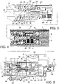
- a rotary actuator 1 for an entry/exit device in particular an orientable and/or translatable door or ramp 2 and the like in public transport vehicles, comprises an electric motor 3, a first reduction gear 4 arranged on a front side of the motor 3 and connected to a front portion 6 of a shaft 7 of the motor 3, a second reduction gear 5 connected to the first reduction gear 4, an output shaft 8 connected to the second reduction gear 5, an automatic locking brake 9 arranged on a rear side of the motor 3 opposite the front side and connected to a rear portion 10 of the motor shaft 7, as well as a decoupler 11 connected between the rear portion 10 of the motor shaft 7 and the locking brake 9 and actuatable to decouple the motor shaft 7 from the locking brake 9.
- the actuator 1 comprises a second decoupler 12 connected between the second reduction gear 5 and the output shaft 8 and actuatable to decouple the output shaft 8 from the second reduction gear 5.
- the output shaft 8 can be manually uncoupled from the entire motor 3 - first reduction gear 4 - second reduction gear 5 unit, for further promoting the opening of the door 2 by a simple manual push.
- the rotary actuator 1 comprises an unlocking mechanism 13 actuatable manually and configured so as to first actuate the first decoupler 11 and then the second decoupler 12.
- the invention contemplates a method for uncoupling the output shaft 8 from the locking brake 9, comprising the steps of:
- the unlocking mechanism 13 comprises a Bowden cable 14 connected to the first decoupler 11 and to at least one tie-rod 15, in turn connected to the second decoupler 12.
- the first decoupler 11 comprises a first shaft 16 (connected to the motor shaft 7) having a tubular wall 17 forming an inner cavity and one or more (preferably three) locking cavities 18, a second tubular shaft 19 (connected to the locking brake 9) and received into the inner cavity of the tubular wall 17 rotatably about a rotational axis R and forming one or more through openings 20 in a position suitable to overlap with the through openings 18.
- One or more locking members 21 are received in the through openings 20 of the second shaft 19, for example rolling members, rollers, spheres, etc., displaceable between a radially outer position in engagement with the through opening 20 and with the locking cavity 18, preventing the relative rotation between the first shaft 16 and the second shaft 19, and a radially inner position outside the locking cavities 18, allowing the relative rotation between the first shaft 16 and the second shaft 19.
- a control bar 22 is inserted in the second tubular shaft 19, which is axially slidable between a locking position and a release position, and having a control surface 23 facing the through openings 20 and shaped so that, when the control bar 22 is in the locking position, the control surface 23 locks the locking members 21 in the radially outer position, and, when the control bar 22 is in the release position, the control surface 23 allows displacing the locking members 21 in the radially inner position.
- the control bar 22 is permanently elastically urged in the locking position, for example by a first spring 24 received in the second tubular shaft 19 and abutting with precompression between a shoulder of the control bar 22 and an abutting surface of the second shaft 19.
- a rear end 25 of the control bar 22 is connected to a Bowden connector 26.
- the Bowden connector 26 is slidably supported parallel to the rotational axis R and in turn connected with the end of an inner cable of the Bowden cable 14, the outer sheath of which is constrained to a support structure 27 of the actuator 1.
- the traction of the Bowden cable 14 moves the control bar 22, opposing the elastic force of the first spring 24, from the locking position to the release position, allowing the relative rotation between the first and the second shafts and, therefore, between the locking brake 9 and the motor shaft 7.
- the first spring 24 pushes the control bar 22 towards the locking position and, by rotating the first shaft 16 relative to the second shaft 17 until overlapping the locking cavities 18 with the through openings 20, the locking members 21 can come back to the radially outer position, where they are again locked by the control surface 23 of the control bar 22. In this manner, the first and the second shafts and, thus, the locking brake and the motor shaft are again coupled integrally in rotation.
- the terms “to uncouple” and “uncoupling” refer to a “uncoupling of the rotary motion" of the two components between which the decoupler is connected, and not necessarily to a complete separation or moving of the two "uncoupled” components away from one another.
- the first shaft 16 in the “coupled” condition the first shaft 16 is constrained integrally in rotation to the second shaft 19, whereby the two shafts rotate together and can transmit a torsion.
- the first shaft 16 In the "uncoupled” condition, the first shaft 16 can rotate relative to the second shaft 19, whereby the two shafts are not able to transmit a torsion (except for the torsion due to residual frictions).
- the second decoupler 12 comprises a first shaft 28 (connected to the second reduction gear 5) having a tubular wall 29 forming an inner cavity and one or more (preferably 5) through openings 30, a second shaft 31 (connected to the output shaft 8 or forming a portion of the output shaft 8) and received into the inner cavity of the tubular wall 29 rotatably about a rotational axis R and forming one or more locking cavities 32 in a position suitable to overlap with the through openings 30.
- One or more locking members 33 are received in the through openings 30 of the second shaft 31, for example rolling members, rollers, spheres, etc., displaceable between a radially inner position in engagement with the through opening 30 and with the locking cavity 32, preventing the relative rotation between the first shaft 28 and the second shaft 31, and a radially outer position outside the locking cavities 32, allowing the relative rotation between the first shaft 28 and the second shaft 31.
- a driving sleeve 34 is inserted on the tubular wall 29 of the first shaft 28, which is axially slidable between a locking position and a release position and having a control surface 35 facing the through openings 30 and shaped so that, when the driving sleeve 34 is in the locking position, the control surface 35 locks the locking members 33 in the radially inner position, and, when the driving sleeve 34 is in the release position, the control surface 35 allows displacing the locking members 33 in the radially outer position.
- the driving sleeve 34 is permanently elastically urged in the locking position, for example by a second spring 36 abutting with precompression between a shoulder of the driving sleeve 34 and an abutting surface of the first shaft 28.
- a thrust portion 37 is connected with the Bowden connector 26, e.g., by one or more tie-rods 15 extending externally along the reduction gears 4, 5 and the motor 3, and configured (i.e., positioned and shaped) so that:
- the second spring 36 pushes the driving sleeve 34 towards the locking position and, by rotating the first shaft 28 relative to the second shaft 31 until overlapping the locking cavities 32 with the through openings 30, the locking members 33 can come back to the radially inner position, where they are locked again by the control surface 35 of the driving sleeve 34. In this manner, the first and the second shafts and, thus, the reduction gear 4, 5 and the output shaft 8 are coupled again integrally in rotation.
- the thrust portion 37 can also be urged permanently elastically in a position thereof disengaged from the driving sleeve 34, for example, by a third spring 52 abutting with precompression between the thrust portion 37 and the support structure 27.
- a rotating column 38 is rotatably constrained to a frame 42 of the door 2 and one or more orientable arms 39 are connected integrally in rotation to the rotating column 38 to move (open and close) a shutter 40 of the door 2 in response to a rotation of the rotating column 38.
- the rotary actuator 1 is at least partially inserted within the rotating column 38 and (with the support structure 27 or at least the motor 3 body) constrained integrally in rotation to the frame 39 (preferably to an upper support 51 of the rotating column 38), while the output shaft 8 is connected to transmit the rotary motion thereof to the rotating column 39, for example, by a direct rotation-preventing connection 41 or by a transmission gear (not shown).
- the locking brake 9 is arranged externally to the rotating column 38 (and preferably above an upper support 51 thereof) and connected to the motor shaft 7 through a transmission portion extending from the interior of the rotating column 38 to the exterior thereof.
- Such transmission portion can be formed, for example, by the first shaft 16 of the first decoupler 11.
- the locking brake 9 outside the rotating column 38 can be arranged in a not co-axial or aligned manner with the rest of the actuator 1, for example, within the so-called cabinets above the doors of the autobus.
- a sensor 44 for detecting a position and/or angular speed of the motor shaft for example, a potentiometer or a Hall effect sensor, of the absolute or relative type, can be arranged externally to the rotating column 38 (and preferably above an upper support 51 thereof).
- the electric supply cables and the Bowden cable do not move during the rotating column 38 rotation, and are less prone to wearing; furthermore, they can be better secured and hidden.
- the rotary actuator 1 is preferably inserted in an upper part of the rotating column 38.
- the components are joined together by the support structure 27 and insertable/withdrawable together into the/from the rotating column 38 on a single side, preferably the upper side thereof. This obviates the need of disassembling the entire rotating column 38 in the case of maintenance or replacement of the actuator 1.
- the reduction gears 4, 5 preferably comprise epicycloidal gears, in which the material resistance and the number of the planet wheels of the second reduction gear 5 are larger than the material resistance and of the number of the planet wheels of the first reduction gear 4.
- the nominal torque produced by and transmissible from the output shaft 8 to the rotating column 38 may be 120Nm, while the maximum torque may be about 250Nm.
- the first reduction gear 4 can be an epicycloidal gear with two reductions stages (first, or initial, stage 45, second stage 46) with a transmission ratio of 1:28, and the second reduction gear 5 can be an epicycloidal gear with two reductions stages (third stage 47, fifth stage 48, or end stage) with a transmission ratio of 1:24.
- the output shaft of the final reduction stage 48 may be broached (toothed) and directly fitted in the rotating column 38 to apply the rotation with an overall reduction ratio of 1:675 with respect to the motor shaft 7.
- An upper arm of the orientable arms 39 driving the movement of the door 2 shutter 40 can be mounted integrally in rotation and translation to the rotating column 38, as shown in Fig. 5 or, alternatively, the orientable arm 39 can be fitted with the rotating column 38 integrally in rotation, but translatable or adjustable in height, for example by an axial guide welded to the rotating column 38 (not shown).
- An upper support 51 of the rotating column 38 may comprise an oscillating joint 50, adjustable transversally to the rotational axis 49 of the rotating column 38 and lockable in the desired adjustment position.
- the outer sheaths of the at least one, preferably two Bowden cables 14 may be secured to such upper support 51.
Landscapes
- Engineering & Computer Science (AREA)
- Power Engineering (AREA)
- Mechanical Engineering (AREA)
- Lock And Its Accessories (AREA)
- Power-Operated Mechanisms For Wings (AREA)
Claims (13)
- Actionneur rotatif (1) pour un dispositif d'entrée/sortie, en particulier une porte (2) ou une rampe orientable et/ou translatable et similaires, dans des véhicules de transport public, l'actionneur (1) comprenant un moteur électrique (3), un engrenage réducteur (4, 5) agencé sur un côté avant du moteur (3) et raccordé à une portion avant (6) d'un arbre (7) du moteur (3), un arbre de sortie (8) raccordé à l'engrenage réducteur (4, 5), un frein de blocage automatique (9) agencé sur un côté arrière du moteur (3) opposé au côté avant et raccordé à une portion arrière (10) de l'arbre moteur (7), un premier découpleur (11) raccordé entre la portion arrière (10) de l'arbre moteur (7) et le frein de blocage (9) et actionnable pour découpler l'arbre moteur (7) du frein de blocage (9), dans lequel l'actionneur rotatif (1) est caractérisé en ce qu'il comprend en outre :un second découpleur (12) raccordé entre l'engrenage réducteur (5) et l'arbre de sortie (8) et actionnable pour découpler l'arbre de sortie (8) de l'engrenage réducteur (5), etun mécanisme de déblocage (13) actionnable manuellement et configuré de façon à actionner le premier découpleur (11) en premier et ensuite le second découpleur (12).
- Actionneur (1) selon la revendication 1, dans lequel le mécanisme de déblocage (13) comprend un câble Bowden (14) raccordé au premier découpleur (11) et à au moins un tirant (15), raccordé quant à lui au second découpleur (12).
- Actionneur (1) selon l'une des revendications 1 et 2, dans lequel :- le premier découpleur (11) comprend un premier arbre (16) raccordé à l'arbre moteur (7) et un second arbre (19) raccordé au frein de blocage (9), et une barre de commande (22) raccordée à un raccord Bowden (26) et déplaçable entre une position de blocage et une position de libération pour un couplage et un découplage en torsion entre le premier arbre (16) et le second arbre (19),- le second découpleur (12) comprend un premier arbre supplémentaire (28) raccordé à l'engrenage réducteur (4, 5) et un second arbre supplémentaire (31) raccordé à l'arbre de sortie (8), un manchon d'entraînement (34) coulissant axialement entre une position de blocage et une position de déblocage pour un couplage et un découplage en torsion entre le premier arbre supplémentaire (28) et le second arbre supplémentaire (31), et une portion de poussée (37) raccordée avec le raccord Bowden (26) et configurée de sorte que :- dans une première longueur de course du raccord Bowden (26), la barre de commande (22) du premier découpleur (11) se déplace de la position de blocage à la position de libération, découplant l'arbre moteur (7) du frein de blocage (9) et la portion de poussée (37) se déplace par rapport au manchon d'entraînement (34) sans le déplacer, et- dans une seconde longueur de course du raccord Bowden (26) consécutive à la première longueur de course, le premier découpleur (11) maintient l'arbre moteur (7) découplé du frein de blocage (9) et la portion de poussée (37) s'engage avec le manchon d'entraînement (34) et déplace celui-ci de la position de blocage à la position de déblocage, ce qui découple l'engrenage réducteur (4, 5) de l'arbre de sortie (8).
- Actionneur (1) selon l'une des revendications précédentes, configuré et préassemblé pour être capable d'être inséré et retiré d'une seule pièce depuis un seul côté d'une colonne de rotation (38).
- Actionneur (1) selon l'une des revendications précédentes, dans lequel l'engrenage réducteur (4, 5) comprend un engrenage épicycloïdal avec une pluralité d'étages de réduction, dans lequel le nombre et la résistance du matériau des roues planétaires d'un dernier étage de réduction sont plus grands que le nombre et la résistance du matériau des roues planétaires d'un étage de réduction initial en amont du dernier étage de réduction.
- Porte (2) pour un véhicule, comprenant :- un cadre fixe (42), une colonne de rotation (38) contrainte en rotation sur le cadre fixe (42), un ou plusieurs bras orientables (39) s'étendant depuis la colonne de rotation (38) pour déplacer un volet (40) en réponse à une rotation de la colonne de rotation (39),- un actionneur rotatif (1) selon l'une quelconque des revendications précédentes, ledit actionneur rotatif (1) étant inséré au moins partiellement au sein de la colonne de rotation (38) et contraint intégralement en rotation sur le cadre (39), tandis que l'arbre de sortie (8) est raccordé pour transmettre son mouvement rotatif à la colonne de rotation (39).
- Porte (2) selon la revendication 6, dans laquelle le frein de blocage (9) est agencé extérieurement à la colonne de rotation (38) et raccordé avec l'arbre moteur (7) au moyen d'une portion de transmission s'étendant depuis l'intérieur de la colonne de rotation (38) jusqu'à l'extérieur de celle-ci.
- Porte (2) selon la revendication 7, dans laquelle le frein de blocage (9) est agencé de manière non alignée avec l'arbre moteur (7).
- Porte (2) selon la revendication 7 ou 8, dans laquelle un raccord Bowden (26) pour l'actionnement du découpleur est agencé extérieurement à la colonne de rotation (38).
- Porte (2) selon l'une des revendications 7 à 9, dans laquelle un capteur (44) pour détecter une grandeur indicative de la position et/ou de la vitesse angulaire de l'arbre moteur (7) est agencé extérieurement à la colonne de rotation (38).
- Porte (2) selon l'une des revendications 6 à 10, dans laquelle l'actionneur rotatif (1) est reçu dans une partie supérieure de la colonne de rotation (38).
- Porte (2) selon l'une des revendications 6 à 11, dans laquelle l'actionneur rotatif (1) est configuré pour être capable d'être inséré et retiré depuis un seul côté de la colonne de rotation (38).
- Procédé de découplage en torsion de l'arbre de sortie (8) du frein de blocage (9) dans un actionneur rotatif (1) selon la revendication 1, comprenant l'actionnement du premier découpleur (11) pour découpler le moteur (3) du frein de blocage (9), et ensuite l'actionnement du second découpleur (12) pour découpler l'arbre de sortie (8) de l'engrenage réducteur (4, 5).
Priority Applications (6)
| Application Number | Priority Date | Filing Date | Title |
|---|---|---|---|
| EP13425076.0A EP2803801B1 (fr) | 2013-05-17 | 2013-05-17 | Actionneur rotatif électrique pour un dispositif d'entrée et de sortie, en particulier une porte |
| FIEP13425076.0T FI2803801T3 (fi) | 2013-05-17 | 2013-05-17 | Sähköinen toimilaite sisään- ja uloskulkulaitetta, erityisesti ovea, varten |
| ES13425076T ES2942235T3 (es) | 2013-05-17 | 2013-05-17 | Accionador eléctrico para un dispositivo de entrada y salida, en particular, una puerta |
| PCT/IB2014/060832 WO2014184691A1 (fr) | 2013-05-17 | 2014-04-18 | Actionneur électrique pour dispositif d'entrée et de sortie, notamment dans une porte |
| CA2910251A CA2910251C (fr) | 2013-05-17 | 2014-04-18 | Actionneur electrique pour dispositif d'entree et de sortie, notamment dans une porte |
| US14/891,700 US10472875B2 (en) | 2013-05-17 | 2014-04-18 | Electric actuator for an entry and exit device |
Applications Claiming Priority (1)
| Application Number | Priority Date | Filing Date | Title |
|---|---|---|---|
| EP13425076.0A EP2803801B1 (fr) | 2013-05-17 | 2013-05-17 | Actionneur rotatif électrique pour un dispositif d'entrée et de sortie, en particulier une porte |
Publications (2)
| Publication Number | Publication Date |
|---|---|
| EP2803801A1 EP2803801A1 (fr) | 2014-11-19 |
| EP2803801B1 true EP2803801B1 (fr) | 2023-01-25 |
Family
ID=48795545
Family Applications (1)
| Application Number | Title | Priority Date | Filing Date |
|---|---|---|---|
| EP13425076.0A Active EP2803801B1 (fr) | 2013-05-17 | 2013-05-17 | Actionneur rotatif électrique pour un dispositif d'entrée et de sortie, en particulier une porte |
Country Status (6)
| Country | Link |
|---|---|
| US (1) | US10472875B2 (fr) |
| EP (1) | EP2803801B1 (fr) |
| CA (1) | CA2910251C (fr) |
| ES (1) | ES2942235T3 (fr) |
| FI (1) | FI2803801T3 (fr) |
| WO (1) | WO2014184691A1 (fr) |
Families Citing this family (7)
| Publication number | Priority date | Publication date | Assignee | Title |
|---|---|---|---|---|
| CN107489335A (zh) * | 2017-09-04 | 2017-12-19 | 宁波美丽佳金属结构有限公司 | 一种暗铰链结构的智能开门关门装置 |
| DE102018125448B4 (de) * | 2018-10-15 | 2022-07-28 | Dormakaba Deutschland Gmbh | Durchgangssperre |
| DE102018125473B4 (de) | 2018-10-15 | 2022-07-28 | Dormakaba Deutschland Gmbh | Durchgangssperre sowie ein Verfahren zur Herstellung einer Durchgangssperre |
| EP3670804B1 (fr) | 2018-12-21 | 2023-03-15 | Isaf Bus Components S.r.l. | Dispositif de libération d'urgence pour un système d'actionnement de porte à deux découpleurs |
| CN110924787B (zh) * | 2019-11-29 | 2021-11-23 | 新石器慧通(北京)科技有限公司 | 一种柜门启闭结构及无人货柜 |
| CN111997472A (zh) * | 2020-08-28 | 2020-11-27 | 三一重机有限公司 | 发动机舱舱门开闭装置及工程机械 |
| CN112901006A (zh) * | 2021-02-01 | 2021-06-04 | 淮安市久泰汽车零部件制造有限公司 | 一种增加过轮增力的电动单内摆乘客门门泵 |
Family Cites Families (8)
| Publication number | Priority date | Publication date | Assignee | Title |
|---|---|---|---|---|
| FR2148387B1 (fr) * | 1971-08-09 | 1975-02-21 | Potain Sa | |
| DE3535259A1 (de) * | 1985-10-03 | 1987-04-09 | Bode & Co Geb | Elektromechanische antriebsvorrichtung fuer eine drehsaeule zur bewegung eines schwenktuerfluegels an einem fahrzeug |
| US6553717B2 (en) * | 1999-08-10 | 2003-04-29 | The Stanley Works | Retrofit power door assembly |
| DE202006014936U1 (de) * | 2006-09-28 | 2008-02-21 | Gebr. Bode Gmbh & Co. Kg | Antriebsvorrichtung für Ein- und Ausstiegseinrichtungen, insbesondere Fahrgasttüren, Einstiegsrampen, Schiebetritte u.dgl. an Fahrzeugen des öffentlichen Personenverkehrs |
| DE202007016273U1 (de) * | 2007-11-20 | 2009-04-02 | Gebr. Bode Gmbh & Co. Kg | Antriebssystem für Ein- und Ausstiegseinrichtungen mit verbesserter Positionserfassung |
| DE202008001066U1 (de) * | 2008-01-24 | 2009-06-18 | Gebr. Bode Gmbh & Co. Kg | Drehwegerfassungsvorrichtung |
| DE202008011200U1 (de) * | 2008-08-22 | 2009-12-31 | Gebr. Bode GmbH & Co. KG Fahrzeugtürsysteme | Antriebsvorrichtung für Ein-/Ausstiegsvorrichtungen mit Kupplung |
| DE102012024375A1 (de) * | 2012-12-13 | 2014-06-18 | Kiekert Aktiengesellschaft | Vorrichtung und Verfahren zur Betätigung einer Kraftfahrzeug-Schließeinrichtung |
-
2013
- 2013-05-17 EP EP13425076.0A patent/EP2803801B1/fr active Active
- 2013-05-17 FI FIEP13425076.0T patent/FI2803801T3/fi active
- 2013-05-17 ES ES13425076T patent/ES2942235T3/es active Active
-
2014
- 2014-04-18 CA CA2910251A patent/CA2910251C/fr active Active
- 2014-04-18 WO PCT/IB2014/060832 patent/WO2014184691A1/fr not_active Ceased
- 2014-04-18 US US14/891,700 patent/US10472875B2/en active Active
Also Published As
| Publication number | Publication date |
|---|---|
| FI2803801T3 (fi) | 2023-04-24 |
| CA2910251C (fr) | 2021-03-02 |
| WO2014184691A1 (fr) | 2014-11-20 |
| ES2942235T3 (es) | 2023-05-30 |
| US10472875B2 (en) | 2019-11-12 |
| CA2910251A1 (fr) | 2014-11-20 |
| US20160115724A1 (en) | 2016-04-28 |
| EP2803801A1 (fr) | 2014-11-19 |
Similar Documents
| Publication | Publication Date | Title |
|---|---|---|
| EP2803801B1 (fr) | Actionneur rotatif électrique pour un dispositif d'entrée et de sortie, en particulier une porte | |
| JP5886859B2 (ja) | ロック付開閉装置 | |
| CN107923208B (zh) | 用于手动地和/或电动地将第一车辆部件和第二车辆部件相对于彼此调整或固定的设备 | |
| CN103732845B (zh) | 电动转动门致动器 | |
| EP1932985B1 (fr) | Mécanisme de verrouillage de porte hélicoïdal sans force | |
| US20120233925A1 (en) | Drive device for entrance and exit devices comprising a safety coupling | |
| CN107923211A (zh) | 用于手动地和/或电动地将第一车辆部件和第二车辆部件相对于彼此调整或固定的设备 | |
| CN107923212A (zh) | 用于手动地和/或电动地将第一车辆部件和第二车辆部件相对于彼此调整或固定的设备 | |
| CN115515838A (zh) | 用于机动车辆的转向柱 | |
| RU2568512C2 (ru) | Внешнее оптическое устройство, регулируемое по длине | |
| CN112534162A (zh) | 致动器装置和具有这样的致动器装置的电驱动装置 | |
| WO2016069464A1 (fr) | Mécanisme d'embrayage entre vis mère et moteur électrique | |
| CN114531896B (zh) | 变速器和驻车锁止器操纵设备;变速器;以及电驱动单元 | |
| AU2008264221A1 (en) | Modular Gear Box of a Door or Gate Opener | |
| EP2803800B1 (fr) | Actionneur rotatif électrique pour un dispositif d'entrée et de sortie, en particulier une porte | |
| CN104797864A (zh) | 变速器切换装置以及用于变速器切换装置的切换元件 | |
| CN118704877A (zh) | 用于旋转地驱动车辆铰链板的致动器 | |
| CN106218802A (zh) | 电动自行车辅助动力中驱电机 | |
| CN118025246B (zh) | 轨道列车疏散坡道释放和回收装置 | |
| EP3553346B1 (fr) | Actionneur de changement de vitesse | |
| EP4067610B1 (fr) | Dispositif d'ouverture-fermeture de porte | |
| EP2443358B1 (fr) | Dispositif de transmission mécanique entre un arbre d'entraînement et deux arbres entraînés | |
| CN105119421B (zh) | 用于轮椅电机的传动结构 | |
| EP1363037A2 (fr) | Accouplement à crabot embrayable et débrayable en rotation |
Legal Events
| Date | Code | Title | Description |
|---|---|---|---|
| PUAI | Public reference made under article 153(3) epc to a published international application that has entered the european phase |
Free format text: ORIGINAL CODE: 0009012 |
|
| 17P | Request for examination filed |
Effective date: 20130517 |
|
| AK | Designated contracting states |
Kind code of ref document: A1 Designated state(s): AL AT BE BG CH CY CZ DE DK EE ES FI FR GB GR HR HU IE IS IT LI LT LU LV MC MK MT NL NO PL PT RO RS SE SI SK SM TR |
|
| AX | Request for extension of the european patent |
Extension state: BA ME |
|
| R17P | Request for examination filed (corrected) |
Effective date: 20150424 |
|
| RAX | Requested extension states of the european patent have changed |
Extension state: ME Payment date: 20150424 Extension state: BA Payment date: 20150424 |
|
| RBV | Designated contracting states (corrected) |
Designated state(s): AL AT BE BG CH CY CZ DE DK EE ES FI FR GB GR HR HU IE IS IT LI LT LU LV MC MK MT NL NO PL PT RO RS SE SI SK SM TR |
|
| STAA | Information on the status of an ep patent application or granted ep patent |
Free format text: STATUS: EXAMINATION IS IN PROGRESS |
|
| 17Q | First examination report despatched |
Effective date: 20161109 |
|
| REG | Reference to a national code |
Ref country code: DE Ref legal event code: R079 Ref document number: 602013083254 Country of ref document: DE Free format text: PREVIOUS MAIN CLASS: E05F0015000000 Ipc: E05F0015400000 |
|
| RIC1 | Information provided on ipc code assigned before grant |
Ipc: E05D 15/30 20060101ALN20220503BHEP Ipc: E05F 15/614 20150101ALI20220503BHEP Ipc: E05F 15/53 20150101ALI20220503BHEP Ipc: E05F 15/40 20150101AFI20220503BHEP |
|
| GRAP | Despatch of communication of intention to grant a patent |
Free format text: ORIGINAL CODE: EPIDOSNIGR1 |
|
| STAA | Information on the status of an ep patent application or granted ep patent |
Free format text: STATUS: GRANT OF PATENT IS INTENDED |
|
| INTG | Intention to grant announced |
Effective date: 20220613 |
|
| GRAS | Grant fee paid |
Free format text: ORIGINAL CODE: EPIDOSNIGR3 |
|
| GRAA | (expected) grant |
Free format text: ORIGINAL CODE: 0009210 |
|
| STAA | Information on the status of an ep patent application or granted ep patent |
Free format text: STATUS: THE PATENT HAS BEEN GRANTED |
|
| AK | Designated contracting states |
Kind code of ref document: B1 Designated state(s): AL AT BE BG CH CY CZ DE DK EE ES FI FR GB GR HR HU IE IS IT LI LT LU LV MC MK MT NL NO PL PT RO RS SE SI SK SM TR |
|
| REG | Reference to a national code |
Ref country code: GB Ref legal event code: FG4D |
|
| RIN1 | Information on inventor provided before grant (corrected) |
Inventor name: TURCATTI, GIANNI Inventor name: SESSA, MASSIMO |
|
| REG | Reference to a national code |
Ref country code: CH Ref legal event code: EP |
|
| REG | Reference to a national code |
Ref country code: DE Ref legal event code: R096 Ref document number: 602013083254 Country of ref document: DE |
|
| REG | Reference to a national code |
Ref country code: AT Ref legal event code: REF Ref document number: 1546024 Country of ref document: AT Kind code of ref document: T Effective date: 20230215 Ref country code: IE Ref legal event code: FG4D |
|
| REG | Reference to a national code |
Ref country code: NL Ref legal event code: FP |
|
| REG | Reference to a national code |
Ref country code: LT Ref legal event code: MG9D |
|
| REG | Reference to a national code |
Ref country code: ES Ref legal event code: FG2A Ref document number: 2942235 Country of ref document: ES Kind code of ref document: T3 Effective date: 20230530 |
|
| REG | Reference to a national code |
Ref country code: AT Ref legal event code: MK05 Ref document number: 1546024 Country of ref document: AT Kind code of ref document: T Effective date: 20230125 |
|
| PG25 | Lapsed in a contracting state [announced via postgrant information from national office to epo] |
Ref country code: RS Free format text: LAPSE BECAUSE OF FAILURE TO SUBMIT A TRANSLATION OF THE DESCRIPTION OR TO PAY THE FEE WITHIN THE PRESCRIBED TIME-LIMIT Effective date: 20230125 Ref country code: PT Free format text: LAPSE BECAUSE OF FAILURE TO SUBMIT A TRANSLATION OF THE DESCRIPTION OR TO PAY THE FEE WITHIN THE PRESCRIBED TIME-LIMIT Effective date: 20230525 Ref country code: NO Free format text: LAPSE BECAUSE OF FAILURE TO SUBMIT A TRANSLATION OF THE DESCRIPTION OR TO PAY THE FEE WITHIN THE PRESCRIBED TIME-LIMIT Effective date: 20230425 Ref country code: LV Free format text: LAPSE BECAUSE OF FAILURE TO SUBMIT A TRANSLATION OF THE DESCRIPTION OR TO PAY THE FEE WITHIN THE PRESCRIBED TIME-LIMIT Effective date: 20230125 Ref country code: LT Free format text: LAPSE BECAUSE OF FAILURE TO SUBMIT A TRANSLATION OF THE DESCRIPTION OR TO PAY THE FEE WITHIN THE PRESCRIBED TIME-LIMIT Effective date: 20230125 Ref country code: HR Free format text: LAPSE BECAUSE OF FAILURE TO SUBMIT A TRANSLATION OF THE DESCRIPTION OR TO PAY THE FEE WITHIN THE PRESCRIBED TIME-LIMIT Effective date: 20230125 Ref country code: AT Free format text: LAPSE BECAUSE OF FAILURE TO SUBMIT A TRANSLATION OF THE DESCRIPTION OR TO PAY THE FEE WITHIN THE PRESCRIBED TIME-LIMIT Effective date: 20230125 |
|
| PG25 | Lapsed in a contracting state [announced via postgrant information from national office to epo] |
Ref country code: SE Free format text: LAPSE BECAUSE OF FAILURE TO SUBMIT A TRANSLATION OF THE DESCRIPTION OR TO PAY THE FEE WITHIN THE PRESCRIBED TIME-LIMIT Effective date: 20230125 Ref country code: PL Free format text: LAPSE BECAUSE OF FAILURE TO SUBMIT A TRANSLATION OF THE DESCRIPTION OR TO PAY THE FEE WITHIN THE PRESCRIBED TIME-LIMIT Effective date: 20230125 Ref country code: IS Free format text: LAPSE BECAUSE OF FAILURE TO SUBMIT A TRANSLATION OF THE DESCRIPTION OR TO PAY THE FEE WITHIN THE PRESCRIBED TIME-LIMIT Effective date: 20230525 Ref country code: GR Free format text: LAPSE BECAUSE OF FAILURE TO SUBMIT A TRANSLATION OF THE DESCRIPTION OR TO PAY THE FEE WITHIN THE PRESCRIBED TIME-LIMIT Effective date: 20230426 |
|
| REG | Reference to a national code |
Ref country code: DE Ref legal event code: R097 Ref document number: 602013083254 Country of ref document: DE |
|
| PG25 | Lapsed in a contracting state [announced via postgrant information from national office to epo] |
Ref country code: SM Free format text: LAPSE BECAUSE OF FAILURE TO SUBMIT A TRANSLATION OF THE DESCRIPTION OR TO PAY THE FEE WITHIN THE PRESCRIBED TIME-LIMIT Effective date: 20230125 Ref country code: RO Free format text: LAPSE BECAUSE OF FAILURE TO SUBMIT A TRANSLATION OF THE DESCRIPTION OR TO PAY THE FEE WITHIN THE PRESCRIBED TIME-LIMIT Effective date: 20230125 Ref country code: EE Free format text: LAPSE BECAUSE OF FAILURE TO SUBMIT A TRANSLATION OF THE DESCRIPTION OR TO PAY THE FEE WITHIN THE PRESCRIBED TIME-LIMIT Effective date: 20230125 Ref country code: DK Free format text: LAPSE BECAUSE OF FAILURE TO SUBMIT A TRANSLATION OF THE DESCRIPTION OR TO PAY THE FEE WITHIN THE PRESCRIBED TIME-LIMIT Effective date: 20230125 Ref country code: CZ Free format text: LAPSE BECAUSE OF FAILURE TO SUBMIT A TRANSLATION OF THE DESCRIPTION OR TO PAY THE FEE WITHIN THE PRESCRIBED TIME-LIMIT Effective date: 20230125 |
|
| PG25 | Lapsed in a contracting state [announced via postgrant information from national office to epo] |
Ref country code: SK Free format text: LAPSE BECAUSE OF FAILURE TO SUBMIT A TRANSLATION OF THE DESCRIPTION OR TO PAY THE FEE WITHIN THE PRESCRIBED TIME-LIMIT Effective date: 20230125 |
|
| PLBE | No opposition filed within time limit |
Free format text: ORIGINAL CODE: 0009261 |
|
| STAA | Information on the status of an ep patent application or granted ep patent |
Free format text: STATUS: NO OPPOSITION FILED WITHIN TIME LIMIT |
|
| REG | Reference to a national code |
Ref country code: CH Ref legal event code: PL |
|
| 26N | No opposition filed |
Effective date: 20231026 |
|
| PG25 | Lapsed in a contracting state [announced via postgrant information from national office to epo] |
Ref country code: MC Free format text: LAPSE BECAUSE OF FAILURE TO SUBMIT A TRANSLATION OF THE DESCRIPTION OR TO PAY THE FEE WITHIN THE PRESCRIBED TIME-LIMIT Effective date: 20230125 |
|
| GBPC | Gb: european patent ceased through non-payment of renewal fee |
Effective date: 20230517 |
|
| REG | Reference to a national code |
Ref country code: BE Ref legal event code: MM Effective date: 20230531 |
|
| PG25 | Lapsed in a contracting state [announced via postgrant information from national office to epo] |
Ref country code: SI Free format text: LAPSE BECAUSE OF FAILURE TO SUBMIT A TRANSLATION OF THE DESCRIPTION OR TO PAY THE FEE WITHIN THE PRESCRIBED TIME-LIMIT Effective date: 20230125 Ref country code: MC Free format text: LAPSE BECAUSE OF FAILURE TO SUBMIT A TRANSLATION OF THE DESCRIPTION OR TO PAY THE FEE WITHIN THE PRESCRIBED TIME-LIMIT Effective date: 20230125 Ref country code: LU Free format text: LAPSE BECAUSE OF NON-PAYMENT OF DUE FEES Effective date: 20230517 Ref country code: LI Free format text: LAPSE BECAUSE OF NON-PAYMENT OF DUE FEES Effective date: 20230531 Ref country code: CH Free format text: LAPSE BECAUSE OF NON-PAYMENT OF DUE FEES Effective date: 20230531 |
|
| REG | Reference to a national code |
Ref country code: IE Ref legal event code: MM4A |
|
| PG25 | Lapsed in a contracting state [announced via postgrant information from national office to epo] |
Ref country code: IE Free format text: LAPSE BECAUSE OF NON-PAYMENT OF DUE FEES Effective date: 20230517 |
|
| PG25 | Lapsed in a contracting state [announced via postgrant information from national office to epo] |
Ref country code: IE Free format text: LAPSE BECAUSE OF NON-PAYMENT OF DUE FEES Effective date: 20230517 Ref country code: GB Free format text: LAPSE BECAUSE OF NON-PAYMENT OF DUE FEES Effective date: 20230517 |
|
| PG25 | Lapsed in a contracting state [announced via postgrant information from national office to epo] |
Ref country code: FR Free format text: LAPSE BECAUSE OF NON-PAYMENT OF DUE FEES Effective date: 20230531 Ref country code: BE Free format text: LAPSE BECAUSE OF NON-PAYMENT OF DUE FEES Effective date: 20230531 |
|
| PG25 | Lapsed in a contracting state [announced via postgrant information from national office to epo] |
Ref country code: BG Free format text: LAPSE BECAUSE OF FAILURE TO SUBMIT A TRANSLATION OF THE DESCRIPTION OR TO PAY THE FEE WITHIN THE PRESCRIBED TIME-LIMIT Effective date: 20230125 |
|
| PG25 | Lapsed in a contracting state [announced via postgrant information from national office to epo] |
Ref country code: BG Free format text: LAPSE BECAUSE OF FAILURE TO SUBMIT A TRANSLATION OF THE DESCRIPTION OR TO PAY THE FEE WITHIN THE PRESCRIBED TIME-LIMIT Effective date: 20230125 |
|
| PGFP | Annual fee paid to national office [announced via postgrant information from national office to epo] |
Ref country code: NL Payment date: 20250526 Year of fee payment: 13 |
|
| PGFP | Annual fee paid to national office [announced via postgrant information from national office to epo] |
Ref country code: FI Payment date: 20250515 Year of fee payment: 13 |
|
| PGFP | Annual fee paid to national office [announced via postgrant information from national office to epo] |
Ref country code: DE Payment date: 20250523 Year of fee payment: 13 |
|
| PGFP | Annual fee paid to national office [announced via postgrant information from national office to epo] |
Ref country code: ES Payment date: 20250602 Year of fee payment: 13 |
|
| PG25 | Lapsed in a contracting state [announced via postgrant information from national office to epo] |
Ref country code: CY Free format text: LAPSE BECAUSE OF FAILURE TO SUBMIT A TRANSLATION OF THE DESCRIPTION OR TO PAY THE FEE WITHIN THE PRESCRIBED TIME-LIMIT; INVALID AB INITIO Effective date: 20130517 |
|
| PG25 | Lapsed in a contracting state [announced via postgrant information from national office to epo] |
Ref country code: HU Free format text: LAPSE BECAUSE OF FAILURE TO SUBMIT A TRANSLATION OF THE DESCRIPTION OR TO PAY THE FEE WITHIN THE PRESCRIBED TIME-LIMIT; INVALID AB INITIO Effective date: 20130517 |
|
| PG25 | Lapsed in a contracting state [announced via postgrant information from national office to epo] |
Ref country code: TR Free format text: LAPSE BECAUSE OF FAILURE TO SUBMIT A TRANSLATION OF THE DESCRIPTION OR TO PAY THE FEE WITHIN THE PRESCRIBED TIME-LIMIT Effective date: 20230125 |
|
| PGFP | Annual fee paid to national office [announced via postgrant information from national office to epo] |
Ref country code: IT Payment date: 20260306 Year of fee payment: 14 |