EP2803836B1 - Wassereinspritzung in Verbrennungsmotoren - Google Patents
Wassereinspritzung in Verbrennungsmotoren Download PDFInfo
- Publication number
- EP2803836B1 EP2803836B1 EP13168274.2A EP13168274A EP2803836B1 EP 2803836 B1 EP2803836 B1 EP 2803836B1 EP 13168274 A EP13168274 A EP 13168274A EP 2803836 B1 EP2803836 B1 EP 2803836B1
- Authority
- EP
- European Patent Office
- Prior art keywords
- water
- gaseous fuel
- charge air
- reciprocating
- cooler
- Prior art date
- Legal status (The legal status is an assumption and is not a legal conclusion. Google has not performed a legal analysis and makes no representation as to the accuracy of the status listed.)
- Active
Links
Images
Classifications
-
- F—MECHANICAL ENGINEERING; LIGHTING; HEATING; WEAPONS; BLASTING
- F02—COMBUSTION ENGINES; HOT-GAS OR COMBUSTION-PRODUCT ENGINE PLANTS
- F02B—INTERNAL-COMBUSTION PISTON ENGINES; COMBUSTION ENGINES IN GENERAL
- F02B29/00—Engines characterised by provision for charging or scavenging not provided for in groups F02B25/00, F02B27/00 or F02B33/00 - F02B39/00; Details thereof
- F02B29/04—Cooling of air intake supply
- F02B29/045—Constructional details of the heat exchangers, e.g. pipes, plates, ribs, insulation, materials, or manufacturing and assembly
- F02B29/0468—Water separation or drainage means
-
- F—MECHANICAL ENGINEERING; LIGHTING; HEATING; WEAPONS; BLASTING
- F02—COMBUSTION ENGINES; HOT-GAS OR COMBUSTION-PRODUCT ENGINE PLANTS
- F02C—GAS-TURBINE PLANTS; AIR INTAKES FOR JET-PROPULSION PLANTS; CONTROLLING FUEL SUPPLY IN AIR-BREATHING JET-PROPULSION PLANTS
- F02C3/00—Gas-turbine plants characterised by the use of combustion products as the working fluid
- F02C3/20—Gas-turbine plants characterised by the use of combustion products as the working fluid using a special fuel, oxidant, or dilution fluid to generate the combustion products
- F02C3/30—Adding water, steam or other fluids for influencing combustion, e.g. to obtain cleaner exhaust gases
- F02C3/305—Increasing the power, speed, torque or efficiency of a gas turbine or the thrust of a turbojet engine by injecting or adding water, steam or other fluids
-
- F—MECHANICAL ENGINEERING; LIGHTING; HEATING; WEAPONS; BLASTING
- F02—COMBUSTION ENGINES; HOT-GAS OR COMBUSTION-PRODUCT ENGINE PLANTS
- F02C—GAS-TURBINE PLANTS; AIR INTAKES FOR JET-PROPULSION PLANTS; CONTROLLING FUEL SUPPLY IN AIR-BREATHING JET-PROPULSION PLANTS
- F02C7/00—Features, components parts, details or accessories, not provided for in, or of interest apart form groups F02C1/00 - F02C6/00; Air intakes for jet-propulsion plants
- F02C7/12—Cooling of plants
- F02C7/14—Cooling of plants of fluids in the plant, e.g. lubricant or fuel
- F02C7/141—Cooling of plants of fluids in the plant, e.g. lubricant or fuel of working fluid
-
- F—MECHANICAL ENGINEERING; LIGHTING; HEATING; WEAPONS; BLASTING
- F02—COMBUSTION ENGINES; HOT-GAS OR COMBUSTION-PRODUCT ENGINE PLANTS
- F02M—SUPPLYING COMBUSTION ENGINES IN GENERAL WITH COMBUSTIBLE MIXTURES OR CONSTITUENTS THEREOF
- F02M21/00—Apparatus for supplying engines with non-liquid fuels, e.g. gaseous fuels stored in liquid form
- F02M21/02—Apparatus for supplying engines with non-liquid fuels, e.g. gaseous fuels stored in liquid form for gaseous fuels
-
- F—MECHANICAL ENGINEERING; LIGHTING; HEATING; WEAPONS; BLASTING
- F02—COMBUSTION ENGINES; HOT-GAS OR COMBUSTION-PRODUCT ENGINE PLANTS
- F02M—SUPPLYING COMBUSTION ENGINES IN GENERAL WITH COMBUSTIBLE MIXTURES OR CONSTITUENTS THEREOF
- F02M25/00—Engine-pertinent apparatus for adding non-fuel substances or small quantities of secondary fuel to combustion-air, main fuel or fuel-air mixture
- F02M25/022—Adding fuel and water emulsion, water or steam
- F02M25/0221—Details of the water supply system, e.g. pumps or arrangement of valves
- F02M25/0222—Water recovery or storage
-
- F—MECHANICAL ENGINEERING; LIGHTING; HEATING; WEAPONS; BLASTING
- F02—COMBUSTION ENGINES; HOT-GAS OR COMBUSTION-PRODUCT ENGINE PLANTS
- F02M—SUPPLYING COMBUSTION ENGINES IN GENERAL WITH COMBUSTIBLE MIXTURES OR CONSTITUENTS THEREOF
- F02M35/00—Combustion-air cleaners, air intakes, intake silencers, or induction systems specially adapted for, or arranged on, internal-combustion engines
- F02M35/02—Air cleaners
- F02M35/08—Air cleaners with means for removing dust, particles or liquids from cleaners; with means for indicating clogging; with by-pass means; Regeneration of cleaners
- F02M35/088—Water, snow or ice proofing; Separation or drainage of water, snow or ice
-
- F—MECHANICAL ENGINEERING; LIGHTING; HEATING; WEAPONS; BLASTING
- F23—COMBUSTION APPARATUS; COMBUSTION PROCESSES
- F23L—SUPPLYING AIR OR NON-COMBUSTIBLE LIQUIDS OR GASES TO COMBUSTION APPARATUS IN GENERAL ; VALVES OR DAMPERS SPECIALLY ADAPTED FOR CONTROLLING AIR SUPPLY OR DRAUGHT IN COMBUSTION APPARATUS; INDUCING DRAUGHT IN COMBUSTION APPARATUS; TOPS FOR CHIMNEYS OR VENTILATING SHAFTS; TERMINALS FOR FLUES
- F23L7/00—Supplying non-combustible liquids or gases, other than air, to the fire, e.g. oxygen, steam
- F23L7/002—Supplying water
-
- F—MECHANICAL ENGINEERING; LIGHTING; HEATING; WEAPONS; BLASTING
- F02—COMBUSTION ENGINES; HOT-GAS OR COMBUSTION-PRODUCT ENGINE PLANTS
- F02B—INTERNAL-COMBUSTION PISTON ENGINES; COMBUSTION ENGINES IN GENERAL
- F02B37/00—Engines characterised by provision of pumps driven at least for part of the time by exhaust
-
- Y—GENERAL TAGGING OF NEW TECHNOLOGICAL DEVELOPMENTS; GENERAL TAGGING OF CROSS-SECTIONAL TECHNOLOGIES SPANNING OVER SEVERAL SECTIONS OF THE IPC; TECHNICAL SUBJECTS COVERED BY FORMER USPC CROSS-REFERENCE ART COLLECTIONS [XRACs] AND DIGESTS
- Y02—TECHNOLOGIES OR APPLICATIONS FOR MITIGATION OR ADAPTATION AGAINST CLIMATE CHANGE
- Y02T—CLIMATE CHANGE MITIGATION TECHNOLOGIES RELATED TO TRANSPORTATION
- Y02T10/00—Road transport of goods or passengers
- Y02T10/10—Internal combustion engine [ICE] based vehicles
- Y02T10/12—Improving ICE efficiencies
-
- Y—GENERAL TAGGING OF NEW TECHNOLOGICAL DEVELOPMENTS; GENERAL TAGGING OF CROSS-SECTIONAL TECHNOLOGIES SPANNING OVER SEVERAL SECTIONS OF THE IPC; TECHNICAL SUBJECTS COVERED BY FORMER USPC CROSS-REFERENCE ART COLLECTIONS [XRACs] AND DIGESTS
- Y02—TECHNOLOGIES OR APPLICATIONS FOR MITIGATION OR ADAPTATION AGAINST CLIMATE CHANGE
- Y02T—CLIMATE CHANGE MITIGATION TECHNOLOGIES RELATED TO TRANSPORTATION
- Y02T10/00—Road transport of goods or passengers
- Y02T10/10—Internal combustion engine [ICE] based vehicles
- Y02T10/30—Use of alternative fuels, e.g. biofuels
-
- Y—GENERAL TAGGING OF NEW TECHNOLOGICAL DEVELOPMENTS; GENERAL TAGGING OF CROSS-SECTIONAL TECHNOLOGIES SPANNING OVER SEVERAL SECTIONS OF THE IPC; TECHNICAL SUBJECTS COVERED BY FORMER USPC CROSS-REFERENCE ART COLLECTIONS [XRACs] AND DIGESTS
- Y02—TECHNOLOGIES OR APPLICATIONS FOR MITIGATION OR ADAPTATION AGAINST CLIMATE CHANGE
- Y02T—CLIMATE CHANGE MITIGATION TECHNOLOGIES RELATED TO TRANSPORTATION
- Y02T50/00—Aeronautics or air transport
- Y02T50/60—Efficient propulsion technologies, e.g. for aircraft
Definitions
- the present disclosure relates to water injection in combustion engines, and more particularly to a method and device for collecting water for water injection in turbines and reciprocating engines.
- a well known technique to increase the power output of combustion engines is water injection.
- water injection As a result of spraying water (or a mixture of alcohol and water) into charge air or a mixture of charge air and fuel before combustion, compression work in cylinders of a reciprocating engine, or in a gas turbine compressor of a gas turbine, can be reduced due to the cooling effect of evaporating water droplets.
- the heat of evaporation is removed from the charge air or mixture of charge air and fuel which reduces the specific power consumption required for the compression.
- a decreased compression power consumption leads to an increased power output of the combustion engine.
- the cooling effect of the evaporating water may further decrease the knocking tendency (anti detonation) and the generation of nitrogen oxides (NO x ) due to the reduction of distributed heat peaks during the combustion.
- Water injection is applicable for gas turbines and reciprocating engines.
- water may be injected into (an inlet of) of a gas turbine compressor, a diffuser directly upstream of the combustor, or directly into the combustor, whereas in reciprocating engines, water may be injected into an air inlet (manifold), or directly into the cylinder.
- US 8,371,278 B2 discloses a high flow EGR (exhaust gas recirculation) system comprising EGR coolers and a water droplet condensation collector and reservoir. A pump is controlled to inject the water at appropriate conditions to the engine adjacent each cylinder.
- EGR exhaust gas recirculation
- WO 2009/045154 A1 relates to an engine.
- the engine includes a cooler in an inlet line for cooling compressed inlet air, and a further cooler in an EGR line. Condensate from the coolers is provided to respective engine cylinders.
- WO 2010/128127 A2 discloses a gas engine comprising a gaseous fuel and air mixer arranged upstream of an air intake compressor and a charge air cooler.
- US 2013/067913 A1 discloses a gas engine comprising an intercooler for cooling a gas mixture that is pre-mixed in a gas mixer. As the gas mixture is cooled in the intercooler, water condenses. A vapor liquid separator separates said condensed water from air and fuel gas, and discharges the condensed water to atmosphere.
- the present disclosure is directed, at least in part, to improving or overcoming one or more aspects of prior systems.
- the present disclosure relates to a reciprocating gaseous fuel combustion engine according to claim 1.
- the present disclosure relates to a method according to claim 8.
- an engine which comprises at least one water collector for collecting water and providing the same to the water injectors.
- the present disclosure is further based in part on the realization that water injectors may require distilled water for proper operation.
- the water supply system disclosed herein may be capable to provide said distilled water to the water injectors.
- providing a redundant system including two water supply systems for supplying water for water injection may provide a fail safe system which is capable to provide water even if one water supply system is temporally not capable to provide water to the water injectors in the required amount.
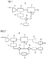
- Engine 10 comprises a combustion unit 12 configured to combust fuel to generate a mechanical output.
- Engine 10 may be a reciprocating engine or a gas turbine which may include features not shown, such as further air system components, further cooling systems, peripheries, drivetrain components, etc. Additionally, engine 10 may be used to power any machine or other device, including, but not limited to, locomotive applications, on-highway trucks or vehicles, off-highway trucks or machines, earth moving equipment, generators, planes, aerospace applications, marine applications, offshore applications, pumps, stationary equipment, or other engine powered applications.
- Engine 10 may be of any size, and, in embodiments in which engine 10 is embodied as reciprocating engine, engine 10 may have any number of cylinders, and in any configuration (for example, "V," in-line, radial, etc.). Additionally, engine 10 may be powered with any fuel including, but not limited to, diesel, heavy fuel oil, gasoline, and/or gaseous fuels.
- Engine 10 is a combustion engine which may be either an internal combustion engine or an external combustion engine.
- engine 10 may be a reciprocating internal combustion engine configured to be operated with a gaseous fuel.
- combustion unit 12 may either comprise a plurality of cylinder units with pistons reciprocating therein, or a gas turbine combustor fluidly connected upstream of a plurality of turbine blades.
- Combustion unit 12 is configured to receive a stream of charge air and fuel, combust the same, and exhaust a stream of exhaust gas.
- a compressor 14 is fluidly connected to a first cooler 16 which in turn is fluidly interconnected between compressor 14 and combustion unit 12. Additionally, a further compressor (not shown) may be provided upstream of compressor 14.
- First cooler 16 is configured as a gas cooler which is capable of cooling a passing gas such that, possibly as a side effect, water condenses from the gas.
- first cooler 16 may be configured as a charge air cooler, or may be configured as a mixture cooler for cooling a mixture of charge air and gaseous fuel to be supplied to combustion unit 12.
- first cooler 16 may be an intercooler fluidly interconnected between two compressors.
- first cooler 16 may be any cooler upstream of a gas turbine combustor, for example, a pre cooler upstream of a gas turbine compressor, any intercooler fluidly interconnected between two compressor steps, or a cooler fluidly connected downstream of the gas turbine compressor.
- a first water collector 18 is fluidly connected to first cooler 16 to collect condensing water originating from first cooler 16.
- First water collector 18 may be integrally formed with first cooler 16 or may be separately provided.
- a first pump 20 is fluidly interconnected between a water outlet of first water collector 18 and at least one water injector 22 configured to inject (spray) water in any water injection application for combustion engines.
- Direct water injectors are configured to directly inject water into combustion unit 12 which is either defined by cylinder units of a reciprocating engine, or defined by the gas turbine combustor of a gas turbine.
- indirect water injectors are configured to inject water upstream of combustion unit 12, for example, into an inlet of a gas turbine compressor, into a diffuser upstream of the gas turbine combustor, or into an air inlet (manifold) of a reciprocating engine. Operation of first pump 20 is controlled by a control unit 24 connected thereto via a control connection (indicated by a dashed dotted line in Fig. 1 ).
- FIG. 2 an engine 10' is shown with additional components compared to engine 10 of Fig. 1 .
- Engine 10' comprises an exhaust gas turbine 26 fluidly connected downstream of combustion unit 12, and a second cooler 28 fluidly connected downstream of exhaust gas turbine 26.
- a separate exhaust gas turbine 26 may be not provided as the hot exhaust gas originating from the gas turbine combustor is already expanded in the turbine blades of the gas turbine.
- second cooler 28 is configured as a gas cooler which is capable of cooling passing exhaust gas such that, possibly as a side effect, water condenses from the exhaust gas.
- the condensed water is collected by a second water collector 30 fluidly connected downstream of second cooler 28.
- Second water collector 30 may be integrally formed with second cooler 28 or may be separately provided.
- exhaust gas turbine 26 and second cooler 28 may be part of an exhaust gas recirculation (EGR) system.
- EGR exhaust gas recirculation
- a purification device 32 may be provided downstream of second water collector 30 to purify the condensed water.
- purification device 32 may be also fluidly connected to first water collector 18 to purify water therefrom, for example, in applications in which condensing water from first water collector 18 may be not already distilled due to, for example, polluted charge air.
- a second pump 34 is fluidly interconnected between the at least one water injector 22 and between a water outlet of second water collector 30.
- a single pump may be provided which functions as both first pump 20 and second pump 34. Operation of both pumps 20 and 34 may be controlled by control unit 24 via a control connection (indicated by a dashed dotted line in Fig. 2 ).
- a first water cooler may be provided downstream of first water collector 18, and/or a second water cooler (not shown) may be provided downstream of second water collector 30.
- no water cooler may be provided, or a common water cooler (not shown) may be provided downstream of both a water outlet of first water collector 18 and a water outlet of second water collector 30.
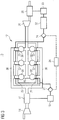
- Fig. 3 shows an internal combustion engine (also referred with reference numeral 10) configured as a reciprocating engine (piston engine) and configured to operate with gaseous fuels.
- Combustion unit 12 of reciprocating gaseous fuel engine 10 comprises an air inlet 36, a plurality of cylinder units 38, and an exhaust manifold 40, all being fluidly connected in series.
- Air inlet 36 is fluidly connected downstream of first cooler 16 which is embodied as a mixture cooler for cooling a mixture of gaseous fuel and charge air originating from compressor 14.
- Each cylinder unit 38 includes one of a plurality of water injectors 22 configured to directly inject water into the combustion chamber of the respective cylinder unit 38.
- Exhaust gas manifold 40 is fluidly connected upstream of exhaust gas turbine 26.
- engine 10 is exemplary described in connection with reciprocating gaseous fuel engine 10 depicted in Fig. 3 .
- One skilled in the art will appreciate that some of the following features and specifics may be not applicable on other engine types, whereas further features and specifics may be applicable on those other engine types which are not described in the following in connection with reciprocating gaseous fuel engine 10.
- compressor 14 pressurizes a mixture of charge air and gaseous fuel to a preset level, for example, up to 5 bar. Thereby, a temperature of the mixture increases.
- the mixture is cooled in first cooler 16, for example, down to a temperature of 50°C, which may lead to water condensation.
- first cooler 16 for example, down to a temperature of 50°C, which may lead to water condensation.
- the amount of water condensation particularly dependents on the humidity of the charge air and the charging pressure.
- Said condensing water is collected by first water collector 18, and supplied to water injectors 22 via first pump 20.
- Water injectors 22 inject water directly into the combustion chambers of cylinder units 38 during operation of internal combustion engine 10.
- exhaust gas After combustion, exhaust gas is expanded in exhaust gas turbine 26 and subsequently cooled in second cooler 28 and, thereby, condenses water from the exhaust gas.
- the condensed water is collected by second cooler 28 and supplied to water injectors 22 via second pump 34.
- a purification device 32 may be provided downstream of second water collector 30 to purify the condensed water prior injection via water injectors 22.
- control unit 24 which controls pumps 20 and 34.
- control unit 24 may directly control operation of water injectors 22.
- a redundant water supply system for supplying water to water injectors 22 may be provided by providing two water collectors 18 and 30.
- the redundant system may be either operated in that always both water collectors 18 and 30 are used to provide water to water injectors 22, or in that control unit 24 activates second pump 34 if the first pump 20 delivers a water amount below a preset water threshold. That may be, for example, the case if the charge air has a relatively low humidity, for example, below 30 %. Naturally, the condensing water amount further strongly depends on the environmental air temperature and the charging pressure as well as the cooling capability of first cooler 16.
- Said method for controlling engine 10 which is configured to apply water injection, comprises cooling charge air. Thereby, water condenses. Additionally to cool charge air, a gaseous fuel already mixed with the charge air prior cooling may be also cooled. This may be, for example, the case for gas turbines and reciprocating gaseous fuel engines.
- the condensed water is collected and provided for water injection in engine 10. Specifically, the condensed water may be supplied to or upstream of a combustion zone of engine 10.
- the combustion zone may be formed by an internal or external combustor, whereas in the case of a reciprocating engine, the combustion zone may be formed by combustion chambers of cylinder units 38.
- upstream of a combustion zone may refer to a compressor inlet in case of a gas turbine, or may refer to an air inlet (manifold) in case of a reciprocating engine.
- the charge air and the mixture of charge air and gaseous fuel may be pressurised via a compressor, respectively. Thereby, a temperature of the charge air or the mixture of charge air and gaseous fuel increases.
- exhaust is generated in the combustion zone(s) due to combustion of a fuel together with charge air.
- the exhaust gas may be cooled down by an exhaust gas cooler. Thereby, water may condense from the exhaust gas. The condensing water may be collected and supplied to or upstream of the combustion zone.
- the collected water may be additionally cooled prior injection to increase the cooling effect of the water injection.
- the temperature of condensed water from the exhaust gas may be almost 100°C before cooling, and about 50°C after cooling.
- the collected water may be purified before being injected.
- water injectors 22 may require distilled water for injection such that the collected water if not already being pure, may have to be purified by a purification device if one tries to maintain a long service life of water injectors 22.
- Water may be supplied to water injectors 22 from condensed water originating from the charge air, the mixture of charge air and gaseous fuel, and/or the exhaust gas.
- an amount of condensed water from the charge air, or the mixture of charge air and gaseous fuel may be determined, the determined condensed water amount may be compared with a preset water threshold, and the collected condensed water from the exhaust gas may be only supplied to the combustion zone if the determined condensed water amount from the charge air or the mixture is below the preset water threshold. This may ensure, that even in environments with very low humidity, enough water may be available for water injection.
- Determining a condensed water amount may be done directly by measuring the condensing water amount, or may be done indirectly, for example, by measuring an air humidity of the environment which constitutes the source for the charge air.
- the above described system may provide a rich water source formed by first water collector 18 and optionally second water collector 30 for providing water for water injection.
- a separate water tank including water may be not longer required for water injection. This may be particularly of interest for large combustion engines used, for example, in marine ships, offshore applications, and power stations.
- a redundant system may be provided which is capable to provide water even if the air humidity of the charge air may be too low for condensing enough water required for water injection.
Landscapes
- Engineering & Computer Science (AREA)
- Chemical & Material Sciences (AREA)
- Combustion & Propulsion (AREA)
- Mechanical Engineering (AREA)
- General Engineering & Computer Science (AREA)
- Water Supply & Treatment (AREA)
- General Chemical & Material Sciences (AREA)
- Oil, Petroleum & Natural Gas (AREA)
- Chemical Kinetics & Catalysis (AREA)
- Health & Medical Sciences (AREA)
- Public Health (AREA)
- Physics & Mathematics (AREA)
- Thermal Sciences (AREA)
- Output Control And Ontrol Of Special Type Engine (AREA)
- Engine Equipment That Uses Special Cycles (AREA)
- Exhaust-Gas Circulating Devices (AREA)
Claims (12)
- Gaskraftstoff-Kolbenverbrennungskraftmaschine (10) mit:einer Verbrennungseinheit (12), die dazu ausgebildet ist, eine Ladeluft-Gaskraftstoff-Strömung aufzunehmen,mindestens einem Wasserinjektor (22), der dazu ausgebildet ist, Wasser in die oder stromaufwärts von der Verbrennungseinheit (12) einzuspritzen,einem ersten Kühler (16), der in Fluidverbindung stromaufwärts von der Verbrennungseinheit (12) vorgesehen und dazu ausgebildet ist, ein Ladeluft-Gaskraftstoff-Gemisch zu kühlen, undeinem ersten Wassersammler (18), der in Fluidverbindung zwischen dem ersten Kühler (16) und dem mindestens einem Wasserinjektor (22) vorgesehen ist, wobei der erste Wassersammler (18) dazu ausgebildet ist, kondensiertes Wasser zu sammeln und das kondensierte Wasser zu dem mindestens einen Wasserinjektor (22) zu leiten.
- Gaskraftstoff-Kolbenverbrennungskraftmaschine (10) nach Anspruch 1, ferner mit
mehreren Zylindereinheiten (38), und
einem Lufteinlass (36), der in Fluidverbindung stromaufwärts von den mehreren Zylindereinheiten (38) vorgesehen ist,
wobei jede Zylindereinheit (38) einen Wasserinjektor (22) aufweist, der dazu ausgebildet ist, Wasser in die Zylindereinheit (38) einzuspritzen und/oder mindestens ein Wasserinjektor (22) dazu ausgebildet ist, Wasser in den Lufteinlass (36) einzuspritzen. - Gaskraftstoff-Kolbenverbrennungskraftmaschine (10) nach einem der vorherigen Ansprüche, mit mindestens einem von:einer ersten Pumpe (20), die in Fluidverbindung zwischen dem ersten Wassersammler (18) und dem mindestens einen Wasserinjektor (22) vorgesehen ist, und/odermindestens einem Verdichter (14), der in Fluidverbindung stromaufwärts von dem ersten Kühler (16) vorgesehen ist.
- Gaskraftstoff-Kolbenverbrennungskraftmaschine (10) nach einem der vorherigen Ansprüche, ferner aufweisend:einen zweiten Kühler (28), der in Fluidverbindung stromabwärts von der Verbrennungseinheit (12) vorgesehen ist, undeinen zweiten Wassersammler (30), der in Fluidverbindung zwischen dem zweiten Kühler (28) und dem mindestens einen Wasserinjektor (22) vorgesehen ist, wobei der zweite Wassersammler (30) dazu ausgebildet ist, kondensiertes Wasser zu sammeln und das kondensierte Wasser zu dem mindestens einen Wasserinjektor (22) zu leiten.
- Gaskraftstoff-Kolbenverbrennungskraftmaschine (10) nach Anspruch 4,
wobei die erste Pumpe (20) in Fluidverbindung stromabwärts von dem zweiten Wasserkollektor (30) vorgesehen ist, und/oder
wobei die Verbrennungskraftmaschine ferner eine zweite Pumpe (34) aufweist, die in Fluidverbindung zwischen dem zweiten Wassersammler (30) und dem mindestens einen Wasserinjektor (22) vorgesehen ist. - Gaskraftstoff-Kolbenverbrennungskraftmaschine (10) nach einem der vorherigen Ansprüche, ferner aufweisend:eine Reinigungsvorrichtung (32), die in Fluidverbindung stromabwärts von dem mindestens einen Wasserinjektor (22) vorgesehen ist, und/odereinen Wasserkühler, der in Fluidverbindung stromabwärts von dem mindestens einen Wasserinjektor (22) vorgesehen ist.
- Gaskraftstoff-Kolbenverbrennungskraftmaschine (10) nach einem der Ansprüche 4 bis 6, ferner aufweisend eine Steuereinheit (24), die dazu ausgebildet ist, die erste Pumpe (20) und die zweite Pumpe (34) zu steuern, wobei die Steuereinheit (24) die zweite Pumpe (34) einschaltet, wenn die erste Pumpe (20) eine Wassermenge fördert, die unter einem vorgegebenen Wasserschwellwert ist.
- Verfahren zum Steuern einer Gaskraftstoff-Kolbenverbrennungskraftmaschine (10), wobei das Verfahren aufweist:Kühlen eines Ladeluft-Gaskraftstoff-Gemischs und dadurch Kondensieren von Wasser,Sammeln des kondensierten Wassers, undZuführen des gesammelten kondensierten Wassers zur Wassereinspritzung in eine oder stromaufwärts von einer Verbrennungszone der Gaskraftstoff-Kolbenverbrennungskraftmäschine (10).
- Verfahren nach Anspruch 8, ferner aufweisend:Verdichten der Ladeluft vor dem Kühlen der Ladeluft, oderVerdichten des Ladeluft-Gaskraftstoff-Gemischs vor dem Kühlen des Gemischs.
- Verfahren nach Anspruch 8 oder 9, ferner aufweisend:Verbrennen eines Ladeluft-Kraftstoff-Gemischs dadurch Erzeugen von Abgas,Kühlen des Abgases und dadurch Kondensieren von Wasser,Sammeln des kondensierten Wassers aus dem Abgas, undLeiten des gesammelten kondensieren Wassers aus dem Abgas zur Wassereinspritzung.
- Verfahren nach einem der Ansprüche 8 bis 10, ferner aufweisend:Kühlen des gesammelten kondensierten Wassers, und/oderReinigen des gesammelten kondensierten Wassers.
- Verfahren nach Anspruch 10 oder 11, ferner aufweisend:Bestimmen einer Menge von kondensiertem Wasser aus der Ladeluft oder dem Ladeluft-Gaskraftstoff-Gemisch,Vergleichen der bestimmten kondensierten Wassermenge mit einem vorgegebenen Wasserschwellwert, undLeiten des gesammelten kondensierten Wassers aus dem Abgas zur Wassereinspritzung nur dann, wenn die bestimmte kondensierte Wassermenge unter dem vorgegebenen Wasserschwellwert ist.
Priority Applications (2)
| Application Number | Priority Date | Filing Date | Title |
|---|---|---|---|
| EP13168274.2A EP2803836B1 (de) | 2013-05-17 | 2013-05-17 | Wassereinspritzung in Verbrennungsmotoren |
| CN201420251777.0U CN203847276U (zh) | 2013-05-17 | 2014-05-16 | 燃烧式发动机 |
Applications Claiming Priority (1)
| Application Number | Priority Date | Filing Date | Title |
|---|---|---|---|
| EP13168274.2A EP2803836B1 (de) | 2013-05-17 | 2013-05-17 | Wassereinspritzung in Verbrennungsmotoren |
Publications (2)
| Publication Number | Publication Date |
|---|---|
| EP2803836A1 EP2803836A1 (de) | 2014-11-19 |
| EP2803836B1 true EP2803836B1 (de) | 2016-05-25 |
Family
ID=48484989
Family Applications (1)
| Application Number | Title | Priority Date | Filing Date |
|---|---|---|---|
| EP13168274.2A Active EP2803836B1 (de) | 2013-05-17 | 2013-05-17 | Wassereinspritzung in Verbrennungsmotoren |
Country Status (2)
| Country | Link |
|---|---|
| EP (1) | EP2803836B1 (de) |
| CN (1) | CN203847276U (de) |
Cited By (2)
| Publication number | Priority date | Publication date | Assignee | Title |
|---|---|---|---|---|
| US10895224B1 (en) | 2019-07-01 | 2021-01-19 | Caterpillar Inc. | Exhaust system for internal combustion engine and condensate disposal strategy for same |
| KR102214581B1 (ko) * | 2019-11-20 | 2021-02-10 | 주식회사 현대케피코 | 물 분사 차량의 물 보충 시스템 및 물 보충 시스템의 제어 방법 |
Families Citing this family (2)
| Publication number | Priority date | Publication date | Assignee | Title |
|---|---|---|---|---|
| US9932921B2 (en) | 2015-10-26 | 2018-04-03 | Ford Global Technologies, Llc | Method for utilizing condensate to improve engine efficiency |
| GB2614037A (en) * | 2021-11-03 | 2023-06-28 | Siemens Energy Global Gmbh & Co Kg | Gas turbine arrangement |
Citations (1)
| Publication number | Priority date | Publication date | Assignee | Title |
|---|---|---|---|---|
| WO2010128127A2 (de) * | 2009-05-07 | 2010-11-11 | Avl List Gmbh | Verfahren zum starten einer mit brenngas betriebenen brennkraftmaschine |
Family Cites Families (8)
| Publication number | Priority date | Publication date | Assignee | Title |
|---|---|---|---|---|
| AU8798782A (en) * | 1981-09-16 | 1983-03-24 | Bbc Brown Boveri A.G | Reducing nox in gas turbine exhaust |
| DE102006054227A1 (de) * | 2006-11-15 | 2008-05-21 | Behr Gmbh & Co. Kg | Verfahren zur Verringerung des Schadstoffausstoßes einer Brennkraftmaschine, Vorrichtung zur Durchführung des Verfahrens und Abgasrückführsystem |
| SE530953C2 (sv) * | 2007-10-03 | 2008-11-04 | Scania Cv Abp | Anordning för avledning av kondensat |
| EP2161438B1 (de) * | 2008-09-03 | 2015-01-21 | Behr GmbH & Co. KG | System zur Rückführung von Abgas einer Verbrennungskraftmaschine und Verfahren zur Rückführung von Abgas einer Verbrennungskraftmaschine |
| FR2936023B1 (fr) * | 2008-09-12 | 2015-06-26 | Valeo Systemes Thermiques | Systeme d'evacuation de produits de condensation formes dans un circuit d'alimentation en air d'un moteur d'un vehicule automobile et procede de gestion d'un tel systeme |
| FR2957980A1 (fr) * | 2010-03-24 | 2011-09-30 | Renault Sas | Circuit d'admission d'un moteur a combustion interne |
| US8371278B2 (en) | 2010-04-23 | 2013-02-12 | Deere & Company | High flow EGR system |
| JP5211115B2 (ja) * | 2010-06-28 | 2013-06-12 | 三菱重工業株式会社 | ガスエンジンの給気冷却器のドレン装置 |
-
2013
- 2013-05-17 EP EP13168274.2A patent/EP2803836B1/de active Active
-
2014
- 2014-05-16 CN CN201420251777.0U patent/CN203847276U/zh not_active Expired - Fee Related
Patent Citations (1)
| Publication number | Priority date | Publication date | Assignee | Title |
|---|---|---|---|---|
| WO2010128127A2 (de) * | 2009-05-07 | 2010-11-11 | Avl List Gmbh | Verfahren zum starten einer mit brenngas betriebenen brennkraftmaschine |
Cited By (2)
| Publication number | Priority date | Publication date | Assignee | Title |
|---|---|---|---|---|
| US10895224B1 (en) | 2019-07-01 | 2021-01-19 | Caterpillar Inc. | Exhaust system for internal combustion engine and condensate disposal strategy for same |
| KR102214581B1 (ko) * | 2019-11-20 | 2021-02-10 | 주식회사 현대케피코 | 물 분사 차량의 물 보충 시스템 및 물 보충 시스템의 제어 방법 |
Also Published As
| Publication number | Publication date |
|---|---|
| CN203847276U (zh) | 2014-09-24 |
| EP2803836A1 (de) | 2014-11-19 |
Similar Documents
| Publication | Publication Date | Title |
|---|---|---|
| CN105526021B (zh) | 发动机中的供体和非供体汽缸之间的不同的燃料供给 | |
| US5937799A (en) | Cylinder water injection engine | |
| US8371278B2 (en) | High flow EGR system | |
| US9243589B2 (en) | High-enthalpy fluid injection | |
| RU2622457C1 (ru) | Двигатель внутреннего сгорания на основе изотермического сжатия, способ его работы и его управления | |
| EP2803836B1 (de) | Wassereinspritzung in Verbrennungsmotoren | |
| US10920658B2 (en) | Waste heat powered exhaust pump | |
| JP2012172647A (ja) | ターボ過給機を備えたエンジンの排熱回収システム | |
| US9631580B2 (en) | High-enthalpy fluid injection integrated with glow plug | |
| CN114439608A (zh) | 水循环缸内喷水氢气内燃机及汽车 | |
| CN103003532B (zh) | 包括热回收回路的发动机设备 | |
| US20150377108A1 (en) | Dual fuel engine system | |
| CN103069133A (zh) | 具有液态燃料和气态燃料的内燃机 | |
| US20130104542A1 (en) | Exhaust gas recirculation in a reciprocating engine having a multiple-stroke configuration | |
| US20160097350A1 (en) | High-enthalpy fluid injection integrated with spark plug | |
| US20170051634A1 (en) | Vehicle heat recovery system | |
| IL181497A (en) | Injection device and procedure for feeding diesel engines with hydro-alcoholic blends | |
| US20260002497A1 (en) | Internal combustion engine system | |
| US20120272647A1 (en) | Exhaust heat reuse and transferring device | |
| GB2635344A (en) | Cooling system for a vehicle | |
| Park et al. | NOx Reduction of a Medium Speed Diesel Engine Using a Charge Air Moisturizer System | |
| KR20240137154A (ko) | 배기가스의 질소산화물 저감장치 및 이를 포함하는 엔진 시스템 | |
| RU169838U1 (ru) | Система питания автотракторного дизеля | |
| KR101270966B1 (ko) | 내연기관 연비향상 시스템 | |
| WO2025224038A1 (en) | Apparatus and method for improving efficiency of propulsion systems |
Legal Events
| Date | Code | Title | Description |
|---|---|---|---|
| PUAI | Public reference made under article 153(3) epc to a published international application that has entered the european phase |
Free format text: ORIGINAL CODE: 0009012 |
|
| 17P | Request for examination filed |
Effective date: 20130517 |
|
| AK | Designated contracting states |
Kind code of ref document: A1 Designated state(s): AL AT BE BG CH CY CZ DE DK EE ES FI FR GB GR HR HU IE IS IT LI LT LU LV MC MK MT NL NO PL PT RO RS SE SI SK SM TR |
|
| AX | Request for extension of the european patent |
Extension state: BA ME |
|
| R17P | Request for examination filed (corrected) |
Effective date: 20150421 |
|
| RBV | Designated contracting states (corrected) |
Designated state(s): AL AT BE BG CH CY CZ DE DK EE ES FI FR GB GR HR HU IE IS IT LI LT LU LV MC MK MT NL NO PL PT RO RS SE SI SK SM TR |
|
| RIC1 | Information provided on ipc code assigned before grant |
Ipc: F02M 25/022 20060101ALI20151126BHEP Ipc: F02B 29/04 20060101AFI20151126BHEP Ipc: F02C 3/30 20060101ALI20151126BHEP Ipc: F02M 35/08 20060101ALI20151126BHEP |
|
| GRAP | Despatch of communication of intention to grant a patent |
Free format text: ORIGINAL CODE: EPIDOSNIGR1 |
|
| INTG | Intention to grant announced |
Effective date: 20160104 |
|
| GRAS | Grant fee paid |
Free format text: ORIGINAL CODE: EPIDOSNIGR3 |
|
| GRAA | (expected) grant |
Free format text: ORIGINAL CODE: 0009210 |
|
| AK | Designated contracting states |
Kind code of ref document: B1 Designated state(s): AL AT BE BG CH CY CZ DE DK EE ES FI FR GB GR HR HU IE IS IT LI LT LU LV MC MK MT NL NO PL PT RO RS SE SI SK SM TR |
|
| REG | Reference to a national code |
Ref country code: GB Ref legal event code: FG4D |
|
| REG | Reference to a national code |
Ref country code: CH Ref legal event code: EP |
|
| REG | Reference to a national code |
Ref country code: IE Ref legal event code: FG4D Ref country code: AT Ref legal event code: REF Ref document number: 802530 Country of ref document: AT Kind code of ref document: T Effective date: 20160615 |
|
| REG | Reference to a national code |
Ref country code: DE Ref legal event code: R096 Ref document number: 602013007802 Country of ref document: DE |
|
| REG | Reference to a national code |
Ref country code: LT Ref legal event code: MG4D |
|
| REG | Reference to a national code |
Ref country code: NL Ref legal event code: MP Effective date: 20160525 |
|
| PG25 | Lapsed in a contracting state [announced via postgrant information from national office to epo] |
Ref country code: LT Free format text: LAPSE BECAUSE OF FAILURE TO SUBMIT A TRANSLATION OF THE DESCRIPTION OR TO PAY THE FEE WITHIN THE PRESCRIBED TIME-LIMIT Effective date: 20160525 Ref country code: NO Free format text: LAPSE BECAUSE OF FAILURE TO SUBMIT A TRANSLATION OF THE DESCRIPTION OR TO PAY THE FEE WITHIN THE PRESCRIBED TIME-LIMIT Effective date: 20160825 Ref country code: FI Free format text: LAPSE BECAUSE OF FAILURE TO SUBMIT A TRANSLATION OF THE DESCRIPTION OR TO PAY THE FEE WITHIN THE PRESCRIBED TIME-LIMIT Effective date: 20160525 Ref country code: NL Free format text: LAPSE BECAUSE OF FAILURE TO SUBMIT A TRANSLATION OF THE DESCRIPTION OR TO PAY THE FEE WITHIN THE PRESCRIBED TIME-LIMIT Effective date: 20160525 |
|
| REG | Reference to a national code |
Ref country code: AT Ref legal event code: MK05 Ref document number: 802530 Country of ref document: AT Kind code of ref document: T Effective date: 20160525 |
|
| PG25 | Lapsed in a contracting state [announced via postgrant information from national office to epo] |
Ref country code: LV Free format text: LAPSE BECAUSE OF FAILURE TO SUBMIT A TRANSLATION OF THE DESCRIPTION OR TO PAY THE FEE WITHIN THE PRESCRIBED TIME-LIMIT Effective date: 20160525 Ref country code: GR Free format text: LAPSE BECAUSE OF FAILURE TO SUBMIT A TRANSLATION OF THE DESCRIPTION OR TO PAY THE FEE WITHIN THE PRESCRIBED TIME-LIMIT Effective date: 20160826 Ref country code: PT Free format text: LAPSE BECAUSE OF FAILURE TO SUBMIT A TRANSLATION OF THE DESCRIPTION OR TO PAY THE FEE WITHIN THE PRESCRIBED TIME-LIMIT Effective date: 20160926 Ref country code: SE Free format text: LAPSE BECAUSE OF FAILURE TO SUBMIT A TRANSLATION OF THE DESCRIPTION OR TO PAY THE FEE WITHIN THE PRESCRIBED TIME-LIMIT Effective date: 20160525 Ref country code: RS Free format text: LAPSE BECAUSE OF FAILURE TO SUBMIT A TRANSLATION OF THE DESCRIPTION OR TO PAY THE FEE WITHIN THE PRESCRIBED TIME-LIMIT Effective date: 20160525 |
|
| PG25 | Lapsed in a contracting state [announced via postgrant information from national office to epo] |
Ref country code: IT Free format text: LAPSE BECAUSE OF FAILURE TO SUBMIT A TRANSLATION OF THE DESCRIPTION OR TO PAY THE FEE WITHIN THE PRESCRIBED TIME-LIMIT Effective date: 20160525 |
|
| PG25 | Lapsed in a contracting state [announced via postgrant information from national office to epo] |
Ref country code: RO Free format text: LAPSE BECAUSE OF FAILURE TO SUBMIT A TRANSLATION OF THE DESCRIPTION OR TO PAY THE FEE WITHIN THE PRESCRIBED TIME-LIMIT Effective date: 20160525 Ref country code: EE Free format text: LAPSE BECAUSE OF FAILURE TO SUBMIT A TRANSLATION OF THE DESCRIPTION OR TO PAY THE FEE WITHIN THE PRESCRIBED TIME-LIMIT Effective date: 20160525 Ref country code: CZ Free format text: LAPSE BECAUSE OF FAILURE TO SUBMIT A TRANSLATION OF THE DESCRIPTION OR TO PAY THE FEE WITHIN THE PRESCRIBED TIME-LIMIT Effective date: 20160525 Ref country code: SK Free format text: LAPSE BECAUSE OF FAILURE TO SUBMIT A TRANSLATION OF THE DESCRIPTION OR TO PAY THE FEE WITHIN THE PRESCRIBED TIME-LIMIT Effective date: 20160525 Ref country code: DK Free format text: LAPSE BECAUSE OF FAILURE TO SUBMIT A TRANSLATION OF THE DESCRIPTION OR TO PAY THE FEE WITHIN THE PRESCRIBED TIME-LIMIT Effective date: 20160525 |
|
| PG25 | Lapsed in a contracting state [announced via postgrant information from national office to epo] |
Ref country code: BE Free format text: LAPSE BECAUSE OF FAILURE TO SUBMIT A TRANSLATION OF THE DESCRIPTION OR TO PAY THE FEE WITHIN THE PRESCRIBED TIME-LIMIT Effective date: 20160525 Ref country code: SM Free format text: LAPSE BECAUSE OF FAILURE TO SUBMIT A TRANSLATION OF THE DESCRIPTION OR TO PAY THE FEE WITHIN THE PRESCRIBED TIME-LIMIT Effective date: 20160525 Ref country code: PL Free format text: LAPSE BECAUSE OF FAILURE TO SUBMIT A TRANSLATION OF THE DESCRIPTION OR TO PAY THE FEE WITHIN THE PRESCRIBED TIME-LIMIT Effective date: 20160525 Ref country code: AT Free format text: LAPSE BECAUSE OF FAILURE TO SUBMIT A TRANSLATION OF THE DESCRIPTION OR TO PAY THE FEE WITHIN THE PRESCRIBED TIME-LIMIT Effective date: 20160525 |
|
| REG | Reference to a national code |
Ref country code: DE Ref legal event code: R097 Ref document number: 602013007802 Country of ref document: DE |
|
| PLBE | No opposition filed within time limit |
Free format text: ORIGINAL CODE: 0009261 |
|
| STAA | Information on the status of an ep patent application or granted ep patent |
Free format text: STATUS: NO OPPOSITION FILED WITHIN TIME LIMIT |
|
| 26N | No opposition filed |
Effective date: 20170228 |
|
| PG25 | Lapsed in a contracting state [announced via postgrant information from national office to epo] |
Ref country code: SI Free format text: LAPSE BECAUSE OF FAILURE TO SUBMIT A TRANSLATION OF THE DESCRIPTION OR TO PAY THE FEE WITHIN THE PRESCRIBED TIME-LIMIT Effective date: 20160525 |
|
| PG25 | Lapsed in a contracting state [announced via postgrant information from national office to epo] |
Ref country code: LU Free format text: LAPSE BECAUSE OF NON-PAYMENT OF DUE FEES Effective date: 20170531 |
|
| REG | Reference to a national code |
Ref country code: CH Ref legal event code: PL |
|
| GBPC | Gb: european patent ceased through non-payment of renewal fee |
Effective date: 20170517 |
|
| PG25 | Lapsed in a contracting state [announced via postgrant information from national office to epo] |
Ref country code: MC Free format text: LAPSE BECAUSE OF FAILURE TO SUBMIT A TRANSLATION OF THE DESCRIPTION OR TO PAY THE FEE WITHIN THE PRESCRIBED TIME-LIMIT Effective date: 20160525 |
|
| REG | Reference to a national code |
Ref country code: IE Ref legal event code: MM4A |
|
| PG25 | Lapsed in a contracting state [announced via postgrant information from national office to epo] |
Ref country code: LI Free format text: LAPSE BECAUSE OF NON-PAYMENT OF DUE FEES Effective date: 20170531 Ref country code: CH Free format text: LAPSE BECAUSE OF NON-PAYMENT OF DUE FEES Effective date: 20170531 |
|
| REG | Reference to a national code |
Ref country code: FR Ref legal event code: ST Effective date: 20180131 |
|
| PG25 | Lapsed in a contracting state [announced via postgrant information from national office to epo] |
Ref country code: LU Free format text: LAPSE BECAUSE OF NON-PAYMENT OF DUE FEES Effective date: 20170517 |
|
| PG25 | Lapsed in a contracting state [announced via postgrant information from national office to epo] |
Ref country code: GB Free format text: LAPSE BECAUSE OF NON-PAYMENT OF DUE FEES Effective date: 20170517 Ref country code: IE Free format text: LAPSE BECAUSE OF NON-PAYMENT OF DUE FEES Effective date: 20170517 |
|
| PG25 | Lapsed in a contracting state [announced via postgrant information from national office to epo] |
Ref country code: FR Free format text: LAPSE BECAUSE OF NON-PAYMENT OF DUE FEES Effective date: 20170531 |
|
| PG25 | Lapsed in a contracting state [announced via postgrant information from national office to epo] |
Ref country code: MT Free format text: LAPSE BECAUSE OF NON-PAYMENT OF DUE FEES Effective date: 20170517 |
|
| PG25 | Lapsed in a contracting state [announced via postgrant information from national office to epo] |
Ref country code: AL Free format text: LAPSE BECAUSE OF FAILURE TO SUBMIT A TRANSLATION OF THE DESCRIPTION OR TO PAY THE FEE WITHIN THE PRESCRIBED TIME-LIMIT Effective date: 20160525 |
|
| PG25 | Lapsed in a contracting state [announced via postgrant information from national office to epo] |
Ref country code: HU Free format text: LAPSE BECAUSE OF FAILURE TO SUBMIT A TRANSLATION OF THE DESCRIPTION OR TO PAY THE FEE WITHIN THE PRESCRIBED TIME-LIMIT; INVALID AB INITIO Effective date: 20130517 |
|
| PG25 | Lapsed in a contracting state [announced via postgrant information from national office to epo] |
Ref country code: BG Free format text: LAPSE BECAUSE OF FAILURE TO SUBMIT A TRANSLATION OF THE DESCRIPTION OR TO PAY THE FEE WITHIN THE PRESCRIBED TIME-LIMIT Effective date: 20160525 |
|
| PG25 | Lapsed in a contracting state [announced via postgrant information from national office to epo] |
Ref country code: ES Free format text: LAPSE BECAUSE OF FAILURE TO SUBMIT A TRANSLATION OF THE DESCRIPTION OR TO PAY THE FEE WITHIN THE PRESCRIBED TIME-LIMIT Effective date: 20160525 Ref country code: CY Free format text: LAPSE BECAUSE OF FAILURE TO SUBMIT A TRANSLATION OF THE DESCRIPTION OR TO PAY THE FEE WITHIN THE PRESCRIBED TIME-LIMIT Effective date: 20160525 |
|
| PG25 | Lapsed in a contracting state [announced via postgrant information from national office to epo] |
Ref country code: MK Free format text: LAPSE BECAUSE OF FAILURE TO SUBMIT A TRANSLATION OF THE DESCRIPTION OR TO PAY THE FEE WITHIN THE PRESCRIBED TIME-LIMIT Effective date: 20160525 |
|
| PG25 | Lapsed in a contracting state [announced via postgrant information from national office to epo] |
Ref country code: TR Free format text: LAPSE BECAUSE OF FAILURE TO SUBMIT A TRANSLATION OF THE DESCRIPTION OR TO PAY THE FEE WITHIN THE PRESCRIBED TIME-LIMIT Effective date: 20160525 |
|
| PG25 | Lapsed in a contracting state [announced via postgrant information from national office to epo] |
Ref country code: HR Free format text: LAPSE BECAUSE OF FAILURE TO SUBMIT A TRANSLATION OF THE DESCRIPTION OR TO PAY THE FEE WITHIN THE PRESCRIBED TIME-LIMIT Effective date: 20160525 |
|
| PG25 | Lapsed in a contracting state [announced via postgrant information from national office to epo] |
Ref country code: IS Free format text: LAPSE BECAUSE OF FAILURE TO SUBMIT A TRANSLATION OF THE DESCRIPTION OR TO PAY THE FEE WITHIN THE PRESCRIBED TIME-LIMIT Effective date: 20160925 |
|
| P01 | Opt-out of the competence of the unified patent court (upc) registered |
Effective date: 20230517 |
|
| PGFP | Annual fee paid to national office [announced via postgrant information from national office to epo] |
Ref country code: DE Payment date: 20250423 Year of fee payment: 13 |