EP2803853B1 - Damping wind turbine tower oscillations using gyroscopic forces - Google Patents
Damping wind turbine tower oscillations using gyroscopic forces Download PDFInfo
- Publication number
- EP2803853B1 EP2803853B1 EP13168207.2A EP13168207A EP2803853B1 EP 2803853 B1 EP2803853 B1 EP 2803853B1 EP 13168207 A EP13168207 A EP 13168207A EP 2803853 B1 EP2803853 B1 EP 2803853B1
- Authority
- EP
- European Patent Office
- Prior art keywords
- tower
- wind turbine
- yawing
- movement
- rotor
- Prior art date
- Legal status (The legal status is an assumption and is not a legal conclusion. Google has not performed a legal analysis and makes no representation as to the accuracy of the status listed.)
- Not-in-force
Links
- 238000013016 damping Methods 0.000 title claims description 31
- 230000010355 oscillation Effects 0.000 title description 26
- 230000033001 locomotion Effects 0.000 claims description 96
- 230000003534 oscillatory effect Effects 0.000 claims description 45
- 238000000034 method Methods 0.000 claims description 25
- 230000000737 periodic effect Effects 0.000 claims description 20
- 230000000694 effects Effects 0.000 claims description 12
- 238000004590 computer program Methods 0.000 claims description 9
- 230000001133 acceleration Effects 0.000 description 8
- 230000006870 function Effects 0.000 description 4
- 238000004519 manufacturing process Methods 0.000 description 2
- 238000005259 measurement Methods 0.000 description 2
- 229910000831 Steel Inorganic materials 0.000 description 1
- 230000009286 beneficial effect Effects 0.000 description 1
- 230000001419 dependent effect Effects 0.000 description 1
- 238000010586 diagram Methods 0.000 description 1
- 230000010354 integration Effects 0.000 description 1
- 238000010248 power generation Methods 0.000 description 1
- 229920006395 saturated elastomer Polymers 0.000 description 1
- 239000010959 steel Substances 0.000 description 1
Images


Classifications
-
- F—MECHANICAL ENGINEERING; LIGHTING; HEATING; WEAPONS; BLASTING
- F03—MACHINES OR ENGINES FOR LIQUIDS; WIND, SPRING, OR WEIGHT MOTORS; PRODUCING MECHANICAL POWER OR A REACTIVE PROPULSIVE THRUST, NOT OTHERWISE PROVIDED FOR
- F03D—WIND MOTORS
- F03D7/00—Controlling wind motors
- F03D7/02—Controlling wind motors the wind motors having rotation axis substantially parallel to the air flow entering the rotor
- F03D7/0296—Controlling wind motors the wind motors having rotation axis substantially parallel to the air flow entering the rotor to prevent, counteract or reduce noise emissions
-
- F—MECHANICAL ENGINEERING; LIGHTING; HEATING; WEAPONS; BLASTING
- F03—MACHINES OR ENGINES FOR LIQUIDS; WIND, SPRING, OR WEIGHT MOTORS; PRODUCING MECHANICAL POWER OR A REACTIVE PROPULSIVE THRUST, NOT OTHERWISE PROVIDED FOR
- F03D—WIND MOTORS
- F03D7/00—Controlling wind motors
- F03D7/02—Controlling wind motors the wind motors having rotation axis substantially parallel to the air flow entering the rotor
- F03D7/0204—Controlling wind motors the wind motors having rotation axis substantially parallel to the air flow entering the rotor for orientation in relation to wind direction
-
- F—MECHANICAL ENGINEERING; LIGHTING; HEATING; WEAPONS; BLASTING
- F03—MACHINES OR ENGINES FOR LIQUIDS; WIND, SPRING, OR WEIGHT MOTORS; PRODUCING MECHANICAL POWER OR A REACTIVE PROPULSIVE THRUST, NOT OTHERWISE PROVIDED FOR
- F03D—WIND MOTORS
- F03D9/00—Adaptations of wind motors for special use; Combinations of wind motors with apparatus driven thereby; Wind motors specially adapted for installation in particular locations
- F03D9/20—Wind motors characterised by the driven apparatus
- F03D9/25—Wind motors characterised by the driven apparatus the apparatus being an electrical generator
-
- F—MECHANICAL ENGINEERING; LIGHTING; HEATING; WEAPONS; BLASTING
- F03—MACHINES OR ENGINES FOR LIQUIDS; WIND, SPRING, OR WEIGHT MOTORS; PRODUCING MECHANICAL POWER OR A REACTIVE PROPULSIVE THRUST, NOT OTHERWISE PROVIDED FOR
- F03D—WIND MOTORS
- F03D7/00—Controlling wind motors
- F03D7/02—Controlling wind motors the wind motors having rotation axis substantially parallel to the air flow entering the rotor
- F03D7/028—Controlling wind motors the wind motors having rotation axis substantially parallel to the air flow entering the rotor controlling wind motor output power
- F03D7/0292—Controlling wind motors the wind motors having rotation axis substantially parallel to the air flow entering the rotor controlling wind motor output power to reduce fatigue
-
- F—MECHANICAL ENGINEERING; LIGHTING; HEATING; WEAPONS; BLASTING
- F05—INDEXING SCHEMES RELATING TO ENGINES OR PUMPS IN VARIOUS SUBCLASSES OF CLASSES F01-F04
- F05B—INDEXING SCHEME RELATING TO WIND, SPRING, WEIGHT, INERTIA OR LIKE MOTORS, TO MACHINES OR ENGINES FOR LIQUIDS COVERED BY SUBCLASSES F03B, F03D AND F03G
- F05B2260/00—Function
- F05B2260/96—Preventing, counteracting or reducing vibration or noise
-
- F—MECHANICAL ENGINEERING; LIGHTING; HEATING; WEAPONS; BLASTING
- F05—INDEXING SCHEMES RELATING TO ENGINES OR PUMPS IN VARIOUS SUBCLASSES OF CLASSES F01-F04
- F05B—INDEXING SCHEME RELATING TO WIND, SPRING, WEIGHT, INERTIA OR LIKE MOTORS, TO MACHINES OR ENGINES FOR LIQUIDS COVERED BY SUBCLASSES F03B, F03D AND F03G
- F05B2270/00—Control
- F05B2270/10—Purpose of the control system
- F05B2270/109—Purpose of the control system to prolong engine life
- F05B2270/1095—Purpose of the control system to prolong engine life by limiting mechanical stresses
-
- F—MECHANICAL ENGINEERING; LIGHTING; HEATING; WEAPONS; BLASTING
- F05—INDEXING SCHEMES RELATING TO ENGINES OR PUMPS IN VARIOUS SUBCLASSES OF CLASSES F01-F04
- F05B—INDEXING SCHEME RELATING TO WIND, SPRING, WEIGHT, INERTIA OR LIKE MOTORS, TO MACHINES OR ENGINES FOR LIQUIDS COVERED BY SUBCLASSES F03B, F03D AND F03G
- F05B2270/00—Control
- F05B2270/30—Control parameters, e.g. input parameters
- F05B2270/332—Maximum loads or fatigue criteria
-
- Y—GENERAL TAGGING OF NEW TECHNOLOGICAL DEVELOPMENTS; GENERAL TAGGING OF CROSS-SECTIONAL TECHNOLOGIES SPANNING OVER SEVERAL SECTIONS OF THE IPC; TECHNICAL SUBJECTS COVERED BY FORMER USPC CROSS-REFERENCE ART COLLECTIONS [XRACs] AND DIGESTS
- Y02—TECHNOLOGIES OR APPLICATIONS FOR MITIGATION OR ADAPTATION AGAINST CLIMATE CHANGE
- Y02E—REDUCTION OF GREENHOUSE GAS [GHG] EMISSIONS, RELATED TO ENERGY GENERATION, TRANSMISSION OR DISTRIBUTION
- Y02E10/00—Energy generation through renewable energy sources
- Y02E10/70—Wind energy
- Y02E10/72—Wind turbines with rotation axis in wind direction
Definitions
- the present invention generally relates to the technical field of operating wind turbines. Specifically, the present invention relates to the technical field of operating a wind turbine in such a manner that fatigue loads acting on a tower of the wind turbine are minimized. In particular, the present invention relates to a method and to a control device for damping an oscillatory movement of the top of a tower of a wind turbine. Further, the present invention relates to a wind turbine comprising such a control device and to a computer program for controlling this method.
- the fatigue load a tower of a wind turbine has to withstand is often a key parameter for the structural design of a wind turbine tower. If it is possible to reduce the fatigue load acting on the wind turbine tower then the tower could be manufactured with a less amount of steel which would result in a reduced cost and in a reduced weight of the tower. Alternatively, with a reduced fatigue load acting on the same wind turbine tower the tower could have a longer life time.
- a first fatigue load results from a tower top movement in a direction being horizontal and perpendicular to the direction of the wind. These tower top oscillations may be called side-side oscillations.
- a second fatigue load results from a tower top movement in a direction along the direction of the wind. These tower top oscillations may be called fore-aft oscillations.
- EP 2146093 B1 discloses a method for damping oscillations of a tower of a wind turbine where the side-side tower fatigue load is reduced by damping the tower movement using a sinusoidal signal added to a power/torque reference signal used for controlling the operation of a wind turbine.
- the added signal will generate a sinusoidal component in the torque applied by the turbine generator which is located in the nacelle of the wind turbine.
- Figure 5 shows that e.g. a clockwise torque moves the wind turbine tower top to the right.
- a method for damping an oscillatory movement of the top of a tower of a wind turbine comprises (a) rotating a rotor being rotatably attached to a nacelle of the wind turbine with a rotational speed, and (b) yawing the nacelle of the wind turbine around an axis being aligned with the longitudinal axis of the tower with a yawing speed.
- a yawing movement being associated with yawing the nacelle is coordinated with the oscillatory movement in such a manner that a gyroscopic torque resulting (i) from rotating the rotor and (ii) from yawing the rotor damps the oscillatory movement of the top of the tower.
- the described method is based on the idea that gyroscopic forces and in particular a gyroscopic torque, which results both from rotating and from yawing the rotor having a given moment of inertia, can be used for damping or reducing oscillatory movements of the top of a tower of a wind turbine.
- oscillations of (the top of) the tower in the fore-aft direction with respect to the direction of the wind driving the wind turbine can be avoided or, in case such fore-aft oscillations have already been developed, can be damped in an easy and effective manner.
- rotor may refer to the mechanical system comprising a rotor hub and at least two rotor blades extending radially from the rotor hub.
- r is the radius vector to a point in the rigid body from the specified rotational axis
- ⁇ ( r ) is the mass density at each point r.
- the integration is evaluated over the whole volume V of the rigid body.
- the rotor blades have a spatial extension which reaches far away from the rotational axis the rotor blades represent the largest contribution to the moment of inertia J of the rotor.
- the rotor hub and a rotor shaft, which connect the rotor hub directly or indirectly (e.g. via a gear box) to an electric generator of the wind turbine represent a much smaller and typically negligible contribution to the moment of inertia J of the rotor.
- ⁇ is the vector representing the rotational move-ment of the rotor.
- the vector ⁇ is aligned with the rotational axis of the rotor.
- ⁇ y is the vector representing the yawing movement of the rotor respectively of the nacelle.
- the vector ⁇ y is aligned with the longitudinal and vertical extension of the tower.
- the vector Mg is oriented perpendicular both to ⁇ and to ⁇ y .
- the nacelle may be tilted a little bit such that ⁇ and ⁇ y are not exactly perpendicular to each other.
- the tilt angle typically 5 to 6 deg is relative small such that the assumption taken below is reasonable.
- is a function of the rotor speed direction of the rotational speed of the rotor (which is typically always the same) and the direction of the yawing speed (or yaw direction), which can be controlled. Therefore, by controlling the yaw direction one can control the direction of the gyroscopic torque
- the method further comprises (a) measuring a movement of the tower and (b) determining the oscillatory movement of the top of the tower based on the measured tower movement.
- the tower top oscillatory movement can be estimated or measured based on the oscillatory varying position of the tower top, the oscillatory speed and/or the oscillatory acceleration of the tower top. In practice, it may be easiest to measure the acceleration of the tower top and to derive from the resulting acceleration values the oscillatory tower top movement. However, measuring the tower top speed, the tower top position or the tilt angle of the tower top may also, instead or in combination, be used for determining the movement of the tower top.
- a mechanical strain and/or a mechanical load in the tower can be measured by using strain gauges.
- the signal output of such strain gauges can be used for determining the tower top oscillatory movement.
- the signal output of such strain gauges can be used for timing the yawing movement respectively the gyroscopic torque, which result in the described damping of the tower top movement.
- the oscillatory movement of the top of the tower of the wind turbine has a periodic time dependency and the sign of the oscillatory movement of changes periodically.
- the yawing movement has a periodic time dependency and the direction of yawing the rotor changes periodically such that the resulting gyroscopic torque has a periodic time dependency and the sign of the gyroscopic torque changes periodically.
- the described method can be used for damping an oscillatory movement of the tower top, which has a periodic time dependency. This may provide the advantage that the described method can be used effectively for reducing a periodic mechanical torque acting on the tower top, which periodic mechanical torque frequently occurs when the tower top exhibits fore-aft oscillations.
- the periodic time dependency of the oscillatory movement of the top of the tower is at least approximately sinusoidal and the periodic time dependency of the yawing movement and the resulting gyroscopic torque is at least approximately sinusoidal.
- yawing the nacelle of the wind turbine is carried out for aligning the rotational axis of the rotor at least approximately with an actual direction of a wind driving the wind turbine.
- the yawing activity is timely coordinated with a periodic fore-aft movement of the top of the tower.
- the described yawing movement which is coordinated with the fore-aft tower oscillations may at least in some operational conditions allow for reducing at least partially the oscillatory movement of the top of the tower without, in addition to a required yawing movement for aligning the rotational axis of the tower with the actual wind direction, adding an extra yawing movement for the sole purpose of generating a gyroscopic torque.
- the time dependency of the gyroscopic force resulting from a usual yawing can be exploited, when the yawing activity is applied in a coordinated or scheduled manner, in a beneficial manner for reducing and/or for damping present tower top fore-aft oscillations.
- a control device for damping an oscillatory movement of the top of a tower of a wind turbine.
- the provided control device comprises a processing unit configured for coordinating (i) a yawing movement being associated with yawing a nacelle of the wind turbine with a yawing speed around an axis being aligned with the longitudinal axis of the tower with (ii) the oscillatory movement of the top of the tower in such a manner that a gyroscopic torque resulting (a) from rotating the rotor with a rotational speed and (b) from yawing the rotor damps the oscillatory movement of the top of the tower.
- the described control device is based on the idea that a gyroscopic torque resulting both from rotating and from yawing the rotor having a given moment of inertia can be used for reducing and/or for damping an oscillatory movement of the top of a tower of a wind turbine.
- a gyroscopic torque resulting both from rotating and from yawing the rotor having a given moment of inertia can be used for reducing and/or for damping an oscillatory movement of the top of a tower of a wind turbine.
- acceleration sensors can be used for measuring the fore-aft accelerations of the top of the tower.
- the output signal of an acceleration sensor may be indicative for the mechanical torque acting on the top of the tower.
- sensors such as a positioning sensor, e.g. a sensitive GPS receiver, may be used for determining the movement of the tower top respectively the mechanical torque acting on the tower top.
- an existing yaw system can be used, which is necessary for every wind turbine in order to position the rotor plane perpendicular to the direction of the wind driving the wind turbine.
- a wind turbine for generating electrical power.
- the provided wind turbine comprises (a) a rotor having at least one blade, wherein the rotor is rotatable around a rotational axis and the at least one blade extends radial with respect to the rotational axis (110a), (b) a generator being mechanically coupled with the rotor, and (c) a control device as described above.
- a computer program for damping an oscillatory movement of the top of a tower of a wind turbine when being executed by a data processor, is adapted for controlling and/or for carrying out the above described method for damping an oscillatory movement of the top of a tower of a wind turbine.
- reference to a computer program is intended to be equivalent to a reference to a program element and/or to a computer readable medium containing instructions for controlling a computer system to coordinate the performance of the above described method.
- the computer program may be implemented as computer readable instruction code in any suitable programming language, such as, for example, JAVA, C++, and may be stored on a computer-readable medium (removable disk, volatile or non-volatile memory, embedded memory/processor, etc.).
- the instruction code is operable to program a computer or any other programmable device to carry out the intended functions.
- the computer program may be available from a network, such as the World Wide Web, from which it may be downloaded.
- the invention may be realized by means of a computer program respectively software. However, the invention may also be realized by means of one or more specific electronic circuits respectively hardware. Furthermore, the invention may also be realized in a hybrid form, i.e. in a combination of software modules and hardware modules.
- FIG. 1 shows a wind turbine 100 according to an embodiment of the invention.
- the wind turbine 100 comprises a tower 120, which is mounted on a non-depicted fundament.
- a nacelle 122 On top of the tower 120 there is arranged a nacelle 122.
- a yaw angle adjustment system 121 In between the tower 120 and the nacelle 122 there is provided a yaw angle adjustment system 121, which is capable of rotating the nacelle 122 around a non depicted vertical axis, which is aligned with the longitudinal extension of the tower 120.
- the yaw angle adjustment system 121 can also be used to adjust the yaw angle to a position, wherein the nacelle 122 is intentionally not perfectly aligned with the current wind direction.
- the wind turbine 100 further comprises a rotor 110 having three blades 114. In the perspective of Figure 1 only two blades 114 are visible.
- the rotor 110 is rotatable around a rotational axis 110a.
- the blades 114 which are mounted at a driving collar 112, which is also called a hub, extend radial with respect to the rotational axis 110a.
- a blade adjustment system 116 in order to adjust the blade pitch angle of each blade 114 by rotating the respective blade 114 around a non depicted axis being aligned substantially parallel with the longitudinal extension of the respective blade 114.
- the blade pitch angle of the respective blade 114 can be adjusted in such a manner that at least when the wind is not so strong a maximum wind power can be retrieved from the available wind power.
- the blade pitch angle can also be intentionally adjusted to a position, in which only a reduced wind power is captured.
- an optional gear box 124 is provided within the nacelle 122 within the nacelle 122.
- the gear box 124 is used to convert the number of revolutions of the rotor 110 into a higher number of revolutions of a shaft 125, which is coupled in a known manner to a generator 128.
- a brake 126 is provided in order to stop the operation of the wind turbine 100 or to reduce the rotational speed of the rotor 110 for instance (a) in case of an emergency, (b) in case of too strong wind conditions, which might harm the wind turbine 100, and/or (c) in case of an intentional saving of the consumed fatigue life time and/or the fatigue life time consumption rate of at least one structural component of the wind turbine 100.
- the brake 126 is normally only used in case of stop types were the stopping time is important or to prevent the rotor from slowly rotating at the end of the stop. Generally, the rotor 110 of the wind turbine 100 is stopped by pitching the blades 114.
- the wind turbine 100 further comprises a control system 150 for operating the wind turbine 100 in a highly efficient manner.
- a control system 150 for operating the wind turbine 100 in a highly efficient manner.
- the depicted control system 150 is also used for controlling the rotational speed of the rotor 110 by adjusting the blade pitch angle of the rotor blades 114 and by determining an appropriate power generation reference value for the wind turbine 100 in an optimized manner.
- the control system 150 is used for adjusting the yaw angle of the nacelle 122 respectively of the rotor 110.
- control system 150 For controlling the operation of the wind turbine 100 the control system 150 is connected to a rotational speed sensor 143, which according to the embodiment described here is connected to the gear box 124.
- the rotational speed sensor 143 feeds a signal to the control system 150, which is indicative for the current rotational speed of the rotor 110.
- the wind turbine 100 comprises (a) a power sensor 141 being connected to the generator 128 and (b) angle sensors 142, which, according to the embodiment described here, are connected to the respective blade adjustment system 116.
- the power sensor 141 provides information about the current power production of the wind turbine 100.
- the angle sensors 142 provide information about the current blade pitch angle settings of all rotor blades 114.
- control system 150 comprises a control device 160, which, as will be described below in more detail, is configured for controlling the operation of the wind turbine 100 in such a manner that oscillatory movements of the top of the tower 120 of the wind turbine 100 will be damped.
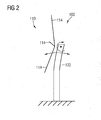
- FIG. 2 shows a side view of a wind turbine 100, the tower 120 of which performs a fore-aft oscillatory movement.
- the oscillatory movement of the top of the tower 120 which is indicated by a curved double arrow, is associated with a mechanical torque acting on the top of the tower 120.
- this torque is represented by a vector being oriented perpendicular to the plane of projection.
- Figure 2 in which this mechanical torque is indicated by a bent arrow, depicts the tower 120 at a phasing, where the top of the tower 120 moves to the right side.
- the mechanical torque acting on the top of the tower is often referred to as a tower top tilt torque.
- the general principle of the damping method described in this document is that a sinusoidal component in the tower top tilt torque can be generated by using the gyroscopic forces when yawing the rotor 110.
- the tower top tilt torque which is generated during yawing can be calculated from the rotational inertia of the rotor 110 scaled by the cross product of the rotor speed and the yaw speed.
- FIG. 3 shows in a block diagram a control device 160 for damping an oscillatory movement of the tower top of a wind turbine.
- the control device 160 implements a fore-aft damping algorithm for the tower top.
- the principle of the fore-aft damping algorithm is elucidated.
- a corresponding tower movement signal which is input to the control device 160 via an input terminal 162, is amplified with a gain k in an amplifier 364 in order to allow for an adjustment of the output amplitude of the control device 160.
- the amplified signal is then filtered by means of a filter 366. With the filter 366 the frequencies that are damped are limited such that they only include the fundamental tower oscillation frequency.
- the phase of the filtered signal is then corrected by using a variable delay 368 and/or some other filter configurations.
- the value of an operational parameter such as the wind turbine power production, the wind speed, the rotor speed, the pitch angle of the rotor blades, turbulence etc. is used to adjust the overall gain of the damping function of the control device 160.
- This gain adjustment is realized by a multiplier 382.
- a signal representing the value of such an operational parameter is input to the control device 160 via a further input terminal 372 and forwarded to the multiplier 382.
- the signal output from the multiplier 382 is saturated to some maximum values by a signal limiter 384.
- a so called dead zone generating unit 386 is used to apply a dead zone for the output signal of the signal limiter 384.
- the output signal of the algorithm performed with the control device 160 is a yaw speed offset signal which is output at an output terminal 392.
- This yaw speed offset signal can be added to an existing yaw speed reference of a control system of the wind turbine.
- the output may be a reference yaw position signal or a reference yaw acceleration signal, with in an appropriate manner changes the algorithm parameters.
- the offset signal may be used to schedule when to start and when to stop a yawing movement being used for generating the gyroscopic torque.
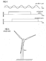
- the upper subplot shows an ideal yaw offset signal as a function of time to provide a maximum damping.
- the middle subplot shows an unscheduled yawing signal in order to face the rotor of the wind turbine into the wind.
- the unscheduled yawing signal has the right sign and the wrong sign respectively for approximately the same amount of time. This yields a net damping effect of zero.
- the lowest subplot shows a scheduled yaw period, where the sign of the yawing signal is correct, and thus provides damping in most of the time yielding a positive damping effect.
- Scheduling the yaw activity in accordance with Figure 4 adds a damping to tower top oscillations without increasing the overall yaw activity or the number of yaw reversals.
- the described yaw strategy it may not be necessary to increase the number of yaw starts and yaw stops or the number of yaw direction changes.
- a scheduled or coordinated yaw movement can be used to damp fore-aft tower oscillations. This can be done effectively by using a sinusoidal yaw offset signal and/or updating the existing control law which will not cause additional yaw activity.
Landscapes
- Engineering & Computer Science (AREA)
- Life Sciences & Earth Sciences (AREA)
- Sustainable Development (AREA)
- Sustainable Energy (AREA)
- Chemical & Material Sciences (AREA)
- Combustion & Propulsion (AREA)
- Mechanical Engineering (AREA)
- General Engineering & Computer Science (AREA)
- Power Engineering (AREA)
- Wind Motors (AREA)
Priority Applications (4)
| Application Number | Priority Date | Filing Date | Title |
|---|---|---|---|
| DK13168207.2T DK2803853T3 (da) | 2013-05-17 | 2013-05-17 | Dæmpning af vindmølletårnsvingninger ved anvendelse af gyroskopiske kræfter |
| EP13168207.2A EP2803853B1 (en) | 2013-05-17 | 2013-05-17 | Damping wind turbine tower oscillations using gyroscopic forces |
| US14/214,792 US9347431B2 (en) | 2013-05-17 | 2014-03-15 | Damping wind turbine tower oscillations using gyroscopic forces |
| CN201410207453.1A CN104165126A (zh) | 2013-05-17 | 2014-05-16 | 使用陀螺力抑制风力涡轮机塔振荡 |
Applications Claiming Priority (1)
| Application Number | Priority Date | Filing Date | Title |
|---|---|---|---|
| EP13168207.2A EP2803853B1 (en) | 2013-05-17 | 2013-05-17 | Damping wind turbine tower oscillations using gyroscopic forces |
Publications (2)
| Publication Number | Publication Date |
|---|---|
| EP2803853A1 EP2803853A1 (en) | 2014-11-19 |
| EP2803853B1 true EP2803853B1 (en) | 2015-09-02 |
Family
ID=48463796
Family Applications (1)
| Application Number | Title | Priority Date | Filing Date |
|---|---|---|---|
| EP13168207.2A Not-in-force EP2803853B1 (en) | 2013-05-17 | 2013-05-17 | Damping wind turbine tower oscillations using gyroscopic forces |
Country Status (4)
| Country | Link |
|---|---|
| US (1) | US9347431B2 (da) |
| EP (1) | EP2803853B1 (da) |
| CN (1) | CN104165126A (da) |
| DK (1) | DK2803853T3 (da) |
Families Citing this family (21)
| Publication number | Priority date | Publication date | Assignee | Title |
|---|---|---|---|---|
| US20150076822A1 (en) * | 2013-09-13 | 2015-03-19 | Justin Creaby | Damping an oscillatory movement of a nacelle of a wind turbine |
| CN104632526B (zh) * | 2015-02-06 | 2017-12-15 | 沈阳华创风能有限公司 | 基于变频器有效阻尼的偏航系统及偏航方法 |
| DK201570134A1 (en) * | 2015-03-10 | 2016-02-01 | Vestas Wind Sys As | Dynamic range control for wind turbine damping system |
| US10907617B2 (en) * | 2016-06-30 | 2021-02-02 | Vestas Wind Systems A/S | Diagnostic system and method for use in a wind turbine |
| EP3545189B1 (en) * | 2016-11-24 | 2021-03-24 | Vestas Wind Systems A/S | Improvements relating to wind turbines having blades equipped with boundary layer control system |
| EP3724488B1 (en) * | 2017-12-14 | 2023-02-01 | Vestas Wind Systems A/S | Tower damping during power production of a wind turbine |
| DE102018005134A1 (de) | 2018-06-28 | 2020-01-02 | Senvion Gmbh | Verfahren und Steuerung zum Betreiben einer Windenergieanlage |
| US11635062B2 (en) | 2018-11-07 | 2023-04-25 | General Electric Renovables Espana, S.L. | Wind turbine and method to determine modal characteristics of the wind turbine in a continuous manner |
| WO2020108716A1 (en) * | 2018-11-27 | 2020-06-04 | Vestas Wind Systems A/S | Nacelle yaw tool for active yaw mitigation of wind induced vibrations |
| WO2020108715A1 (en) * | 2018-11-27 | 2020-06-04 | Vestas Wind Systems A/S | Active yaw mitigation of wind induced vibrations |
| CN111219294B (zh) * | 2018-11-27 | 2022-04-12 | 维斯塔斯风力系统集团公司 | 风致振动的主动偏航缓解 |
| EP3667074A1 (en) * | 2018-12-13 | 2020-06-17 | Siemens Gamesa Renewable Energy A/S | Device and method of damping front and backward movements of a tower of a wind turbine |
| CN113490792B (zh) * | 2018-12-18 | 2024-07-30 | 维斯塔斯风力系统集团公司 | 对风力涡轮机的侧向和前后振动移动的控制 |
| US11208986B2 (en) | 2019-06-27 | 2021-12-28 | Uptake Technologies, Inc. | Computer system and method for detecting irregular yaw activity at a wind turbine |
| US10975841B2 (en) * | 2019-08-02 | 2021-04-13 | Uptake Technologies, Inc. | Computer system and method for detecting rotor imbalance at a wind turbine |
| US11460002B2 (en) * | 2019-10-28 | 2022-10-04 | Siemens Gamesa Renewable Energy A/S | Blade vibration suppression system for a wind turbine and associated method |
| EP3872336A1 (en) * | 2020-02-25 | 2021-09-01 | Siemens Gamesa Renewable Energy A/S | Determining a frequency of an oscillating movement of a wind turbine tower |
| TW202248528A (zh) * | 2021-05-26 | 2022-12-16 | 丹麥商維斯塔斯風力系統有限公司 | 含有具偏移重心之機艙之風力機 |
| CN116044657A (zh) * | 2023-02-21 | 2023-05-02 | 中车株洲电力机车研究所有限公司 | 基于塔筒加速度的风机保护控制方法、系统、介质及设备 |
| CN119532107B (zh) * | 2023-08-30 | 2025-12-19 | 北京金风科创风电设备有限公司 | 风力发电机组及其净空控制方法 |
| CN119244463B (zh) * | 2024-12-06 | 2025-02-14 | 湖南兴蓝风电有限公司 | 一种叶片气动异常检测方法、装置、电子设备及存储介质 |
Family Cites Families (13)
| Publication number | Priority date | Publication date | Assignee | Title |
|---|---|---|---|---|
| US4420692A (en) * | 1982-04-02 | 1983-12-13 | United Technologies Corporation | Motion responsive wind turbine tower damping |
| US4435647A (en) * | 1982-04-02 | 1984-03-06 | United Technologies Corporation | Predicted motion wind turbine tower damping |
| DE29715249U1 (de) * | 1997-08-25 | 1998-12-24 | Institut für Solare Energieversorgungstechnik Verein an der Universität Gesamthochschule Kassel eV, 34119 Kassel | Windenergieanlage |
| JP4814644B2 (ja) * | 2006-02-01 | 2011-11-16 | 富士重工業株式会社 | 風力発電装置 |
| US7942629B2 (en) * | 2008-04-22 | 2011-05-17 | General Electric Company | Systems and methods involving wind turbine towers for power applications |
| ES2374666T3 (es) | 2008-07-16 | 2012-02-20 | Siemens Aktiengesellschaft | Método y disposición para amortiguar oscilaciones de torre. |
| SE535044C2 (sv) * | 2009-03-05 | 2012-03-27 | Ge Wind Energy Norway As | Girsystem för ett vindkraftverk |
| DE102010023887A1 (de) * | 2010-06-15 | 2011-12-15 | Robert Bosch Gmbh | Verfahren und Vorrichtung zur Verhinderung einer Querschwingung einer Windenergieanlage |
| EP2420806A1 (en) * | 2010-08-20 | 2012-02-22 | Siemens Aktiengesellschaft | Method and device for determining a phase value of a phase associated with an oscillatory tower movement of a tower of a wind turbine and method of operating a wind turbine |
| EP2489872B1 (en) * | 2011-02-15 | 2013-03-20 | SSB Wind Systems GmbH & Co. KG | Blade load reduction for wind turbine |
| US9644606B2 (en) * | 2012-06-29 | 2017-05-09 | General Electric Company | Systems and methods to reduce tower oscillations in a wind turbine |
| EP2685093B1 (en) * | 2012-07-10 | 2016-06-29 | Alstom Wind, S.L.U. | Wind turbine stabilization |
| US20150076822A1 (en) * | 2013-09-13 | 2015-03-19 | Justin Creaby | Damping an oscillatory movement of a nacelle of a wind turbine |
-
2013
- 2013-05-17 DK DK13168207.2T patent/DK2803853T3/da active
- 2013-05-17 EP EP13168207.2A patent/EP2803853B1/en not_active Not-in-force
-
2014
- 2014-03-15 US US14/214,792 patent/US9347431B2/en not_active Expired - Fee Related
- 2014-05-16 CN CN201410207453.1A patent/CN104165126A/zh active Pending
Also Published As
| Publication number | Publication date |
|---|---|
| US20140339827A1 (en) | 2014-11-20 |
| CN104165126A (zh) | 2014-11-26 |
| DK2803853T3 (da) | 2015-12-14 |
| US9347431B2 (en) | 2016-05-24 |
| EP2803853A1 (en) | 2014-11-19 |
Similar Documents
| Publication | Publication Date | Title |
|---|---|---|
| EP2803853B1 (en) | Damping wind turbine tower oscillations using gyroscopic forces | |
| EP3601789B1 (en) | System and method to manage torsional oscillation of a wind turbine tower | |
| US7692322B2 (en) | Wind turbine generator, active damping method thereof, and windmill tower | |
| EP3271576B1 (en) | Damping oscillations in a wind turbine | |
| US9523352B2 (en) | Methods and systems for alleviating the loads generated in wind turbines by wind asymmetries | |
| US9541065B2 (en) | Wind turbine control method using an estimation of the incident wind speed | |
| US20120257967A1 (en) | Method and controller for generating a blade pitch angle control signal and wind turbine comprising the controller | |
| EP2679810B1 (en) | Systems and method to reduce tower oscillations in a wind turbine | |
| EP3821125B1 (en) | Method and system for controlling a wind turbine to reduce nacelle vibration | |
| US8779617B2 (en) | Method for reducing vibrations of a wind turbine and control system for reducing vibrations | |
| US10087913B2 (en) | Controlling motions of floating wind turbines | |
| EP2770195B1 (en) | Wind turbine generator, and control unit and control method of the same | |
| EP3167185B1 (en) | Active promotion of wind turbine tower oscillations | |
| DK2426352T3 (da) | Fremgangsmåde til regulering af omdrejningstallet i et vindenergianlæg | |
| CN104612899B (zh) | 减弱风力涡轮机机舱的振荡运动 | |
| WO2019042515A1 (en) | TORSION VIBRATION DAMPING IN A MULTI-ROTOR WIND TURBINE | |
| CN105899804A (zh) | 抵消空载风力涡轮机的塔架振荡 | |
| JP2024512013A (ja) | 浮体式風力タービンの動作を制御する方法および装置 | |
| EP4077920B1 (en) | Wind turbine control | |
| EP2574775B1 (en) | Method of operating a pitch system of a wind turbine considering tower movement and pitch blade bearing lubrication | |
| KR102411521B1 (ko) | 풍력발전기 타워의 진동저감 제어시스템 | |
| EP4669860A1 (en) | Active depreciation for an offshore wind turbine during idle operation | |
| EP4435253A1 (en) | An active vibration controlling device for a wind turbine |
Legal Events
| Date | Code | Title | Description |
|---|---|---|---|
| PUAI | Public reference made under article 153(3) epc to a published international application that has entered the european phase |
Free format text: ORIGINAL CODE: 0009012 |
|
| 17P | Request for examination filed |
Effective date: 20130517 |
|
| AK | Designated contracting states |
Kind code of ref document: A1 Designated state(s): AL AT BE BG CH CY CZ DE DK EE ES FI FR GB GR HR HU IE IS IT LI LT LU LV MC MK MT NL NO PL PT RO RS SE SI SK SM TR |
|
| AX | Request for extension of the european patent |
Extension state: BA ME |
|
| R17P | Request for examination filed (corrected) |
Effective date: 20141106 |
|
| RBV | Designated contracting states (corrected) |
Designated state(s): AL AT BE BG CH CY CZ DE DK EE ES FI FR GB GR HR HU IE IS IT LI LT LU LV MC MK MT NL NO PL PT RO RS SE SI SK SM TR |
|
| GRAP | Despatch of communication of intention to grant a patent |
Free format text: ORIGINAL CODE: EPIDOSNIGR1 |
|
| RIC1 | Information provided on ipc code assigned before grant |
Ipc: F03D 7/02 20060101AFI20150302BHEP |
|
| INTG | Intention to grant announced |
Effective date: 20150325 |
|
| GRAS | Grant fee paid |
Free format text: ORIGINAL CODE: EPIDOSNIGR3 |
|
| GRAA | (expected) grant |
Free format text: ORIGINAL CODE: 0009210 |
|
| AK | Designated contracting states |
Kind code of ref document: B1 Designated state(s): AL AT BE BG CH CY CZ DE DK EE ES FI FR GB GR HR HU IE IS IT LI LT LU LV MC MK MT NL NO PL PT RO RS SE SI SK SM TR |
|
| REG | Reference to a national code |
Ref country code: GB Ref legal event code: FG4D |
|
| REG | Reference to a national code |
Ref country code: AT Ref legal event code: REF Ref document number: 746787 Country of ref document: AT Kind code of ref document: T Effective date: 20150915 Ref country code: CH Ref legal event code: EP |
|
| REG | Reference to a national code |
Ref country code: IE Ref legal event code: FG4D |
|
| REG | Reference to a national code |
Ref country code: DE Ref legal event code: R096 Ref document number: 602013002791 Country of ref document: DE |
|
| REG | Reference to a national code |
Ref country code: DK Ref legal event code: T3 Effective date: 20151210 |
|
| REG | Reference to a national code |
Ref country code: AT Ref legal event code: MK05 Ref document number: 746787 Country of ref document: AT Kind code of ref document: T Effective date: 20150902 |
|
| PG25 | Lapsed in a contracting state [announced via postgrant information from national office to epo] |
Ref country code: LV Free format text: LAPSE BECAUSE OF FAILURE TO SUBMIT A TRANSLATION OF THE DESCRIPTION OR TO PAY THE FEE WITHIN THE PRESCRIBED TIME-LIMIT Effective date: 20150902 Ref country code: FI Free format text: LAPSE BECAUSE OF FAILURE TO SUBMIT A TRANSLATION OF THE DESCRIPTION OR TO PAY THE FEE WITHIN THE PRESCRIBED TIME-LIMIT Effective date: 20150902 Ref country code: GR Free format text: LAPSE BECAUSE OF FAILURE TO SUBMIT A TRANSLATION OF THE DESCRIPTION OR TO PAY THE FEE WITHIN THE PRESCRIBED TIME-LIMIT Effective date: 20151203 Ref country code: LT Free format text: LAPSE BECAUSE OF FAILURE TO SUBMIT A TRANSLATION OF THE DESCRIPTION OR TO PAY THE FEE WITHIN THE PRESCRIBED TIME-LIMIT Effective date: 20150902 Ref country code: NO Free format text: LAPSE BECAUSE OF FAILURE TO SUBMIT A TRANSLATION OF THE DESCRIPTION OR TO PAY THE FEE WITHIN THE PRESCRIBED TIME-LIMIT Effective date: 20151202 |
|
| REG | Reference to a national code |
Ref country code: LT Ref legal event code: MG4D Ref country code: NL Ref legal event code: MP Effective date: 20150902 |
|
| PG25 | Lapsed in a contracting state [announced via postgrant information from national office to epo] |
Ref country code: RS Free format text: LAPSE BECAUSE OF FAILURE TO SUBMIT A TRANSLATION OF THE DESCRIPTION OR TO PAY THE FEE WITHIN THE PRESCRIBED TIME-LIMIT Effective date: 20150902 Ref country code: AT Free format text: LAPSE BECAUSE OF FAILURE TO SUBMIT A TRANSLATION OF THE DESCRIPTION OR TO PAY THE FEE WITHIN THE PRESCRIBED TIME-LIMIT Effective date: 20150902 Ref country code: SE Free format text: LAPSE BECAUSE OF FAILURE TO SUBMIT A TRANSLATION OF THE DESCRIPTION OR TO PAY THE FEE WITHIN THE PRESCRIBED TIME-LIMIT Effective date: 20150902 Ref country code: PL Free format text: LAPSE BECAUSE OF FAILURE TO SUBMIT A TRANSLATION OF THE DESCRIPTION OR TO PAY THE FEE WITHIN THE PRESCRIBED TIME-LIMIT Effective date: 20150902 |
|
| PG25 | Lapsed in a contracting state [announced via postgrant information from national office to epo] |
Ref country code: CZ Free format text: LAPSE BECAUSE OF FAILURE TO SUBMIT A TRANSLATION OF THE DESCRIPTION OR TO PAY THE FEE WITHIN THE PRESCRIBED TIME-LIMIT Effective date: 20150902 Ref country code: SK Free format text: LAPSE BECAUSE OF FAILURE TO SUBMIT A TRANSLATION OF THE DESCRIPTION OR TO PAY THE FEE WITHIN THE PRESCRIBED TIME-LIMIT Effective date: 20150902 Ref country code: IS Free format text: LAPSE BECAUSE OF FAILURE TO SUBMIT A TRANSLATION OF THE DESCRIPTION OR TO PAY THE FEE WITHIN THE PRESCRIBED TIME-LIMIT Effective date: 20160102 Ref country code: EE Free format text: LAPSE BECAUSE OF FAILURE TO SUBMIT A TRANSLATION OF THE DESCRIPTION OR TO PAY THE FEE WITHIN THE PRESCRIBED TIME-LIMIT Effective date: 20150902 Ref country code: IT Free format text: LAPSE BECAUSE OF FAILURE TO SUBMIT A TRANSLATION OF THE DESCRIPTION OR TO PAY THE FEE WITHIN THE PRESCRIBED TIME-LIMIT Effective date: 20150902 Ref country code: NL Free format text: LAPSE BECAUSE OF FAILURE TO SUBMIT A TRANSLATION OF THE DESCRIPTION OR TO PAY THE FEE WITHIN THE PRESCRIBED TIME-LIMIT Effective date: 20150902 |
|
| REG | Reference to a national code |
Ref country code: FR Ref legal event code: PLFP Year of fee payment: 4 |
|
| PG25 | Lapsed in a contracting state [announced via postgrant information from national office to epo] |
Ref country code: RO Free format text: LAPSE BECAUSE OF FAILURE TO SUBMIT A TRANSLATION OF THE DESCRIPTION OR TO PAY THE FEE WITHIN THE PRESCRIBED TIME-LIMIT Effective date: 20150902 Ref country code: PT Free format text: LAPSE BECAUSE OF FAILURE TO SUBMIT A TRANSLATION OF THE DESCRIPTION OR TO PAY THE FEE WITHIN THE PRESCRIBED TIME-LIMIT Effective date: 20160104 |
|
| REG | Reference to a national code |
Ref country code: DE Ref legal event code: R097 Ref document number: 602013002791 Country of ref document: DE |
|
| PLBE | No opposition filed within time limit |
Free format text: ORIGINAL CODE: 0009261 |
|
| STAA | Information on the status of an ep patent application or granted ep patent |
Free format text: STATUS: NO OPPOSITION FILED WITHIN TIME LIMIT |
|
| 26N | No opposition filed |
Effective date: 20160603 |
|
| PG25 | Lapsed in a contracting state [announced via postgrant information from national office to epo] |
Ref country code: SI Free format text: LAPSE BECAUSE OF FAILURE TO SUBMIT A TRANSLATION OF THE DESCRIPTION OR TO PAY THE FEE WITHIN THE PRESCRIBED TIME-LIMIT Effective date: 20150902 Ref country code: BE Free format text: LAPSE BECAUSE OF NON-PAYMENT OF DUE FEES Effective date: 20160531 |
|
| PG25 | Lapsed in a contracting state [announced via postgrant information from national office to epo] |
Ref country code: LU Free format text: LAPSE BECAUSE OF FAILURE TO SUBMIT A TRANSLATION OF THE DESCRIPTION OR TO PAY THE FEE WITHIN THE PRESCRIBED TIME-LIMIT Effective date: 20160517 Ref country code: BE Free format text: LAPSE BECAUSE OF FAILURE TO SUBMIT A TRANSLATION OF THE DESCRIPTION OR TO PAY THE FEE WITHIN THE PRESCRIBED TIME-LIMIT Effective date: 20150902 |
|
| REG | Reference to a national code |
Ref country code: CH Ref legal event code: PL |
|
| PG25 | Lapsed in a contracting state [announced via postgrant information from national office to epo] |
Ref country code: LI Free format text: LAPSE BECAUSE OF NON-PAYMENT OF DUE FEES Effective date: 20160531 Ref country code: CH Free format text: LAPSE BECAUSE OF NON-PAYMENT OF DUE FEES Effective date: 20160531 |
|
| REG | Reference to a national code |
Ref country code: IE Ref legal event code: MM4A |
|
| REG | Reference to a national code |
Ref country code: FR Ref legal event code: PLFP Year of fee payment: 5 |
|
| PG25 | Lapsed in a contracting state [announced via postgrant information from national office to epo] |
Ref country code: IE Free format text: LAPSE BECAUSE OF NON-PAYMENT OF DUE FEES Effective date: 20160517 |
|
| REG | Reference to a national code |
Ref country code: FR Ref legal event code: PLFP Year of fee payment: 6 |
|
| PG25 | Lapsed in a contracting state [announced via postgrant information from national office to epo] |
Ref country code: HU Free format text: LAPSE BECAUSE OF FAILURE TO SUBMIT A TRANSLATION OF THE DESCRIPTION OR TO PAY THE FEE WITHIN THE PRESCRIBED TIME-LIMIT; INVALID AB INITIO Effective date: 20130517 Ref country code: SM Free format text: LAPSE BECAUSE OF FAILURE TO SUBMIT A TRANSLATION OF THE DESCRIPTION OR TO PAY THE FEE WITHIN THE PRESCRIBED TIME-LIMIT Effective date: 20150902 Ref country code: ES Free format text: LAPSE BECAUSE OF FAILURE TO SUBMIT A TRANSLATION OF THE DESCRIPTION OR TO PAY THE FEE WITHIN THE PRESCRIBED TIME-LIMIT Effective date: 20150902 |
|
| PG25 | Lapsed in a contracting state [announced via postgrant information from national office to epo] |
Ref country code: MT Free format text: LAPSE BECAUSE OF NON-PAYMENT OF DUE FEES Effective date: 20160531 Ref country code: MC Free format text: LAPSE BECAUSE OF FAILURE TO SUBMIT A TRANSLATION OF THE DESCRIPTION OR TO PAY THE FEE WITHIN THE PRESCRIBED TIME-LIMIT Effective date: 20150902 Ref country code: MK Free format text: LAPSE BECAUSE OF FAILURE TO SUBMIT A TRANSLATION OF THE DESCRIPTION OR TO PAY THE FEE WITHIN THE PRESCRIBED TIME-LIMIT Effective date: 20150902 Ref country code: HR Free format text: LAPSE BECAUSE OF FAILURE TO SUBMIT A TRANSLATION OF THE DESCRIPTION OR TO PAY THE FEE WITHIN THE PRESCRIBED TIME-LIMIT Effective date: 20150902 Ref country code: CY Free format text: LAPSE BECAUSE OF FAILURE TO SUBMIT A TRANSLATION OF THE DESCRIPTION OR TO PAY THE FEE WITHIN THE PRESCRIBED TIME-LIMIT Effective date: 20150902 |
|
| PG25 | Lapsed in a contracting state [announced via postgrant information from national office to epo] |
Ref country code: BG Free format text: LAPSE BECAUSE OF FAILURE TO SUBMIT A TRANSLATION OF THE DESCRIPTION OR TO PAY THE FEE WITHIN THE PRESCRIBED TIME-LIMIT Effective date: 20150902 |
|
| PGFP | Annual fee paid to national office [announced via postgrant information from national office to epo] |
Ref country code: DK Payment date: 20180518 Year of fee payment: 6 |
|
| PGFP | Annual fee paid to national office [announced via postgrant information from national office to epo] |
Ref country code: FR Payment date: 20180516 Year of fee payment: 6 |
|
| PG25 | Lapsed in a contracting state [announced via postgrant information from national office to epo] |
Ref country code: AL Free format text: LAPSE BECAUSE OF FAILURE TO SUBMIT A TRANSLATION OF THE DESCRIPTION OR TO PAY THE FEE WITHIN THE PRESCRIBED TIME-LIMIT Effective date: 20150902 Ref country code: TR Free format text: LAPSE BECAUSE OF FAILURE TO SUBMIT A TRANSLATION OF THE DESCRIPTION OR TO PAY THE FEE WITHIN THE PRESCRIBED TIME-LIMIT Effective date: 20150902 |
|
| PGFP | Annual fee paid to national office [announced via postgrant information from national office to epo] |
Ref country code: DE Payment date: 20180719 Year of fee payment: 6 Ref country code: GB Payment date: 20180516 Year of fee payment: 6 |
|
| REG | Reference to a national code |
Ref country code: DE Ref legal event code: R119 Ref document number: 602013002791 Country of ref document: DE |
|
| REG | Reference to a national code |
Ref country code: DK Ref legal event code: EBP Effective date: 20190531 |
|
| GBPC | Gb: european patent ceased through non-payment of renewal fee |
Effective date: 20190517 |
|
| PG25 | Lapsed in a contracting state [announced via postgrant information from national office to epo] |
Ref country code: GB Free format text: LAPSE BECAUSE OF NON-PAYMENT OF DUE FEES Effective date: 20190517 Ref country code: DK Free format text: LAPSE BECAUSE OF NON-PAYMENT OF DUE FEES Effective date: 20190531 Ref country code: DE Free format text: LAPSE BECAUSE OF NON-PAYMENT OF DUE FEES Effective date: 20191203 |
|
| PG25 | Lapsed in a contracting state [announced via postgrant information from national office to epo] |
Ref country code: FR Free format text: LAPSE BECAUSE OF NON-PAYMENT OF DUE FEES Effective date: 20190531 |