EP2803854B1 - Dispositif de commande de l'angle d'incidence des pales et éolienne - Google Patents
Dispositif de commande de l'angle d'incidence des pales et éolienne Download PDFInfo
- Publication number
- EP2803854B1 EP2803854B1 EP14178243.3A EP14178243A EP2803854B1 EP 2803854 B1 EP2803854 B1 EP 2803854B1 EP 14178243 A EP14178243 A EP 14178243A EP 2803854 B1 EP2803854 B1 EP 2803854B1
- Authority
- EP
- European Patent Office
- Prior art keywords
- angle
- pitch
- blade
- load
- command
- Prior art date
- Legal status (The legal status is an assumption and is not a legal conclusion. Google has not performed a legal analysis and makes no representation as to the accuracy of the status listed.)
- Expired - Lifetime
Links
- 238000004458 analytical method Methods 0.000 claims description 27
- 238000004364 calculation method Methods 0.000 claims description 24
- 238000005259 measurement Methods 0.000 claims description 9
- 230000014509 gene expression Effects 0.000 claims description 6
- 230000000737 periodic effect Effects 0.000 claims description 6
- 238000012546 transfer Methods 0.000 claims description 6
- 230000000694 effects Effects 0.000 description 14
- 238000010248 power generation Methods 0.000 description 13
- 238000012937 correction Methods 0.000 description 10
- 238000000034 method Methods 0.000 description 9
- 230000006870 function Effects 0.000 description 8
- 238000004088 simulation Methods 0.000 description 8
- 230000001133 acceleration Effects 0.000 description 6
- 238000004422 calculation algorithm Methods 0.000 description 6
- 230000007423 decrease Effects 0.000 description 6
- 230000003247 decreasing effect Effects 0.000 description 6
- 238000010586 diagram Methods 0.000 description 6
- 230000007246 mechanism Effects 0.000 description 6
- 230000008569 process Effects 0.000 description 6
- 230000008859 change Effects 0.000 description 4
- 239000013307 optical fiber Substances 0.000 description 3
- 239000000700 radioactive tracer Substances 0.000 description 3
- 238000012360 testing method Methods 0.000 description 3
- 238000013461 design Methods 0.000 description 2
- 239000000428 dust Substances 0.000 description 2
- 239000000284 extract Substances 0.000 description 2
- 239000002245 particle Substances 0.000 description 2
- 230000002123 temporal effect Effects 0.000 description 2
- 238000013519 translation Methods 0.000 description 2
- XLYOFNOQVPJJNP-UHFFFAOYSA-N water Chemical compound O XLYOFNOQVPJJNP-UHFFFAOYSA-N 0.000 description 2
- 238000007664 blowing Methods 0.000 description 1
- 238000005094 computer simulation Methods 0.000 description 1
- 238000001514 detection method Methods 0.000 description 1
- 238000005516 engineering process Methods 0.000 description 1
- 238000000605 extraction Methods 0.000 description 1
- 238000012545 processing Methods 0.000 description 1
- 238000004904 shortening Methods 0.000 description 1
- 238000011144 upstream manufacturing Methods 0.000 description 1
Images






Classifications
-
- F—MECHANICAL ENGINEERING; LIGHTING; HEATING; WEAPONS; BLASTING
- F03—MACHINES OR ENGINES FOR LIQUIDS; WIND, SPRING, OR WEIGHT MOTORS; PRODUCING MECHANICAL POWER OR A REACTIVE PROPULSIVE THRUST, NOT OTHERWISE PROVIDED FOR
- F03D—WIND MOTORS
- F03D7/00—Controlling wind motors
- F03D7/02—Controlling wind motors the wind motors having rotation axis substantially parallel to the air flow entering the rotor
- F03D7/04—Automatic control; Regulation
- F03D7/042—Automatic control; Regulation by means of an electrical or electronic controller
- F03D7/043—Automatic control; Regulation by means of an electrical or electronic controller characterised by the type of control logic
-
- F—MECHANICAL ENGINEERING; LIGHTING; HEATING; WEAPONS; BLASTING
- F03—MACHINES OR ENGINES FOR LIQUIDS; WIND, SPRING, OR WEIGHT MOTORS; PRODUCING MECHANICAL POWER OR A REACTIVE PROPULSIVE THRUST, NOT OTHERWISE PROVIDED FOR
- F03D—WIND MOTORS
- F03D7/00—Controlling wind motors
- F03D7/02—Controlling wind motors the wind motors having rotation axis substantially parallel to the air flow entering the rotor
- F03D7/04—Automatic control; Regulation
-
- F—MECHANICAL ENGINEERING; LIGHTING; HEATING; WEAPONS; BLASTING
- F03—MACHINES OR ENGINES FOR LIQUIDS; WIND, SPRING, OR WEIGHT MOTORS; PRODUCING MECHANICAL POWER OR A REACTIVE PROPULSIVE THRUST, NOT OTHERWISE PROVIDED FOR
- F03D—WIND MOTORS
- F03D7/00—Controlling wind motors
- F03D7/02—Controlling wind motors the wind motors having rotation axis substantially parallel to the air flow entering the rotor
- F03D7/022—Adjusting aerodynamic properties of the blades
- F03D7/0224—Adjusting blade pitch
-
- F—MECHANICAL ENGINEERING; LIGHTING; HEATING; WEAPONS; BLASTING
- F03—MACHINES OR ENGINES FOR LIQUIDS; WIND, SPRING, OR WEIGHT MOTORS; PRODUCING MECHANICAL POWER OR A REACTIVE PROPULSIVE THRUST, NOT OTHERWISE PROVIDED FOR
- F03D—WIND MOTORS
- F03D7/00—Controlling wind motors
- F03D7/02—Controlling wind motors the wind motors having rotation axis substantially parallel to the air flow entering the rotor
- F03D7/022—Adjusting aerodynamic properties of the blades
- F03D7/024—Adjusting aerodynamic properties of the blades of individual blades
-
- F—MECHANICAL ENGINEERING; LIGHTING; HEATING; WEAPONS; BLASTING
- F05—INDEXING SCHEMES RELATING TO ENGINES OR PUMPS IN VARIOUS SUBCLASSES OF CLASSES F01-F04
- F05B—INDEXING SCHEME RELATING TO WIND, SPRING, WEIGHT, INERTIA OR LIKE MOTORS, TO MACHINES OR ENGINES FOR LIQUIDS COVERED BY SUBCLASSES F03B, F03D AND F03G
- F05B2270/00—Control
- F05B2270/30—Control parameters, e.g. input parameters
- F05B2270/32—Wind speeds
-
- F—MECHANICAL ENGINEERING; LIGHTING; HEATING; WEAPONS; BLASTING
- F05—INDEXING SCHEMES RELATING TO ENGINES OR PUMPS IN VARIOUS SUBCLASSES OF CLASSES F01-F04
- F05B—INDEXING SCHEME RELATING TO WIND, SPRING, WEIGHT, INERTIA OR LIKE MOTORS, TO MACHINES OR ENGINES FOR LIQUIDS COVERED BY SUBCLASSES F03B, F03D AND F03G
- F05B2270/00—Control
- F05B2270/30—Control parameters, e.g. input parameters
- F05B2270/326—Rotor angle
-
- F—MECHANICAL ENGINEERING; LIGHTING; HEATING; WEAPONS; BLASTING
- F05—INDEXING SCHEMES RELATING TO ENGINES OR PUMPS IN VARIOUS SUBCLASSES OF CLASSES F01-F04
- F05B—INDEXING SCHEME RELATING TO WIND, SPRING, WEIGHT, INERTIA OR LIKE MOTORS, TO MACHINES OR ENGINES FOR LIQUIDS COVERED BY SUBCLASSES F03B, F03D AND F03G
- F05B2270/00—Control
- F05B2270/30—Control parameters, e.g. input parameters
- F05B2270/331—Mechanical loads
-
- F—MECHANICAL ENGINEERING; LIGHTING; HEATING; WEAPONS; BLASTING
- F05—INDEXING SCHEMES RELATING TO ENGINES OR PUMPS IN VARIOUS SUBCLASSES OF CLASSES F01-F04
- F05B—INDEXING SCHEME RELATING TO WIND, SPRING, WEIGHT, INERTIA OR LIKE MOTORS, TO MACHINES OR ENGINES FOR LIQUIDS COVERED BY SUBCLASSES F03B, F03D AND F03G
- F05B2270/00—Control
- F05B2270/30—Control parameters, e.g. input parameters
- F05B2270/335—Output power or torque
-
- Y—GENERAL TAGGING OF NEW TECHNOLOGICAL DEVELOPMENTS; GENERAL TAGGING OF CROSS-SECTIONAL TECHNOLOGIES SPANNING OVER SEVERAL SECTIONS OF THE IPC; TECHNICAL SUBJECTS COVERED BY FORMER USPC CROSS-REFERENCE ART COLLECTIONS [XRACs] AND DIGESTS
- Y02—TECHNOLOGIES OR APPLICATIONS FOR MITIGATION OR ADAPTATION AGAINST CLIMATE CHANGE
- Y02E—REDUCTION OF GREENHOUSE GAS [GHG] EMISSIONS, RELATED TO ENERGY GENERATION, TRANSMISSION OR DISTRIBUTION
- Y02E10/00—Energy generation through renewable energy sources
- Y02E10/70—Wind energy
- Y02E10/72—Wind turbines with rotation axis in wind direction
Definitions
- the present invention relates to a wind power generator, and in particular, to a blade-pitch-angle control device for controlling a blade-pitch-angle of a windmill.
- a known propeller windmill used in wind power generators includes, for example, three blades composed of a first blade 1, a second blade 2, and a third blade 3, a rotor 5 serving as a link mechanism for linking the three blades, a tower 4, and so on.
- each of the blades of such a propeller windmill is controlled depending on the wind conditions so as to obtain a predetermined rotational speed and output of a power generator.
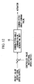
- Fig. 12 shows an example of the structure of a known pitch-angle control device.
- the known pitch-angle control device includes a common-pitch-angle command-value generating unit 15 for generating a common-pitch-angle command value on the basis of the difference between a preset value of a rotational speed or output of a power generator and a controlled value at that time.
- Actuators control each blade so as to have identical pitch-angles on the basis of the common-pitch-angle command value generated by the common-pitch-angle command-value generating unit 15, thus controlling the pitch-angle of the blades.
- the inflow wind speed to a windmill is affected by the ground, as shown in Fig. 13A (the wind speed characteristics affected by the ground are hereinafter referred to as “wind shear characteristics"), or by the tower supporting the windmill, as shown in Fig. 13B (the wind speed characteristics affected by the tower are hereinafter referred to as “tower characteristics”).
- Wind shear characteristics the wind speed characteristics affected by the ground are hereinafter referred to as "wind shear characteristics”
- the tower supporting the windmill as shown in Fig. 13B
- the wind speed characteristics affected by the tower are hereinafter referred to as “tower characteristics”
- Spatial disorder and temporal disorder of the wind speed are added to the effects described above, resulting in an uneven wind speed distribution in the blade rotation area, as shown in Fig. 13C .
- the values of the thrust, the moment, and the like of the blades are also different from each other.
- a load fluctuation in each blade occurs, thereby shortening the lifetime of the blades.
- Patent Document 1 discloses a technology in which the angle of attack of wind flowing to each blade and the load are measured, and the blades are individually controlled on the basis of these values.
- the load applied to each part of a wind power generator, the angle of attack of wind flowing to the blades, and the like are instantaneously calculated on the basis of detected values from a plurality of sensors, and the pitch-angle is controlled so as to decrease the instantaneous load fluctuation.
- the pitch-angle is controlled so as to decrease the instantaneous load fluctuation.
- a series of processes from detection by the sensors to feedback control must be performed substantially in real time.
- the present invention has been made in order to solve the above problems, and it is an object of the present invention to provide a pitch-angle control device in which a load fluctuation generated in a wind power generator can be further decreased by improving the accuracy of pitch-angle control.
- the present invention provides the following solutions.
- the present invention provides a blade-pitch-angle control device used for a wind power generator having a plurality of blades, the blade-pitch-angle control device comprising:
- the load-measuring devices measure the load not at predetermined time intervals but at predetermined azimuth-angles
- the load-measuring devices can be applied not only to constant-speed windmills but also to variable-speed windmills in which the rotational speed of the blades changes depending on the operational state.
- the adjusting pitch-angle command-value generating device calculates the optimum pitch-angle for each blade for reducing the load measured by each of the load-measuring devices to generate adjusting pitch-angle command-values.
- the pitch-angle-control command-value generating device causes these adjusting pitch-angle command-values to be reflected in the pitch-angle-control command-values for controlling the pitch angles of the blades. Thereby, the load fluctuation can be decreased.
- the present inventors focus on the fact that a significant load fluctuation of the blades periodically occurs. Consequently, the load-measuring devices and the calculation device are provided as devices that detect the load fluctuation during one revolution of a rotor.
- the load-measuring devices measure a load applied to each of the blades at predetermined azimuth angles.
- the load-measuring devices can be applied to variable-speed windmills in which the rotational speed of the blades changes.
- the calculation device obtains measured values measured with the load-measuring devices at each azimuth angle, the measured values corresponding to a predetermined period (for example, corresponding to one revolution), and determines the characteristics of the load on the basis of the measured values. Thus, information on the load fluctuation in each blade can be obtained.
- the adjusting pitch-angle command-value generating device calculates the adjusting pitch-angle command values for eliminating the load fluctuation, and the pitch-angle-control command-value generating device causes these adjusting pitch-angle command values to be reflected in the control of the pitch angle of each blade. Thereby, the significant load fluctuation that periodically occurs can be reduced.
- the load fluctuation is decreased by focusing on the load fluctuation that periodically occurs, the load fluctuation can be efficiently decreased by a process much simpler than the conventional pitch-angle control that decreases instantaneous load fluctuations. Consequently, each blade can be controlled so as to have the optimum pitch-angle, and the lifetime of the blades and mechanical parts constituting the windmill can be extended.
- the load fluctuation that is focused on by the present invention periodically occurs at substantially the same azimuth angle. Therefore, even when the time-lag due to the feedback control occurs, the load fluctuation can be eliminated with high accuracy.
- each of the load-measuring devices preferably includes an azimuth-angle measuring device that measures the azimuth angle of each blade at predetermined time intervals, a trigger-generating device that generates a trigger signal when the measurement result matches a predetermined azimuth angle, and a measuring device that measures a load on the basis of the trigger signal.
- the load-measuring devices include generally well known mechanisms, the load-measuring devices can be achieved simply and at low cost.
- Examples of the measuring device include a strain gauge, a load cell, and an optical fiber sensor.
- each of the load-measuring devices preferably includes an encoder that generates a trigger when the azimuth angle reaches a predetermined angle and a measuring device that measures a load on the basis the trigger.
- the encoder and the measuring device are generally well known mechanisms.
- the load-measuring devices include generally well known mechanisms, the load-measuring devices can be achieved simply and at low cost.
- Examples of the measuring device include a strain gauge, a load cell, and an optical fiber sensor.
- the present disclosure provides a wind power generator having a plurality of blades, the wind power generator including a blade-pitch-angle control device according to any one of claims 1-6.
- each blade can be controlled so as to have the optimum pitch-angle and a wind power generator including long-life blades and mechanical parts constituting a windmill can be realized.
- Fig. 1 is a block diagram showing the structure of a blade-pitch-angle control device that is applied to a wind power generator using a constant-speed windmill.
- such a blade-pitch-angle control device includes a memory unit (memory device) 10, an azimuth-angle detecting unit (azimuth-angle detecting device) 11, a parameter-detecting unit (parameter-detecting device) 12, a command-value receiving unit (command-value receiving device) 13, a pitch-angle-control command-value generating unit (pitch-angle-control command-value generating device) 14, and a common-pitch-angle command-value generating unit (common-pitch-angle command-value generating device) 15.
- a memory unit memory device
- azimuth-angle detecting unit azimuth-angle detecting device
- parameter-detecting unit parameter-detecting unit
- command-value receiving unit command-value receiving device
- pitch-angle-control command-value generating unit pitch-angle-control command-value generating unit
- common-pitch-angle command-value generating unit common-pitch-angle command-value generating unit
- predetermined parameters that affect the load fluctuation of blades for example, wind speed, temperature, and output of the wind power generator; azimuth angles; and pitch-angle command values are stored in association with each other.
- the azimuth angle represents an angle formed relative to the vertical direction of the windmill.
- the azimuth angle when a blade is located at the top of the windmill is defined as 0°
- the azimuth angle when the blade is located at the bottom of the windmill is defined as 180°.
- the azimuth-angle detecting unit 11 detects the azimuth angle of each blade at predetermined intervals and outputs it to the command-value receiving unit 13.
- the azimuth angle can be determined from an output of a rotary encoder provided on a rotation axis.
- the parameter-detecting unit 12 includes a wind-speed detecting unit (wind-speed detecting device) 121 that detects wind speed, an air-density detecting unit 122 that detects air density, and a wind-power-generator-output detecting unit 123 that detects the output of the wind power generator.
- a wind-speed detecting unit wind-speed detecting device
- an air-density detecting unit 122 that detects air density
- a wind-power-generator-output detecting unit 123 that detects the output of the wind power generator.
- the wind-speed detecting unit 121 includes a characteristic table (refer to Fig. 3 ) in which wind speed is related with the output of the wind power generator.
- the wind-speed detecting unit 121 receives the output of the wind power generator from the wind-power-generator-output detecting unit 123 at predetermined intervals. A wind speed corresponding to the output is read out from the characteristic table to estimate the wind speed.
- the estimated wind speed is output to the command-value receiving unit 13.
- an anemometer such as a laser Doppler anemometer
- this configuration is not affected by the airflow behind the blades, highly accurate wind speed can be obtained.
- a device for supplying tracer particles from upstream of the windmill toward the windmill is provided.
- dust or water vapor mixed in air that flows to the windmill may be used as a tracer to obtain scattered light from the dust or the water vapor, and thus laser Doppler measurement may be performed.
- the device for supplying tracer particles need not be separately provided.
- the air-density detecting unit 122 measures air temperature and air pressure at predetermined intervals, and determines the air density from the measured values on the basis of the characteristics of the air density, the air temperature, and the air pressure.
- the air density can be uniquely determined by the air temperature and the air pressure.
- the air-density detecting unit 122 has a map in which air temperature, air pressure, and air density are related with each other in advance. An air density selected by measured values of air temperature and air pressure is obtained from the map, thus determining the air density.
- the air-density detecting unit 122 may have a relational expression including air temperature, air pressure, and air density. The air density may be calculated by substituting measured values of air temperature and air pressure in the relational expression.
- the command-value receiving unit 13 receives pitch-angle command values from the memory unit 10.
- the pitch-angle command values are selected on the basis of azimuth angles of the blades input from the azimuth-angle detecting unit 11 and various parameters (such as wind speed, air density, and power generation output) input from the parameter-detecting unit 12.
- the command-value receiving unit 13 outputs the pitch-angle command values of the blades, i.e., a first-blade-pitch-angle command value, a second-blade-pitch-angle command value, and a third-blade-pitch-angle command value, to the pitch-angle-control command-value generating unit 14.
- the common-pitch-angle command-value generating unit 15 calculates a common-pitch-angle command value for commonly controlling pitch-angles of the three blades, i.e., the first blade to the third blade, from the difference between the preset values of the number of revolutions of the power generator (information on power generation output) or the power generation output (information on power generation output) and the controlled value at that time so that the power generation output of the wind power generator corresponds with the rated output (preset value), and outputs the common-pitch-angle command value to the pitch-angle-control command-value generating unit 14.
- the common-pitch-angle command-value generating unit 15 is composed of a known PID control system.
- the pitch-angle-control command-value generating unit 14 generates pitch-angle-control command values for individually controlling the pitch-angles of the blades on the basis of the pitch-angle command value for each blade input from the command-value receiving unit 13 and the common-pitch-angle command value input from the common-pitch-angle command-value generating unit 15. Specifically, the pitch-angle-control command value for each blade is generated by adding each of the pitch-angle command values to the common-pitch-angle command value. Subsequently, the pitch-angle-control command-value generating unit 14 outputs the pitch-angle-control command values that are individually obtained for each of the blades to actuators, which are devices for controlling the pitch-angles of the blades.
- the actuator is a known mechanism such as a hydraulic cylinder or an electric motor that is installed in each blade.
- wind speed, air density, output of the wind power generator, and the like are used as parameters and various values are set for these parameters.
- the optimum pitch-angle in various test patterns is determined by a computer simulation.
- the wind speed is set to A (m/s)
- the air density is set to B (g/cm 3 )
- the power generation output is set to C (kW). Data about the fluctuating load when the pitch-angle is varied under these conditions is collected.
- the resulting data is checked to select a pitch-angle that provides the minimum fluctuating load.
- a characteristic table relating the selected pitch-angle and the azimuth angle is prepared.
- the above-described parameters such as wind speed
- the wind shear characteristics and the tower shadow characteristics are uniquely determined depending on the location of the windmill or the windmill structure.
- Fig. 4 shows a characteristic table under steady wind conditions (having a temporally constant and two-dimensionally uniform wind speed).
- the characteristic table includes an abscissa indicating the azimuth angle (deg) and an ordinate indicating the pitch-angle (deg).
- the characteristic table shows a cosine wave in which the maximum pitch-angle (for example, 1°) is located at an azimuth angle of 0° and the minimum pitch-angle (for example, -1°) is located at an azimuth angle of 180°.
- the angles in the figure represent relative values.
- Characteristic tables under various conditions obtained by the above simulation also have a fundamental shape substantially the same as that of the characteristic table shown in Fig. 4 , but have different amplitude and phase.
- a blade of the windmill basically forms an upward angle, expressed as a "tilt angle" (generally about 5°), so that a clearance is provided for preventing the blade from hitting the tower. Because of the effect of this tilt angle, the wind flowing to the windmill generally blows upward.
- tilt angle generally about 5°
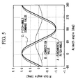
- a pitch-angle correction value for canceling out the effect of the tilt angle on the wind exhibits the characteristics shown in Fig. 5 .
- line A shows a waveform of the fundamental pitch-angle shown in Fig. 4
- line B shows a waveform of the correction value for canceling out the effect of the tilt angle
- line C shows a waveform of a pitch-angle command value obtained by adding the correction value of line B to the waveform of line A.
- the characteristic table obtained when the wind speed is increased in the simulation is a characteristic table in which the upward-blowing wind due to the tilt angle is considered, and has characteristics different from those shown in Fig. 4 , not only in terms of the amplitude but also in terms of the phase.
- the wind direction also affects the load fluctuation of the blade.
- a pitch-angle correction value for canceling out the effect of a deviation in wind direction exhibits the characteristics shown in Fig. 6 .
- line A shows a waveform of the fundamental pitch-angle shown in Fig. 4
- line B shows a waveform of the correction value for canceling out the effect of the deviation in wind direction
- line C shows a waveform of a pitch-angle command value obtained by adding the correction value of line B to the waveform of line A.
- the characteristic table obtained when the wind direction is varied in the simulation is a characteristic table in which the amplitude of the fundamental pitch-angle shown in Fig. 4 changes in the vertical direction.
- Fig. 7 shows a characteristic table when the air density is used as a variable.
- line A shows a waveform of the pitch-angle command value when the air density is high
- line B shows a waveform of the pitch-angle command value when the air density is low.
- a characteristic table having an amplitude larger than the amplitude of the fundamental pitch-angle shown in Fig. 4 is obtained.
- Fig. 8 shows a characteristic table when the output of the wind power generator is used as a variable. In Fig. 8 , line A shows a waveform of the pitch-angle command value when the output is high, and line B shows a waveform of the pitch-angle command value when the output is low.
- the command-value receiving unit 13 receives an azimuth angle from.the azimuth-angle detecting unit 11 and receives the wind speed, air density, and power generator output from the parameter-detecting unit 12, the command-value receiving unit 13 then receives a characteristic table from the memory unit 10, the characteristic table being selected based on the wind speed, the air density, and the power generator output.
- pitch-angle command values corresponding to the azimuth angle of each blade input from the azimuth-angle detecting unit 11 are received.
- pitch-angle command values corresponding to each of the first blade, the second blade, and the third blade can be obtained.
- the command-value receiving unit 13 outputs these pitch-angle command values thus obtained to the pitch-angle-control command-value generating unit 14.
- the pitch-angle-control command-value generating unit 14 generates pitch-angle-control command values for each of the blades by adding the pitch-angle command values input from the command-value receiving unit 13 to the common-pitch-angle command value based on the power generation output of the wind power generator, the common-pitch-angle command value being input from the common-pitch-angle command-value generating unit 15.
- the pitch-angle-control command-value generating unit 14 outputs these pitch-angle-control command values to the respective actuators provided on the corresponding blades.
- the pitch-angle of each blade is controlled so as to be the most suitable angle for the operational state of the wind power generator at that time.
- a characteristic table that most closely approximates the parameter values may be selected.
- a plurality of approximate characteristic tables may be read out and these characteristic tables may be interpolated to determine the pitch-angle command values.
- a blade-pitch-angle control device that is applied to a wind power generator using a constant-speed windmill has been described, but the blade-pitch-angle control device of the present invention can also be applied to a wind power generator using a variable-speed windmill.
- a blade-pitch-angle control device that is applied to a wind power generator using a variable-speed windmill will now be described.
- the number of rotor revolutions is controlled according to the output of the wind power generator.
- the load fluctuation of each blade is also changed by varying the rotational speed (the number of revolutions). Therefore, when such a variable-speed windmill is used, the number of rotor revolutions must also be considered as a parameter.
- the number of rotor revolutions is added as a parameter input to the command-value receiving unit 13, and the memory unit 10 stores characteristic tables in which the number of rotor revolutions is also considered.
- the command-value receiving unit 13 receives a characteristic table from the memory unit 10, the characteristic table being selected by the wind speed, the air density, the power generator output, and the number of rotor revolutions that are input.
- the characteristic table received pitch-angle command values corresponding to the azimuth angle of each blade input from the azimuth-angle detecting unit 11 are received.
- Each of the pitch-angle command values is then output to the pitch-angle-control command-value generating unit 14.
- the subsequent processes are the same as those of the first embodiment described above.
- the above-described blade-pitch-angle control device can significantly reduce the load fluctuation generated in the blades, the device still generates not insignificant output fluctuation. It is known that the frequency band in which such an output fluctuation significantly occurs depends on the number of blades. Accordingly, a pitch-angle for eliminating such a significant output fluctuation is determined and the resulting pitch-angle is reflected in the blade-pitch-angle-control command value, thereby further decreasing the output fluctuation.
- an output-fluctuation eliminating device having the following function is added to the blade-pitch-angle control device shown in Fig. 1 .
- Fig. 9 shows the structure of the output-fluctuation eliminating device that is employed when a constant-speed windmill is used.
- the output-fluctuation eliminating device includes a frequency analysis unit (frequency-component extraction device) 21, a control algorithm (calculation device) 22, an inverse frequency analysis unit (calculation device) 23, and a calculation unit 24.
- the control algorithm 22 obtains the frequency component output from the frequency analysis unit 21 and the azimuth angle detected by the azimuth-angle detecting unit 11 shown in Fig. 1 as input information.
- the control algorithm 22 calculates the information on the basis of a predetermined algorithm to calculate a fluctuating pitch-angle ⁇ ( ⁇ ) in the frequency domain, and outputs the fluctuating pitch-angle ⁇ ( ⁇ ).
- the inverse frequency analysis unit 23 obtains the fluctuating pitch-angle ⁇ ( ⁇ ) calculated by the control algorithm 22 as input information, calculates a fluctuating pitch-angle ⁇ (t) in the time domain by performing an inverse frequency analysis, and outputs the fluctuating pitch-angle ⁇ (t).
- the calculation unit 24 obtains the fluctuating pitch-angle ⁇ (t) in the time domain calculated by the inverse frequency analysis unit 23 and the common-pitch-angle command value output from the common-pitch-angle command-value generating unit 15 (refer to Fig. 1 ) as input information, adds these values so as to finely adjust the common-pitch-angle command value, and outputs the finely adjusted common-pitch-angle command value to the pitch-angle-control command-value generating unit 14 (refer to Fig. 1 ).
- the frequency analysis unit 21 extracts a frequency component that significantly affects the load fluctuation of each blade from the output of the wind power generator.
- the control algorithm 22 and the inverse frequency analysis unit 23 calculate a pitch-angle at which such a frequency component is eliminated.
- the calculation unit 24 reflects the fluctuating pitch-angle output from the inverse frequency analysis unit 23 in the common-pitch-angle command value.
- the number of rotor revolutions is input as an input signal.
- the fluctuating pitch-angle ⁇ (t) is calculated by performing a frequency analysis of the number of rotor revolutions instead of the output.
- the various parameters are not limited to the above-described wind speed, air density, output of the wind power generator, and rotor speed (the number of revolutions), but may include any parameter that affects the output and the like during wind power generation.
- a pitch-angle obtained by considering fluctuations of all the parameters may be used.
- a pitch-angle obtained by considering some of the parameters may be controlled.
- the parameters are not limited to those that are synchronously detected.
- the wind speed and the azimuth angle may be detected at predetermined intervals, and the air density and the like, whose temporal change is small, may be detected at time intervals longer than those used for the wind speed and the azimuth angle.
- a blade-pitch-angle control device according to the present invention will now be described.
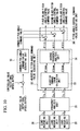
- Fig. 10 is a block diagram showing the structure of a blade-pitch-angle control device that is applied to a wind power generator used in a variable-speed windmill.
- the blade-pitch-angle control device includes load-measuring units (load-measuring devices) 30, a frequency analysis unit (calculation device) 31, an adjusting pitch-angle generating unit (adjusting pitch-angle command-value generating device) 32, a pitch-angle-control command-value generating unit (pitch-angle-control command-value generating device) 36, and a common-pitch-angle command-value generating unit 15.
- Each of the load-measuring units 30 measures a load applied to a corresponding blade at predetermined azimuth angles (for example, every 6°), and outputs the measurement results as an electrical signal.
- the load-measuring unit 30 includes, for example, an azimuth-angle measuring instrument (azimuth-angle measuring device), a trigger-generating circuit (trigger-generating device), and a sensor (measuring device).
- the azimuth-angle measuring instrument measures the azimuth angles of each blade at predetermined time intervals.
- the trigger-generating circuit generates a trigger signal when the measurement result of the azimuth-angle measuring instrument matches a predetermined azimuth angle (for example, an angle that is a multiple of 6°).
- the sensor measures the load on the basis of the trigger signal of the trigger-generating circuit. Examples of the sensor for measuring the load include a strain gauge, a load cell, and an optical fiber sensor that are installed in the blade base portion or a part of the windmill.
- the frequency analysis unit 31 obtains measured values (loads) measured at predetermined azimuth angles as input signals from the load-measuring units 30, and calculates a periodic fluctuation of the load applied to each blade on the basis of the measured values. Specifically, when measured values corresponding to one revolution are obtained, azimuth-angle characteristics of the load are calculated using the following computational expressions (1.1) and (1.2). The azimuth-angle characteristics can be expressed by a cosine component Z ic and a sine component Z is of the load.
- symbol i the blade number.
- i 1, 2, or 3.
- Symbol n an integer that is varied according to the cycle of the load fluctuation to be considered.
- K represents the number of measurements in the azimuth angle range from 0° to 360°.
- Symbol ⁇ represents a value obtained by dividing 360° by K.
- Symbol zi(nk ⁇ ) represents a load value measured at each azimuth angle, which is an input signal from the load-measuring unit 30.
- the adjusting pitch-angle command-value generating unit 32 obtains the analysis results of the frequency analysis unit 31 as input information, and generates an adjusting pitch-angle command value for reducing the load fluctuation for each blade on the basis of the analysis results.
- the adjusting pitch-angle command-value generating unit 32 includes an adjusting command-value calculation unit 33 and an inverse frequency analysis unit 34.
- the adjusting command-value calculation unit 33 obtains the cosine components Z ic and the sine components Z is of the load fluctuation, which are calculated by the frequency analysis unit 31, as input signals, and calculates the input signals Z ic and Z is using a predetermined transfer function. Thereby, an adjusting command value ⁇ dem for eliminating a significant load fluctuation that periodically occurs is calculated for each blade.
- the adjusting command values ⁇ 1 dem, ⁇ 2 dem, and ⁇ 3 dem that are calculated here are values in the frequency domain.
- An example of a method for determining the transfer function used in the adjusting command-value calculation unit 33 is a method in which a simulation is performed while various load fluctuations are assumed, the optimum adjusting command values are obtained by analyzing the simulation results, and a transfer function is determined from the results.
- a plurality of transfer functions may be defined according to the operational state of the windmill.
- the optimum transfer function may be selected according to the operational state of the windmill and used. Thus, more suitable adjusting command values can be determined.
- the inverse frequency analysis unit 34 converts the adjusting command values ⁇ 1 dem, ⁇ 2 dem, and ⁇ 3 dem, which are calculated by the adjusting command-value calculation unit 33 and which are values in the frequency domain, into values in the time domain.
- these adjusting command values are values calculated on the basis of the loads measured by the load-measuring units 30 at predetermined azimuth angles. Therefore, information handled by the frequency analysis unit 31 and the adjusting command-value calculation unit 33 includes characteristics and adjusting command values that are obtained by the change in angle.
- a common-pitch-angle command value determined by the common-pitch-angle command-value generating unit 15, which will be described below, is a command value obtained by the change in time, that is, a time-base command value. Therefore, these command values must be consistent with each other.
- the inverse frequency analysis unit 34 converts the adjusting command values ⁇ 1 dem, ⁇ 2 dem, and ⁇ 3 dem into values ⁇ 1 (t), ⁇ 2 (t), and ⁇ 3 (t), respectively, in the time domain using information on the azimuth angle at that time and a predetermined function.
- the inverse frequency analysis unit 34 transmits the converted adjusting command values ⁇ 1 (t), ⁇ 2 (t), and ⁇ 3 (t) as adjusting pitch-angle command values to the pitch-angle-control command-value generating unit 36.
- the adjusting pitch-angle command values for reducing the load fluctuation are input from the adjusting pitch-angle command-value generating unit 32 to the pitch-angle-control command-value generating unit 36.
- the common-pitch-angle command value is also input as a feedback control value for matching the output at that time with a target value from the common-pitch-angle command-value generating unit 36 to the pitch-angle-control command-value generating unit 36.
- This common-pitch-angle command value is a command value that is common to each blade.
- the pitch-angle-control command-value generating unit 36 adds the input common-pitch-angle command value to each of the adjusting pitch-angle command values ⁇ 1 (t), ⁇ 2 (t), and ⁇ 3 (t) for each blade, thereby generating pitch-angle-control command values for individually controlling the pitch angle of each blade.
- the pitch-angle-control command-value generating unit 36 then outputs the pitch-angle-control command values to the actuators that control the pitch-angle of each blade.
- the blade-pitch-angle control device provides the following advantages.
- this device can be advantageously applied not only to a constant-speed windmill but also to a variable-speed windmill, in which the rotational speed of the blades changes depending on the operational state.
- the load-measuring units 30 measure the load applied to each blade at predetermined azimuth angles
- the frequency analysis unit 31 analyzes the periodic fluctuation characteristics of the load
- the adjusting pitch-angle command-value generating unit 32 determines the adjusting pitch-angle command values for eliminating the load fluctuation on the basis of the analysis results
- the pitch-angle-control command-value generating unit 36 causes these adjusting pitch-angle command values to be reflected in the control of the pitch-angle of each blade.
- this device focuses on the fact that a significant load fluctuation of the blades periodically occurs and aims at reducing the periodic load fluctuation. Therefore, even when a time-lag due to the feedback control occurs, the fluctuating load can be eliminated with high accuracy. Thereby, the load fluctuation can be efficiently reduced by a process much simpler than the conventional pitch-angle control that reduces instantaneous load fluctuations. Consequently, each blade can be controlled so as to have the optimum pitch-angle and the lifetime of the blades and mechanical parts constituting the windmill can be extended.
- the load-measuring unit 30 includes an azimuth-angle measuring instrument that measures the azimuth angle of each blade at predetermined time intervals, a trigger-generator that generates a trigger signal when the measurement result matches a predetermined azimuth angle, and a sensor that measures the load on the basis of the trigger signal, the load-measuring unit 30 can be simply realized.
- the load-measuring unit 30 may include, for example, an encoder that generates a trigger when the azimuth angle reaches a predetermined angle and a sensor that measures the load on the basis the trigger. Since such an encoder and a sensor are generally well known mechanisms, the load-measuring device can be simply realized.
- the acceleration of the blades at predetermined azimuth angles may be measured to calculate the optimum pitch-angle for reducing the acceleration.
- the acceleration of the blades or mechanical parts constituting the windmill can be reduced.
- the blades or the mechanical parts constituting the windmill vibrate and generate acceleration. Because of this correlation, the load fluctuation can also be reduced by reducing the acceleration in the above-described manner.
- the blade-pitch-angle control device is applied to a variable-speed windmill
- the blade-pitch-angle control device according to the above embodiment can also be applied to a wind power generator using a constant-speed windmill.
- information input to the common-pitch-angle command-value generating unit 15 is not the rotational speed of the power generator but the output of the power generator, and the common-pitch-angle command value is determined so that the output of the power generator matches the target value.
- the processes performed by the above frequency analysis unit 31, the adjusting command-value calculation unit 33, the inverse frequency analysis unit 34, the common-pitch-angle command-value generating unit 15, and the pitch-angle-control command-value generating unit 36 may be realized with a single computer device. This is performed by recording a program for realizing the function of each unit on a recording medium that can be read by a computer, reading the program recorded on the recording medium by a computer system, and executing the program.
Landscapes
- Engineering & Computer Science (AREA)
- Life Sciences & Earth Sciences (AREA)
- Sustainable Development (AREA)
- Sustainable Energy (AREA)
- Chemical & Material Sciences (AREA)
- Combustion & Propulsion (AREA)
- Mechanical Engineering (AREA)
- General Engineering & Computer Science (AREA)
- Physics & Mathematics (AREA)
- Fluid Mechanics (AREA)
- Wind Motors (AREA)
Claims (7)
- Dispositif de commande d'angle de pas de pale utilisé pour un aérogénérateur ayant une pluralité de pales (1, 2, 3), le dispositif de commande d'angle de pas de pale comportant :des dispositifs de mesure de charge (30) configurés pour mesurer une charge appliquée sur chacune des pales à des angles d'azimut prédéterminés ;un dispositif de calcul (31) configuré pour calculer une fluctuation de charge périodique dans chaque pale sur la base des valeurs mesurées qui sont mesurées par les dispositifs de mesure de charge ;un dispositif de génération de valeur de consigne d'angle de pas d'ajustement (32) configuré pour générer une valeur de consigne d'angle de pas d'ajustement pour chaque pale afin de réduire la fluctuation de charge périodique sur la base des résultats de calcul du dispositif de calcul ; etun dispositif de génération de valeur de consigne de commande d'angle de pas (36) configuré pour générer une valeur de consigne de commande d'angle de pas pour chaque pale en amenant la valeur de consigne d'angle de pas d'ajustement générée pour chaque pale à être reflétée dans une valeur de consigne d'angle de pas commun afin de commander de manière égale les pales.
- Dispositif de commande d'angle de pas de pale selon la revendication 1, dans lequel le dispositif de calcul (31) est configuré pour calculer des caractéristiques d'angle d'azimut de la charge quand des charges mesurées correspondant à un tour sont obtenues.
- Dispositif de commande d'angle de pas de pale selon la revendication 2, dans lequel le dispositif de calcul (31) est configuré pour calculer les caractéristiques d'angle d'azimut de la charge en utilisant les expressions de calcul suivantes (1.1) et (1.2)


où, dans les expressions (1.1) et (1.2), le symbole i représente le nombre de pales, le symbole n représente un nombre entier qui varie en fonction du cycle de la fluctuation de charge devant être considérée, le symbole K représente le nombre de mesures dans la plage d'angle d'azimut de 0° à 360°, le symbole Δψ représente une valeur obtenue en divisant 360° par K, le symbole zi(nk Δψ) représente une valeur de charge mesurée à chaque angle d'azimut. - Dispositif de commande d'angle de pas de pale selon la revendication 3, dans lequel le dispositif de génération de valeur de consigne d'angle de pas d'ajustement (32) comprend :une unité de calcul de valeur de consigne d'ajustement (33) configurée pour calculer des valeurs de consigne d'ajustement pour chaque pale afin de réduire la fluctuation de charge en utilisant les caractéristiques d'angle d'azimut de la charge et une fonction de transfert prédéterminée établie à l'avance ; etune unité d'analyse de fréquence inverse (34) configurée pour convertir les valeurs de consigne d'ajustement, qui sont des valeurs dans le domaine de fréquence, en valeurs dans le domaine temporel, et pour transmettre les valeurs de consigne d'ajustement converties comme valeurs de consigne d'angle de pas d'ajustement au dispositif de génération de valeur de consigne de commande d'angle de pas (36).
- Dispositif de commande d'angle de pas de pale selon l'une quelconque des revendications 1 à 4, dans lequel chacun des dispositifs de mesure de charge (30) comprend :un dispositif de mesure d'angle d'azimut configuré pour mesurer l'angle d'azimut de chaque pale à des intervalles de temps prédéterminés ;un dispositif de génération de déclenchement configuré pour générer un signal de déclenchement quand le résultat de mesure correspond à un angle d'azimut prédéterminé ; etun dispositif de mesure configuré pour mesurer une charge sur la base du signal de déclenchement.
- Dispositif de commande d'angle de pas de pale selon l'une quelconque des revendications 1 à 4, dans lequel chacun des dispositifs de mesure de charge (30) comprend :un encodeur configuré pour générer un déclenchement quand l'angle d'azimut atteint un angle prédéterminé ; etun dispositif de mesure configuré pour mesurer une charge sur la base du déclenchement.
- Aérogénérateur ayant une pluralité de pales (1, 2, 3), caractérisée en ce qu'elle comporte un dispositif de commande d'angle de pale selon l'une quelconque des revendications 1 à 6.
Applications Claiming Priority (3)
| Application Number | Priority Date | Filing Date | Title |
|---|---|---|---|
| JP2003318312A JP4064900B2 (ja) | 2003-09-10 | 2003-09-10 | ブレードピッチ角度制御装置及び風力発電装置 |
| JP2004143642A JP2005325742A (ja) | 2004-05-13 | 2004-05-13 | ブレードピッチ角度制御装置及び風力発電装置 |
| EP04787807A EP1666723A4 (fr) | 2003-09-10 | 2004-09-09 | Dispositif de controle de l'angle d'inclinaison d'une pale |
Related Parent Applications (1)
| Application Number | Title | Priority Date | Filing Date |
|---|---|---|---|
| EP04787807A Division EP1666723A4 (fr) | 2003-09-10 | 2004-09-09 | Dispositif de controle de l'angle d'inclinaison d'une pale |
Publications (2)
| Publication Number | Publication Date |
|---|---|
| EP2803854A1 EP2803854A1 (fr) | 2014-11-19 |
| EP2803854B1 true EP2803854B1 (fr) | 2016-01-06 |
Family
ID=34315649
Family Applications (3)
| Application Number | Title | Priority Date | Filing Date |
|---|---|---|---|
| EP14178243.3A Expired - Lifetime EP2803854B1 (fr) | 2003-09-10 | 2004-09-09 | Dispositif de commande de l'angle d'incidence des pales et éolienne |
| EP04787807A Withdrawn EP1666723A4 (fr) | 2003-09-10 | 2004-09-09 | Dispositif de controle de l'angle d'inclinaison d'une pale |
| EP12193247.9A Expired - Lifetime EP2562415B1 (fr) | 2003-09-10 | 2004-09-09 | Dispositif de commande angle-pas-pale et générateur d'énergie éolienne |
Family Applications After (2)
| Application Number | Title | Priority Date | Filing Date |
|---|---|---|---|
| EP04787807A Withdrawn EP1666723A4 (fr) | 2003-09-10 | 2004-09-09 | Dispositif de controle de l'angle d'inclinaison d'une pale |
| EP12193247.9A Expired - Lifetime EP2562415B1 (fr) | 2003-09-10 | 2004-09-09 | Dispositif de commande angle-pas-pale et générateur d'énergie éolienne |
Country Status (6)
| Country | Link |
|---|---|
| US (1) | US7452185B2 (fr) |
| EP (3) | EP2803854B1 (fr) |
| KR (1) | KR20060035726A (fr) |
| AU (2) | AU2004272877B2 (fr) |
| CA (1) | CA2535367C (fr) |
| WO (1) | WO2005026537A1 (fr) |
Families Citing this family (98)
| Publication number | Priority date | Publication date | Assignee | Title |
|---|---|---|---|---|
| WO2005083266A1 (fr) | 2004-02-27 | 2005-09-09 | Mitsubishi Heavy Industries, Ltd. | Aerogenerateur, son procede d’amortissement actif des vibrations et tour de turbine eolienne |
| EP1744058A1 (fr) * | 2004-05-07 | 2007-01-17 | Mitsubishi Denki Kabushiki Kaisha | Système d'évaluation de la production d'énergie éolienne et système de contrôle prédictif pour générateur d'énergie éolienne |
| US7476985B2 (en) * | 2005-07-22 | 2009-01-13 | Gamesa Innovation & Technology, S.L. | Method of operating a wind turbine |
| JP4814644B2 (ja) | 2006-02-01 | 2011-11-16 | 富士重工業株式会社 | 風力発電装置 |
| US7425771B2 (en) * | 2006-03-17 | 2008-09-16 | Ingeteam S.A. | Variable speed wind turbine having an exciter machine and a power converter not connected to the grid |
| CN101401294B (zh) * | 2006-03-17 | 2013-04-17 | 英捷电力技术有限公司 | 具有激励器设备和不连接至电网的功率变换器的变速风机 |
| US8608441B2 (en) | 2006-06-12 | 2013-12-17 | Energyield Llc | Rotatable blade apparatus with individually adjustable blades |
| US7560823B2 (en) * | 2006-06-30 | 2009-07-14 | General Electric Company | Wind energy system and method of operation thereof |
| CN101517229B (zh) | 2006-09-14 | 2012-05-23 | 维斯塔斯风力系统有限公司 | 控制连接到市电网的风力涡轮机的方法、风力涡轮机与风电厂 |
| ES2755000T3 (es) | 2006-09-14 | 2020-04-21 | Vestas Wind Sys As | Métodos para controlar una turbina eólica conectada a la red de suministro eléctrico, turbina eólica y parque eólico |
| EP1911968A1 (fr) * | 2006-10-10 | 2008-04-16 | Ecotecnia Energias Renovables S.L. | Système de réglage pour une turbine éolienne et procédé de réglage |
| US20080112807A1 (en) * | 2006-10-23 | 2008-05-15 | Ulrich Uphues | Methods and apparatus for operating a wind turbine |
| US7914250B2 (en) | 2006-12-08 | 2011-03-29 | General Electric Company | Method and system for estimating life of a gearbox |
| BE1017458A3 (nl) * | 2007-02-06 | 2008-10-07 | Hansen Transmissions Int | Windturbine. |
| CN101720387B (zh) * | 2007-03-30 | 2014-01-08 | 维斯塔斯风力系统有限公司 | 具有被布置为减小其部件上的缩短寿命的负荷的桨距控制的风力涡轮机 |
| EP1978246A1 (fr) * | 2007-04-04 | 2008-10-08 | Siemens Aktiengesellschaft | Procédé pour réduire un déséquilibre dans un rotor d'éolienne et dispositif pour réaliser le procédé |
| US9039372B2 (en) | 2007-04-30 | 2015-05-26 | Vestas Wind Systems A/S | Wind turbine blade |
| WO2008131800A1 (fr) | 2007-04-30 | 2008-11-06 | Vestas Wind Systems A/S | Pale d'éolienne |
| EP1995455B1 (fr) | 2007-05-25 | 2016-11-16 | Siemens Aktiengesellschaft | Système d'actionnement d'un volet de pale d'éolienne |
| ES2357077T3 (es) * | 2007-05-31 | 2011-04-18 | Vestas Wind Systems A/S | Procedimiento para el funcionamiento de una turbina eólica, turbina eólica y utilización del procedimiento. |
| ES2370802T3 (es) | 2007-06-04 | 2011-12-22 | Siemens Aktiengesellschaft | Método y dispositivo para controlar una reducción de carga para un rotor de turbina eólica. |
| DE102007031969A1 (de) * | 2007-07-06 | 2009-01-08 | Nordex Energy Gmbh | Verfahren und Vorrichtung zur Ermittlung einer Belastung einer Windenergieanlage |
| NL2000819C2 (nl) * | 2007-08-17 | 2009-02-18 | Stichting Energie | Windturbine en rotorblad. |
| CN101784791A (zh) * | 2007-08-31 | 2010-07-21 | 维斯塔斯风力系统集团公司 | 控制风力发电机中至少一个调节机构的方法、风力发电机以及风力发电站 |
| WO2009033484A2 (fr) * | 2007-09-13 | 2009-03-19 | Vestas Wind Systems A/S | Procédé de commande d'une éolienne, éolienne et utilisation du procédé |
| WO2009045218A1 (fr) | 2007-10-04 | 2009-04-09 | Donovan John J | Système de vidéosurveillance, de stockage et d'alerte à gestion de réseau, stockage de données hiérarchiques, traitement de renseignements vidéo, et analyse de plaque de véhicule |
| US8013738B2 (en) | 2007-10-04 | 2011-09-06 | Kd Secure, Llc | Hierarchical storage manager (HSM) for intelligent storage of large volumes of data |
| AU2008313747A1 (en) * | 2007-10-15 | 2009-04-23 | Suzlon Energy Gmbh | Wind energy installation with enhanced overvoltage protection |
| DK2053239T3 (da) * | 2007-10-23 | 2013-01-14 | Siemens Ag | Fremgangsmåde til styring af vindmøller i en vindmøllepark |
| ES2723877T3 (es) * | 2007-11-15 | 2019-09-03 | Siemens Gamesa Renewable Energy Innovation & Technology SL | Método y sistema para el funcionamiento de un aerogenerador |
| US8362632B2 (en) | 2007-11-30 | 2013-01-29 | Vestas Wind Systems A/S | Wind turbine, a method for controlling a wind turbine and use thereof |
| CN101878365B (zh) | 2007-11-30 | 2012-06-27 | 维斯塔斯风力系统有限公司 | 风力涡轮机、控制风力涡轮机的方法及其用途 |
| GB2455296A (en) * | 2007-12-03 | 2009-06-10 | Kelvin Inst Ltd | Compensation system for a rotor |
| US8805595B2 (en) | 2008-01-17 | 2014-08-12 | General Electric Company | Wind turbine arranged for independent operation of its components and related method and computer program |
| US8410622B1 (en) * | 2008-08-06 | 2013-04-02 | Christopher S. Wallach | Vertical axis wind turbine with computer controlled wings |
| SE533166C2 (sv) * | 2008-08-18 | 2010-07-13 | Hm Power Ab | En, till en vattensamling relaterad, anläggning med ett medel för att låta vrida (pitch) en turbins propellerblad |
| CN101660493B (zh) * | 2008-08-29 | 2014-10-01 | 维斯塔斯风力系统有限公司 | 用于测试桨距系统故障的桨距控制系统 |
| KR101005930B1 (ko) * | 2008-09-18 | 2011-01-06 | 삼성중공업 주식회사 | 풍력 발전기의 피치 제어 시스템 및 방법을 실행하는 프로그램 기록매체 |
| KR101036632B1 (ko) * | 2008-09-18 | 2011-05-24 | 삼성중공업 주식회사 | 풍력 발전기의 피치 제어 장치 및 방법을 실행하는 프로그램 기록매체 |
| KR101043430B1 (ko) * | 2009-01-23 | 2011-06-22 | 삼성중공업 주식회사 | 풍력 발전기의 피치 제어 시스템 |
| EP2327878B1 (fr) * | 2008-09-18 | 2019-06-19 | Samsung Heavy IND. CO., LTD. | Dispositif de commande de pas et systeme generateur d'energie eolienne |
| SE533325C2 (sv) * | 2008-10-24 | 2010-08-31 | Hm Power Ab | Flytbart vindkraftverk (Reglerkrets) |
| FR2945628B1 (fr) * | 2009-05-18 | 2011-06-10 | Airbus France | Dispositif de reglage de l'angle de calage des pales d'helice pour une maquette de moteur. |
| WO2011021287A1 (fr) * | 2009-08-19 | 2011-02-24 | 三菱重工業株式会社 | Éolienne et procédé de dégivrage de pale d'éolienne |
| US8328514B2 (en) * | 2009-09-11 | 2012-12-11 | General Electric Company | System and methods for determining a monitor set point limit for a wind turbine |
| KR101114814B1 (ko) * | 2010-02-08 | 2012-04-05 | 미츠비시 쥬고교 가부시키가이샤 | 풍력 발전 장치 및 그 날개 피치각 제어 방법 |
| GB2479415A (en) | 2010-04-09 | 2011-10-12 | Vestas Wind Sys As | Wind Turbine Independent Blade Control Outside The Rated Output |
| GB2479413A (en) | 2010-04-09 | 2011-10-12 | Vestas Wind Sys As | Wind Turbine Independent Blade Control Outside The Rated Output |
| DK2386751T3 (en) | 2010-05-12 | 2016-11-28 | Siemens Ag | Windmill |
| JP4996715B2 (ja) * | 2010-06-08 | 2012-08-08 | 富士重工業株式会社 | 水平軸風車 |
| DE102010027229A1 (de) * | 2010-07-15 | 2012-01-19 | Robert Bosch Gmbh | Verfahren und Vorrichtung zur Bereitstellung eines Abstellwinkel-Korrektursignals für ein vorbestimmtes Rotorblatt eier Windkraftanlage |
| CN103384764B (zh) * | 2010-12-21 | 2016-03-23 | 维斯塔斯风力系统集团公司 | 风轮机的控制方法 |
| AU2011202348A1 (en) | 2011-03-11 | 2012-09-27 | Mitsubishi Heavy Industries, Ltd. | Blade pitch control system, wind turbine generator, and blade pitch control method |
| ES2398020B1 (es) * | 2011-03-17 | 2014-09-05 | Gamesa Innovation & Technology, S.L. | Métodos y sistemas para aliviar las cargas producidas en los aerogeneradores por las asimetrías del viento. |
| WO2012136279A2 (fr) * | 2011-04-07 | 2012-10-11 | Siemens Aktiengesellschaft | Procédé de commande des systèmes de pas d'une éolienne |
| WO2013007258A1 (fr) * | 2011-07-08 | 2013-01-17 | Vestas Wind Systems A/S | Amélioration de la production d'énergie pour éoliennes |
| EP2584193A1 (fr) * | 2011-10-20 | 2013-04-24 | Siemens Aktiengesellschaft | Éolienne dotée d'une correction de la densité d'air de l'angle de pas |
| CN102392792B (zh) * | 2011-11-05 | 2013-04-24 | 太原科技大学 | 垂直轴风力发电系统结构及控制方法 |
| ES2408246B1 (es) * | 2011-12-15 | 2014-09-02 | Acciona Windpower, S.A. | Método de operación de un aerogenerador |
| EP2795109B1 (fr) | 2011-12-20 | 2017-06-14 | Vestas Wind Systems A/S | Procédé de commande pour une turbine éolienne et turbine éolienne |
| ES2422562B1 (es) * | 2012-03-08 | 2014-09-30 | Gamesa Innovation & Technology S.L. | Métodos y sistemas para aliviar cargas en aerogeneradores marinos |
| DK2836706T3 (da) * | 2012-04-11 | 2019-08-19 | Kk Wind Solutions As | Fremgangsmåde til kontrol af en profil af en vinge på en vindmølle |
| DE102012010834A1 (de) * | 2012-05-31 | 2013-12-05 | Abb Ag | Verfahren zur Ansteuerung von Rotorblättern |
| EP2859225B1 (fr) * | 2012-06-08 | 2017-09-27 | Vestas Wind Systems A/S | Procédé de fonctionnement d'une éolienne et système approprié |
| KR101354588B1 (ko) * | 2012-07-06 | 2014-01-23 | 부산대학교 산학협력단 | 피치제어 효과를 가지는 공기 분사 장치가 구비된 풍력 발전기용 블레이드 |
| EP2706231B1 (fr) * | 2012-09-07 | 2015-04-08 | ALSTOM Renewable Technologies | Procédé d'exploitation d'une éolienne |
| DE102012222323A1 (de) * | 2012-12-05 | 2014-06-05 | Wobben Properties Gmbh | Windenergieanlage sowie Verfahren zum Betreiben einer Windenergieanlage |
| GB201223088D0 (en) * | 2012-12-20 | 2013-02-06 | Statoil Asa | Controlling motions of floating wind turbines |
| CN107503885B (zh) | 2012-12-26 | 2019-06-07 | 菱重维斯塔斯海上风力有限公司 | 浮体式风力发电装置的控制装置和控制方法 |
| DE102013100515A1 (de) * | 2013-01-18 | 2014-07-24 | Christoph Lucks | Verfahren zum Steuern einer Windenergieanlage oder eines Windparks |
| JP5881631B2 (ja) * | 2013-02-26 | 2016-03-09 | 三菱重工業株式会社 | 風力発電装置、風力発電装置の制御装置及び制御方法 |
| DE102013004446A1 (de) * | 2013-03-15 | 2014-09-18 | Abb Ag | Verfahren zur Abschätzung von Windgeschwindigkeitsverteilungsprofilen bei Windkraftanlagen |
| US9518560B2 (en) * | 2013-05-28 | 2016-12-13 | Siemens Aktiengesellschaft | Method to individually optimize respective pitch angles of a plurality of blades in a wind turbine |
| US10378512B2 (en) * | 2013-07-30 | 2019-08-13 | Vestas Wind Systems A/S | Wind turbine operating method and device based on load and acceleration measurements in the blade |
| KR102134008B1 (ko) * | 2013-08-16 | 2020-07-14 | 두산중공업 주식회사 | 풍력 발전기의 모션 측정 장치 및 방법 |
| ES2537476B1 (es) * | 2013-12-04 | 2016-03-23 | Acciona Windpower, S.A. | Sistema y método de control de aerogenerador |
| WO2015091179A1 (fr) * | 2013-12-17 | 2015-06-25 | Robert Bosch Gmbh | Procédé et dispositif de régulation du pas des pales d'un rotor d'une éolienne |
| KR102191339B1 (ko) * | 2014-01-06 | 2020-12-15 | 두산중공업 주식회사 | 풍력발전 시스템의 피치제어 장치 및 그 방법 |
| WO2015192856A1 (fr) * | 2014-06-19 | 2015-12-23 | Vestas Wind Systems A/S | Commande d'éoliennes en réponse au cisaillement du vent |
| US9567978B2 (en) | 2014-10-27 | 2017-02-14 | General Electric Company | System and method for adaptive rotor imbalance control |
| CN104482838B (zh) * | 2014-12-23 | 2017-07-18 | 大连船用推进器有限公司 | 一种螺旋桨叶片测量方法 |
| ES2822986T3 (es) * | 2015-03-20 | 2021-05-05 | Vestas Wind Sys As | Amortiguación de oscilaciones en una turbina eólica |
| CN104912733B (zh) * | 2015-06-10 | 2017-12-26 | 国家电网公司 | 风力发电机偏航控制方法、控制模块及基于该模块的控制装置 |
| CN108474348B (zh) | 2015-12-23 | 2021-05-11 | 维斯塔斯风力系统集团公司 | 用于风力涡轮机的控制方法 |
| JP6405324B2 (ja) * | 2016-01-29 | 2018-10-17 | 三菱重工業株式会社 | 風力発電装置及びその運転方法 |
| WO2017163562A1 (fr) | 2016-03-25 | 2017-09-28 | 株式会社日立製作所 | Dispositif et procédé d'évaluation de durée de vie restante, et système de génération d'électricité à énergie éolienne |
| WO2017167343A1 (fr) | 2016-03-30 | 2017-10-05 | Vestas Wind Systems A/S | Commande d'éolienne utilisant un calcul de gain en temps réel |
| CN106224162B (zh) * | 2016-07-29 | 2018-10-16 | 电子科技大学 | 风电机组的载荷模型建立方法及载荷控制方法 |
| DE102016123450A1 (de) * | 2016-12-05 | 2018-06-07 | Wobben Properties Gmbh | Windenergieanlage und Verfahren zum Betreiben einer Windenergieanlage |
| US10451036B2 (en) | 2017-05-05 | 2019-10-22 | General Electric Company | Adjustment factor for aerodynamic performance map |
| US11286911B2 (en) | 2017-05-26 | 2022-03-29 | Vestas Wind Systems A/S | Relating to wind turbine rotor angle sensing systems |
| CN107401482B (zh) * | 2017-07-19 | 2019-01-08 | 河海大学 | 一种周期性激励引起的传动链扭振控制方法及系统 |
| WO2019052617A1 (fr) | 2017-09-15 | 2019-03-21 | Vestas Wind Systems A/S | Contrôle à calage variable de pale individuelle pour éoliennes |
| CN112913137B (zh) * | 2018-10-24 | 2024-07-26 | 维斯塔斯风力系统集团公司 | 用于发电厂的控制系统 |
| CN113494418B (zh) * | 2020-04-08 | 2025-08-12 | 通用电气可再生能源西班牙有限公司 | 用于减轻作用于风力涡轮的转子叶片的负载的系统和方法 |
| CN113090456A (zh) * | 2021-04-25 | 2021-07-09 | 中国华能集团清洁能源技术研究院有限公司 | 一种在大风条件下风电机组桨距角控制方法、系统和设备 |
| US12529354B2 (en) * | 2022-10-21 | 2026-01-20 | Vestas Wind Systems A/S | Wind turbine rotor blade pitch control for tower fatigue reduction |
| CN117685175A (zh) * | 2023-12-01 | 2024-03-12 | 北京能源工业互联网研究院有限公司 | 风电机组的多个调控参数的实时优化方法及系统 |
Family Cites Families (15)
| Publication number | Priority date | Publication date | Assignee | Title |
|---|---|---|---|---|
| US4297076A (en) * | 1979-06-08 | 1981-10-27 | Lockheed Corporation | Wind turbine |
| DE3000678A1 (de) * | 1980-01-10 | 1981-07-16 | Erno Raumfahrttechnik Gmbh, 2800 Bremen | Vorrichtung zur bestimmung der windenergie zur regelung von windkraftwerken |
| US4339666A (en) | 1980-12-24 | 1982-07-13 | United Technologies Corporation | Blade pitch angle control for a wind turbine generator |
| CA1234543A (fr) | 1982-11-08 | 1988-03-29 | Kermit I. Harner | Reglage de l'angle de calage des aubes d'une grosse turbine eolienne |
| US5155375A (en) * | 1991-09-19 | 1992-10-13 | U.S. Windpower, Inc. | Speed control system for a variable speed wind turbine |
| JPH06117353A (ja) | 1992-10-05 | 1994-04-26 | Yamaha Motor Co Ltd | 風力発電装置 |
| DE19731918B4 (de) | 1997-07-25 | 2005-12-22 | Wobben, Aloys, Dipl.-Ing. | Windenergieanlage |
| DE29715248U1 (de) * | 1997-08-25 | 1998-12-24 | Institut für Solare Energieversorgungstechnik Verein an der Universität Gesamthochschule Kassel eV, 34119 Kassel | Windenergieanlage |
| EP0995904A3 (fr) * | 1998-10-20 | 2002-02-06 | Tacke Windenergie GmbH | Eolienne |
| US6441507B1 (en) * | 2000-03-22 | 2002-08-27 | The Wind Turbine Company | Rotor pitch control method and apparatus for parking wind turbine |
| PT1290343E (pt) | 2000-05-12 | 2006-05-31 | Aloys Wobben | Accionamento azimute para instalacoes de energia eolica |
| JP2003113769A (ja) | 2001-10-03 | 2003-04-18 | Mitsubishi Heavy Ind Ltd | ブレードピッチ角度制御装置および風力発電装置 |
| JP4076123B2 (ja) * | 2002-01-07 | 2008-04-16 | 富士重工業株式会社 | 風車のピッチアライメント調整方法 |
| US7246991B2 (en) * | 2002-09-23 | 2007-07-24 | John Vanden Bosche | Wind turbine blade deflection control system |
| US7160083B2 (en) * | 2003-02-03 | 2007-01-09 | General Electric Company | Method and apparatus for wind turbine rotor load control |
-
2004
- 2004-09-09 EP EP14178243.3A patent/EP2803854B1/fr not_active Expired - Lifetime
- 2004-09-09 AU AU2004272877A patent/AU2004272877B2/en not_active Ceased
- 2004-09-09 EP EP04787807A patent/EP1666723A4/fr not_active Withdrawn
- 2004-09-09 CA CA002535367A patent/CA2535367C/fr not_active Expired - Fee Related
- 2004-09-09 EP EP12193247.9A patent/EP2562415B1/fr not_active Expired - Lifetime
- 2004-09-09 US US10/567,971 patent/US7452185B2/en not_active Expired - Lifetime
- 2004-09-09 KR KR1020067000251A patent/KR20060035726A/ko not_active Ceased
- 2004-09-09 WO PCT/JP2004/013144 patent/WO2005026537A1/fr not_active Ceased
-
2010
- 2010-02-15 AU AU2010200559A patent/AU2010200559B2/en not_active Ceased
Also Published As
| Publication number | Publication date |
|---|---|
| EP2562415A1 (fr) | 2013-02-27 |
| AU2010200559B2 (en) | 2011-08-25 |
| WO2005026537A1 (fr) | 2005-03-24 |
| CA2535367C (fr) | 2009-07-14 |
| AU2010200559A1 (en) | 2010-03-04 |
| AU2004272877B2 (en) | 2010-03-04 |
| KR20060035726A (ko) | 2006-04-26 |
| EP2803854A1 (fr) | 2014-11-19 |
| EP1666723A1 (fr) | 2006-06-07 |
| AU2004272877A1 (en) | 2005-03-24 |
| EP2562415B1 (fr) | 2016-01-06 |
| US20070041837A1 (en) | 2007-02-22 |
| US7452185B2 (en) | 2008-11-18 |
| EP1666723A4 (fr) | 2011-04-13 |
| CA2535367A1 (fr) | 2005-03-24 |
Similar Documents
| Publication | Publication Date | Title |
|---|---|---|
| EP2562415B1 (fr) | Dispositif de commande angle-pas-pale et générateur d'énergie éolienne | |
| CN100385111C (zh) | 叶片螺距角度控制装置及风力发电装置 | |
| CN102072965B (zh) | 使用叶片信号的风传感器系统 | |
| EP3225837B1 (fr) | Procédé et dispositif d'étalonnage en continu d'une mesure de direction de vent | |
| KR101476986B1 (ko) | 풍력 터빈용 제어 장치 | |
| KR101800217B1 (ko) | 풍력발전기의 요 정렬오차 보정방법 | |
| US11680556B2 (en) | Methods and systems of advanced yaw control of a wind turbine | |
| JP2022107523A (ja) | 風の乱流のアクティブセンシングを用いた風力タービンのための推力制御 | |
| US20200182225A1 (en) | Determining a wind speed value | |
| JP2005325742A (ja) | ブレードピッチ角度制御装置及び風力発電装置 | |
| JP6581435B2 (ja) | 風力発電システム | |
| EP2881581B1 (fr) | Système et procédé de commande d'éolienne | |
| CN118622581B (zh) | 一种提升风力发电机组对风偏向精度的方法 | |
| CN114355386B (zh) | 确定测量平面和风力涡轮机转子平面间的感应因子的方法 | |
| US20230010892A1 (en) | Method for identifying an extreme load on a wind power installation | |
| Mikkelsen et al. | Dynamic stall measurements of a harmonic pitching NACA63-018 airfoil at high Reynolds numbers | |
| MXPA06001804A (en) | Blade pitch angle control device and wind turbine generator | |
| CN119844292A (zh) | 基于Mems传感器的偏航过程误差补偿方法及系统 |
Legal Events
| Date | Code | Title | Description |
|---|---|---|---|
| PUAI | Public reference made under article 153(3) epc to a published international application that has entered the european phase |
Free format text: ORIGINAL CODE: 0009012 |
|
| 17P | Request for examination filed |
Effective date: 20140723 |
|
| AC | Divisional application: reference to earlier application |
Ref document number: 1666723 Country of ref document: EP Kind code of ref document: P |
|
| AK | Designated contracting states |
Kind code of ref document: A1 Designated state(s): DE ES FR |
|
| GRAP | Despatch of communication of intention to grant a patent |
Free format text: ORIGINAL CODE: EPIDOSNIGR1 |
|
| INTG | Intention to grant announced |
Effective date: 20150709 |
|
| GRAS | Grant fee paid |
Free format text: ORIGINAL CODE: EPIDOSNIGR3 |
|
| GRAA | (expected) grant |
Free format text: ORIGINAL CODE: 0009210 |
|
| AC | Divisional application: reference to earlier application |
Ref document number: 1666723 Country of ref document: EP Kind code of ref document: P |
|
| AK | Designated contracting states |
Kind code of ref document: B1 Designated state(s): DE ES FR |
|
| REG | Reference to a national code |
Ref country code: DE Ref legal event code: R096 Ref document number: 602004048497 Country of ref document: DE |
|
| PG25 | Lapsed in a contracting state [announced via postgrant information from national office to epo] |
Ref country code: ES Free format text: LAPSE BECAUSE OF FAILURE TO SUBMIT A TRANSLATION OF THE DESCRIPTION OR TO PAY THE FEE WITHIN THE PRESCRIBED TIME-LIMIT Effective date: 20160106 |
|
| REG | Reference to a national code |
Ref country code: FR Ref legal event code: PLFP Year of fee payment: 13 |
|
| REG | Reference to a national code |
Ref country code: DE Ref legal event code: R097 Ref document number: 602004048497 Country of ref document: DE |
|
| PLBE | No opposition filed within time limit |
Free format text: ORIGINAL CODE: 0009261 |
|
| STAA | Information on the status of an ep patent application or granted ep patent |
Free format text: STATUS: NO OPPOSITION FILED WITHIN TIME LIMIT |
|
| 26N | No opposition filed |
Effective date: 20161007 |
|
| REG | Reference to a national code |
Ref country code: FR Ref legal event code: PLFP Year of fee payment: 14 |
|
| REG | Reference to a national code |
Ref country code: FR Ref legal event code: PLFP Year of fee payment: 15 |
|
| REG | Reference to a national code |
Ref country code: DE Ref legal event code: R082 Ref document number: 602004048497 Country of ref document: DE Representative=s name: CBDL PATENTANWAELTE GBR, DE |
|
| PGFP | Annual fee paid to national office [announced via postgrant information from national office to epo] |
Ref country code: FR Payment date: 20230808 Year of fee payment: 20 Ref country code: DE Payment date: 20230802 Year of fee payment: 20 |
|
| REG | Reference to a national code |
Ref country code: DE Ref legal event code: R071 Ref document number: 602004048497 Country of ref document: DE |