EP2803867A2 - Procédé d'équilibrage - Google Patents
Procédé d'équilibrage Download PDFInfo
- Publication number
- EP2803867A2 EP2803867A2 EP20140161532 EP14161532A EP2803867A2 EP 2803867 A2 EP2803867 A2 EP 2803867A2 EP 20140161532 EP20140161532 EP 20140161532 EP 14161532 A EP14161532 A EP 14161532A EP 2803867 A2 EP2803867 A2 EP 2803867A2
- Authority
- EP
- European Patent Office
- Prior art keywords
- plates
- retaining
- disc
- locking
- track
- Prior art date
- Legal status (The legal status is an assumption and is not a legal conclusion. Google has not performed a legal analysis and makes no representation as to the accuracy of the status listed.)
- Withdrawn
Links
- 238000000034 method Methods 0.000 title claims abstract description 20
- 238000005303 weighing Methods 0.000 claims abstract description 21
- 230000003068 static effect Effects 0.000 claims abstract description 8
- 238000002485 combustion reaction Methods 0.000 description 3
- 230000001141 propulsive effect Effects 0.000 description 3
- 238000013459 approach Methods 0.000 description 1
- 230000006835 compression Effects 0.000 description 1
- 238000007906 compression Methods 0.000 description 1
- 238000007796 conventional method Methods 0.000 description 1
- 238000012937 correction Methods 0.000 description 1
- 239000000446 fuel Substances 0.000 description 1
- 238000003754 machining Methods 0.000 description 1
- 239000000203 mixture Substances 0.000 description 1
- 238000012986 modification Methods 0.000 description 1
- 230000004048 modification Effects 0.000 description 1
Images


Classifications
-
- F—MECHANICAL ENGINEERING; LIGHTING; HEATING; WEAPONS; BLASTING
- F04—POSITIVE - DISPLACEMENT MACHINES FOR LIQUIDS; PUMPS FOR LIQUIDS OR ELASTIC FLUIDS
- F04D—NON-POSITIVE-DISPLACEMENT PUMPS
- F04D29/00—Details, component parts, or accessories
- F04D29/66—Combating cavitation, whirls, noise, vibration or the like; Balancing
- F04D29/661—Combating cavitation, whirls, noise, vibration or the like; Balancing especially adapted for elastic fluid pumps
- F04D29/662—Balancing of rotors
-
- F—MECHANICAL ENGINEERING; LIGHTING; HEATING; WEAPONS; BLASTING
- F01—MACHINES OR ENGINES IN GENERAL; ENGINE PLANTS IN GENERAL; STEAM ENGINES
- F01D—NON-POSITIVE DISPLACEMENT MACHINES OR ENGINES, e.g. STEAM TURBINES
- F01D5/00—Blades; Blade-carrying members; Heating, heat-insulating, cooling or antivibration means on the blades or the members
- F01D5/02—Blade-carrying members, e.g. rotors
- F01D5/027—Arrangements for balancing
-
- F—MECHANICAL ENGINEERING; LIGHTING; HEATING; WEAPONS; BLASTING
- F01—MACHINES OR ENGINES IN GENERAL; ENGINE PLANTS IN GENERAL; STEAM ENGINES
- F01D—NON-POSITIVE DISPLACEMENT MACHINES OR ENGINES, e.g. STEAM TURBINES
- F01D5/00—Blades; Blade-carrying members; Heating, heat-insulating, cooling or antivibration means on the blades or the members
- F01D5/30—Fixing blades to rotors; Blade roots ; Blade spacers
- F01D5/3007—Fixing blades to rotors; Blade roots ; Blade spacers of axial insertion type
- F01D5/3015—Fixing blades to rotors; Blade roots ; Blade spacers of axial insertion type with side plates
-
- F—MECHANICAL ENGINEERING; LIGHTING; HEATING; WEAPONS; BLASTING
- F04—POSITIVE - DISPLACEMENT MACHINES FOR LIQUIDS; PUMPS FOR LIQUIDS OR ELASTIC FLUIDS
- F04D—NON-POSITIVE-DISPLACEMENT PUMPS
- F04D29/00—Details, component parts, or accessories
- F04D29/26—Rotors specially for elastic fluids
- F04D29/32—Rotors specially for elastic fluids for axial flow pumps
- F04D29/321—Rotors specially for elastic fluids for axial flow pumps for axial flow compressors
- F04D29/322—Blade mountings
-
- Y—GENERAL TAGGING OF NEW TECHNOLOGICAL DEVELOPMENTS; GENERAL TAGGING OF CROSS-SECTIONAL TECHNOLOGIES SPANNING OVER SEVERAL SECTIONS OF THE IPC; TECHNICAL SUBJECTS COVERED BY FORMER USPC CROSS-REFERENCE ART COLLECTIONS [XRACs] AND DIGESTS
- Y10—TECHNICAL SUBJECTS COVERED BY FORMER USPC
- Y10T—TECHNICAL SUBJECTS COVERED BY FORMER US CLASSIFICATION
- Y10T29/00—Metal working
- Y10T29/49—Method of mechanical manufacture
- Y10T29/49316—Impeller making
- Y10T29/4932—Turbomachine making
- Y10T29/49321—Assembling individual fluid flow interacting members, e.g., blades, vanes, buckets, on rotary support member
-
- Y—GENERAL TAGGING OF NEW TECHNOLOGICAL DEVELOPMENTS; GENERAL TAGGING OF CROSS-SECTIONAL TECHNOLOGIES SPANNING OVER SEVERAL SECTIONS OF THE IPC; TECHNICAL SUBJECTS COVERED BY FORMER USPC CROSS-REFERENCE ART COLLECTIONS [XRACs] AND DIGESTS
- Y10—TECHNICAL SUBJECTS COVERED BY FORMER USPC
- Y10T—TECHNICAL SUBJECTS COVERED BY FORMER US CLASSIFICATION
- Y10T29/00—Metal working
- Y10T29/49—Method of mechanical manufacture
- Y10T29/49764—Method of mechanical manufacture with testing or indicating
Definitions
- the present invention relates to a method for balancing parts for a gas turbine engine, and more specifically to a method for balancing a set of retaining and locking plates used to retain a row of gas turbine engine aerofoil blades in attachment to a rotor disc.
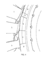
- Fig. 1 shows a perspective view of gas turbine aerofoil blades 1 attached to a rotor disc 7.
- the aerofoil blades 1 have root fixings (not shown) that are slidable into corresponding slots formed in the disc 7.
- Retaining plates 3 are then used to retain the aerofoil blades 1 in attachment to the disc 7.
- the retaining plates 3 themselves are held in place with locking plates 5, which are smaller in circumferential extent than the retaining plates, have a different mass per unit arc, and have a deformed profile for assembly reasons.
- the retaining and locking plates may locate at one side in a grooved rim around the disc and at the other side in a similar grooved rim in the inner platforms of the blades.
- the retaining and locking plates are required to be balanced. Unbalance occurs when a mass centre of a rotor is different from its running centre axis. Units of unbalance are mass times radius. If a mass added to a certain position on a part being balanced shifts the mass centre into the running axis so that the part is in balance, the unbalance unit of the part is the mass of correction multiplied by the applied radius. The retaining and locking plates are thus balanced when the mass centre of the plates coincides with the running centre of the disc.
- a conventional method for balancing a set of retaining/locking plates uses software to distribute the plates into a pattern of even distribution based on the masses of the individual plates. If the unbalance of the complete set of plates is outside certain pre-defined limits, the software swaps the positions of individual masses until the desired result is achieved. Further balancing in a rotating balancing machine may be required to reduce unbalance to within the pre-defined limits.
- a disadvantage of the software method is that it assumes that the plates are evenly circumferentially distributed. Almost invariably, however, this is not the case as the locking plates are usually a different size to the retaining plates. Further, the software method does not take account of the typically different mass per unit arc of the locking plates.
- a first aspect of the present invention provides a method of balancing a set of retaining and locking plates used to retain a row of gas turbine engine aerofoil blades in attachment to a rotor disc, the aerofoil blades having root fixings which are slidable into corresponding slots formed in the disc, the retaining plates being positioned in a circumferential row at a rim of the disc to prevent the root fixings sliding out of the slots, and the locking plates being introduced into the circumferential row between pairs of retaining plates to lock the retaining plates in position, the method including:
- this method can compensate for angular differences between plates, and facilitates their fast and easy balancing.
- a second aspect of the invention provides a method of building a section of a gas turbine engine including:
- the circular track may be defined at one edge by a circular abutment shoulder against which the retaining and locking plates can be located.
- the method may further include measuring cold build expansion gaps formed between the retaining plates when positioned on the track.
- the retaining plates can then be shortened, if necessary, to increase the expansion gaps.
- the retaining plates may have a different mass per unit arc than the locking plates.
- the retaining plates may additionally or alternatively have a different circumferential extent than the locking plates.
- the aerofoil blades may be turbine blades or compressor blades.
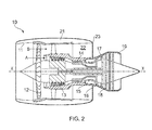
- a ducted fan gas turbine engine is generally indicated at 10 and has a principal and rotational axis X-X.
- the engine comprises, in axial flow series, an air intake 11, a propulsive fan 12, an intermediate pressure compressor 13, a high-pressure compressor 14, combustion equipment 15, a high-pressure turbine 16, an intermediate pressure turbine 17, a low-pressure turbine 18 and a core engine exhaust nozzle 19.
- a nacelle 21 generally surrounds the engine 10 and defines the intake 11, a bypass duct 22 and a bypass exhaust nozzle 23.
- air entering the intake 11 is accelerated by the fan 12 to produce two air flows: a first air flow A into the intermediate pressure compressor 13 and a second air flow B which passes through the bypass duct 22 to provide propulsive thrust.
- the intermediate pressure compressor 13 compresses the air flow A directed into it before delivering that air to the high pressure compressor 14 where further compression takes place.
- the compressed air exhausted from the high-pressure compressor 14 is directed into the combustion equipment 15 where it is mixed with fuel and the mixture combusted.
- the resultant hot combustion products then expand through, and thereby drive the high, intermediate and low-pressure turbines 16, 17, 18 before being exhausted through the nozzle 19 to provide additional propulsive thrust.
- the high, intermediate and low-pressure turbines respectively drive the high and intermediate pressure compressors 14, 13 and the fan 12 by suitable interconnecting shafts.
- retaining 3 and locking 5 plates are used to prevent axial movement of the aerofoil blades of e.g. the high, intermediate and low-pressure turbines 16, 17, 18.
- such plates can be used to retain other types of blades, such as the aerofoil blades of e.g. the intermediate and high-pressure compressors 13, 14.
- the retaining plates 3 are positioned in a circumferential row at a rim of the rotor disc 7 to prevent the root fixings of the blades sliding out of the slots formed in the disc, the radially inner edge of each retaining plate locating in a circular groove formed in the disc, and the radially outer edge of each retaining plate locating in a circular groove formed in the blade platforms.
- the locking plates 5 are introduced into the circumferential row between pairs of retaining plates 3 to lock the retaining plates 3 in position, the inner and outer edges of each locking plate also locating in the aforementioned grooves.
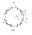
- Fig. 3 shows a weighing plate 109 suitable for use in balancing the set of retaining 3 and locking 5 plates
- Fig. 4 shows a perspective view of the weighing plate 109
- Fig. 5 shows a cross-section view of the weighing plate 109.
- the weighing plate 109 is pancake-shaped and has a circular track 115 (best shown in Fig. 5 ) for receiving the plates.
- the circular track 115 corresponds to the position of the circumferential row of the set of plates 3, 5 in use at the rim of the disc 7, e.g. as illustrated in Fig. 1 .
- the circular track 115 replicates the running radius of the set of plates 3, 5 so that the unbalance of the plates 3, 5 can be determined.
- the circular track 115 may be defined by a circular abutment shoulder 113 which corresponds to the position of the circular groove in which the outer edges of the plates are located in use, as shown in Figs. 4 and 5 . Conveniently, the plates 3, 5 can then be located against the abutment shoulder 113. This simple arrangement facilitates repositioning of the plates 3, 5 into different arrangements.
- the weighing plate 109 is placed on a non-rotating static balancing machine (e.g. a non-rotating vertical balancing machine available from Universal Balancing Ltd), preferably with the centre 111 of the weighing plate 109 (which corresponds to the axis of rotation of the rotor disc 7) located centrally on the machine.
- the machine has instrumentation such that it can detect the unbalance of the plates 3, 5 with respect to the centre 111 of the weighing plate 109.
- Any unbalance in the set of plates 3, 5 located on the circular track 115 is indicated by the balancing machine e.g. by way of a display.
- the unbalance can then be corrected by manually repositioning the plates 3, 5 around the track 115.
- the unbalance may be considered to be corrected and a balanced arrangement achieved when the unbalance falls below a predetermined threshold.
- the threshold can be set so that further balancing in a rotating balancing machine is unnecessary.
- the threshold is typically determined by the unbalance limits of the rotor, which are a function of its mass properties and service speed.
- aerofoil blades 1 are attached to a rotor disc 7 by sliding root fixings of the aerofoil blades into corresponding slots formed in the disc.
- the edges of the retaining 3 and locking 5 plates are then located in their respective grooves in the balanced arrangement at the rim of the disc, to prevent the root fixings sliding out of the slots.
- the locking plates 5 generally have a smaller circumferential extent than the retaining plates 3. Further the locking plates 5 may have a different mass per unit arc.
- the angular difference between the retaining plates 3 and the locking plates 5 is illustrated in Fig. 3 , by the difference between angles A and B. The approach to balancing described above using the circular weighing plate 109 and the non-rotating static balancing machine automatically compensates for this angular difference and for differences in the mass per unit arc of the plates 3, 5.
- the weighing plate 109 can also be used for checking that the retaining plate 3 have sufficient cold build expansion gaps therebetween. If necessary, the circumferential lengths of one or more of the plates 3 can be reduced by machining to increase their respective expansion gaps.
Landscapes
- Engineering & Computer Science (AREA)
- Mechanical Engineering (AREA)
- General Engineering & Computer Science (AREA)
- Turbine Rotor Nozzle Sealing (AREA)
- Testing Of Balance (AREA)
Applications Claiming Priority (1)
| Application Number | Priority Date | Filing Date | Title |
|---|---|---|---|
| GB1308596.4A GB2506712B (en) | 2013-05-14 | 2013-05-14 | Balancing method |
Publications (2)
| Publication Number | Publication Date |
|---|---|
| EP2803867A2 true EP2803867A2 (fr) | 2014-11-19 |
| EP2803867A3 EP2803867A3 (fr) | 2015-06-17 |
Family
ID=48672253
Family Applications (1)
| Application Number | Title | Priority Date | Filing Date |
|---|---|---|---|
| EP14161532.8A Withdrawn EP2803867A3 (fr) | 2013-05-14 | 2014-03-25 | Procédé d'équilibrage |
Country Status (3)
| Country | Link |
|---|---|
| US (1) | US20140338193A1 (fr) |
| EP (1) | EP2803867A3 (fr) |
| GB (1) | GB2506712B (fr) |
Cited By (1)
| Publication number | Priority date | Publication date | Assignee | Title |
|---|---|---|---|---|
| EP4345248A1 (fr) * | 2022-09-30 | 2024-04-03 | Rolls-Royce plc | Masse de simulation d'équilibrage, appareil et procédés associés |
Families Citing this family (5)
| Publication number | Priority date | Publication date | Assignee | Title |
|---|---|---|---|---|
| US10774678B2 (en) | 2017-05-04 | 2020-09-15 | Rolls-Royce Corporation | Turbine assembly with auxiliary wheel |
| US20180320522A1 (en) * | 2017-05-04 | 2018-11-08 | Rolls-Royce Corporation | Turbine assembly with auxiliary wheel |
| US10865646B2 (en) | 2017-05-04 | 2020-12-15 | Rolls-Royce Corporation | Turbine assembly with auxiliary wheel |
| US10968744B2 (en) | 2017-05-04 | 2021-04-06 | Rolls-Royce Corporation | Turbine rotor assembly having a retaining collar for a bayonet mount |
| US10400793B2 (en) * | 2018-01-31 | 2019-09-03 | Asia Vital Components Co., Ltd. | Balance structure of fan |
Family Cites Families (5)
| Publication number | Priority date | Publication date | Assignee | Title |
|---|---|---|---|---|
| GB699582A (en) * | 1950-11-14 | 1953-11-11 | Rolls Royce | Improvements in or relating to gas-turbine engines |
| US5256035A (en) * | 1992-06-01 | 1993-10-26 | United Technologies Corporation | Rotor blade retention and sealing construction |
| GB9302064D0 (en) * | 1993-02-03 | 1993-03-24 | Rolls Royce Plc | Balanced rotor |
| GB9517369D0 (en) * | 1995-08-24 | 1995-10-25 | Rolls Royce Plc | Bladed rotor |
| FR2918106B1 (fr) * | 2007-06-27 | 2011-05-06 | Snecma | Dispositif de retenue axiale d'aubes montees sur un disque de rotor de turbomachine. |
-
2013
- 2013-05-14 GB GB1308596.4A patent/GB2506712B/en not_active Expired - Fee Related
-
2014
- 2014-03-25 US US14/224,721 patent/US20140338193A1/en not_active Abandoned
- 2014-03-25 EP EP14161532.8A patent/EP2803867A3/fr not_active Withdrawn
Cited By (3)
| Publication number | Priority date | Publication date | Assignee | Title |
|---|---|---|---|---|
| EP4345248A1 (fr) * | 2022-09-30 | 2024-04-03 | Rolls-Royce plc | Masse de simulation d'équilibrage, appareil et procédés associés |
| US20240110483A1 (en) * | 2022-09-30 | 2024-04-04 | Rolls-Royce Plc | Balancing simulation mass, apparatus and associated methods |
| US12442301B2 (en) * | 2022-09-30 | 2025-10-14 | Rolls-Royce Plc | Balancing simulation mass, apparatus and associated methods |
Also Published As
| Publication number | Publication date |
|---|---|
| EP2803867A3 (fr) | 2015-06-17 |
| GB201308596D0 (en) | 2013-06-19 |
| GB2506712A (en) | 2014-04-09 |
| GB2506712B (en) | 2018-05-02 |
| US20140338193A1 (en) | 2014-11-20 |
Similar Documents
| Publication | Publication Date | Title |
|---|---|---|
| EP2803867A2 (fr) | Procédé d'équilibrage | |
| EP3049624B1 (fr) | Bague d'équilibrage pour composant rotatif | |
| US9567857B2 (en) | Turbine split ring retention and anti-rotation method | |
| US10145250B2 (en) | Chocking and retaining device | |
| US20150292544A1 (en) | Device for locking a nut | |
| US10436224B2 (en) | Method and apparatus for balancing a rotor | |
| GB2401655A (en) | A rotor blade arrangement | |
| US8429816B2 (en) | Stator ring configuration | |
| EP3170988B1 (fr) | Rotor pour moteur de turbine à gaz | |
| US11053798B2 (en) | Gas turbine engine having a trim balance | |
| US20130280054A1 (en) | Turbine engine stator and method of assembly of the same | |
| US12442301B2 (en) | Balancing simulation mass, apparatus and associated methods | |
| EP3584406B1 (fr) | Équilibrage de pince et de broche pour rotor | |
| US11073031B2 (en) | Blade for a gas turbine engine | |
| US8974185B2 (en) | Balancing of rotatable components | |
| US20180216466A1 (en) | Methods and systems for rotating component balancing | |
| US20130183145A1 (en) | Hybrid inner air seal for gas turbine engines | |
| US20160024946A1 (en) | Rotor blade dovetail with round bearing surfaces | |
| EP3269939A1 (fr) | Ensemble destiné à supporter un anneau et procédé d'assemblage de cet anneau | |
| EP4512994A2 (fr) | Module de rotor et procédé pour mettre à zéro un centre de gravité d'une pluralité d'aubes par rapport à un axe d'un disque de rotor auquel la pluralité d'aubes est fixée | |
| RU2630954C1 (ru) | Способ сборки валопровода | |
| US10001134B2 (en) | Rotor disc |
Legal Events
| Date | Code | Title | Description |
|---|---|---|---|
| PUAI | Public reference made under article 153(3) epc to a published international application that has entered the european phase |
Free format text: ORIGINAL CODE: 0009012 |
|
| 17P | Request for examination filed |
Effective date: 20140325 |
|
| AK | Designated contracting states |
Kind code of ref document: A2 Designated state(s): AL AT BE BG CH CY CZ DE DK EE ES FI FR GB GR HR HU IE IS IT LI LT LU LV MC MK MT NL NO PL PT RO RS SE SI SK SM TR |
|
| AX | Request for extension of the european patent |
Extension state: BA ME |
|
| PUAL | Search report despatched |
Free format text: ORIGINAL CODE: 0009013 |
|
| AK | Designated contracting states |
Kind code of ref document: A3 Designated state(s): AL AT BE BG CH CY CZ DE DK EE ES FI FR GB GR HR HU IE IS IT LI LT LU LV MC MK MT NL NO PL PT RO RS SE SI SK SM TR |
|
| AX | Request for extension of the european patent |
Extension state: BA ME |
|
| RIC1 | Information provided on ipc code assigned before grant |
Ipc: F01D 5/02 20060101ALI20150508BHEP Ipc: F01D 5/30 20060101ALI20150508BHEP Ipc: F04D 29/66 20060101AFI20150508BHEP |
|
| RAP1 | Party data changed (applicant data changed or rights of an application transferred) |
Owner name: ROLLS-ROYCE PLC |
|
| STAA | Information on the status of an ep patent application or granted ep patent |
Free format text: STATUS: THE APPLICATION IS DEEMED TO BE WITHDRAWN |
|
| 18D | Application deemed to be withdrawn |
Effective date: 20151218 |