EP2804247B1 - Procédé de fabrication de batterie secondaire, batterie secondaire et dispositif de soudage - Google Patents
Procédé de fabrication de batterie secondaire, batterie secondaire et dispositif de soudage Download PDFInfo
- Publication number
- EP2804247B1 EP2804247B1 EP13735777.8A EP13735777A EP2804247B1 EP 2804247 B1 EP2804247 B1 EP 2804247B1 EP 13735777 A EP13735777 A EP 13735777A EP 2804247 B1 EP2804247 B1 EP 2804247B1
- Authority
- EP
- European Patent Office
- Prior art keywords
- heat
- resistant
- welding
- separator
- layers
- Prior art date
- Legal status (The legal status is an assumption and is not a legal conclusion. Google has not performed a legal analysis and makes no representation as to the accuracy of the status listed.)
- Active
Links
Images


Classifications
-
- B—PERFORMING OPERATIONS; TRANSPORTING
- B29—WORKING OF PLASTICS; WORKING OF SUBSTANCES IN A PLASTIC STATE IN GENERAL
- B29C—SHAPING OR JOINING OF PLASTICS; SHAPING OF MATERIAL IN A PLASTIC STATE, NOT OTHERWISE PROVIDED FOR; AFTER-TREATMENT OF THE SHAPED PRODUCTS, e.g. REPAIRING
- B29C65/00—Joining or sealing of preformed parts, e.g. welding of plastics materials; Apparatus therefor
- B29C65/02—Joining or sealing of preformed parts, e.g. welding of plastics materials; Apparatus therefor by heating, with or without pressure
- B29C65/08—Joining or sealing of preformed parts, e.g. welding of plastics materials; Apparatus therefor by heating, with or without pressure using ultrasonic vibrations
-
- H—ELECTRICITY
- H01—ELECTRIC ELEMENTS
- H01M—PROCESSES OR MEANS, e.g. BATTERIES, FOR THE DIRECT CONVERSION OF CHEMICAL ENERGY INTO ELECTRICAL ENERGY
- H01M50/00—Constructional details or processes of manufacture of the non-active parts of electrochemical cells other than fuel cells, e.g. hybrid cells
- H01M50/40—Separators; Membranes; Diaphragms; Spacing elements inside cells
- H01M50/46—Separators, membranes or diaphragms characterised by their combination with electrodes
-
- B—PERFORMING OPERATIONS; TRANSPORTING
- B29—WORKING OF PLASTICS; WORKING OF SUBSTANCES IN A PLASTIC STATE IN GENERAL
- B29C—SHAPING OR JOINING OF PLASTICS; SHAPING OF MATERIAL IN A PLASTIC STATE, NOT OTHERWISE PROVIDED FOR; AFTER-TREATMENT OF THE SHAPED PRODUCTS, e.g. REPAIRING
- B29C65/00—Joining or sealing of preformed parts, e.g. welding of plastics materials; Apparatus therefor
- B29C65/56—Joining or sealing of preformed parts, e.g. welding of plastics materials; Apparatus therefor using mechanical means or mechanical connections, e.g. form-fits
-
- B—PERFORMING OPERATIONS; TRANSPORTING
- B29—WORKING OF PLASTICS; WORKING OF SUBSTANCES IN A PLASTIC STATE IN GENERAL
- B29C—SHAPING OR JOINING OF PLASTICS; SHAPING OF MATERIAL IN A PLASTIC STATE, NOT OTHERWISE PROVIDED FOR; AFTER-TREATMENT OF THE SHAPED PRODUCTS, e.g. REPAIRING
- B29C65/00—Joining or sealing of preformed parts, e.g. welding of plastics materials; Apparatus therefor
- B29C65/82—Testing the joint
- B29C65/8207—Testing the joint by mechanical methods
- B29C65/8215—Tensile tests
-
- B—PERFORMING OPERATIONS; TRANSPORTING
- B29—WORKING OF PLASTICS; WORKING OF SUBSTANCES IN A PLASTIC STATE IN GENERAL
- B29C—SHAPING OR JOINING OF PLASTICS; SHAPING OF MATERIAL IN A PLASTIC STATE, NOT OTHERWISE PROVIDED FOR; AFTER-TREATMENT OF THE SHAPED PRODUCTS, e.g. REPAIRING
- B29C65/00—Joining or sealing of preformed parts, e.g. welding of plastics materials; Apparatus therefor
- B29C65/82—Testing the joint
- B29C65/8207—Testing the joint by mechanical methods
- B29C65/8223—Peel tests
-
- B—PERFORMING OPERATIONS; TRANSPORTING
- B29—WORKING OF PLASTICS; WORKING OF SUBSTANCES IN A PLASTIC STATE IN GENERAL
- B29C—SHAPING OR JOINING OF PLASTICS; SHAPING OF MATERIAL IN A PLASTIC STATE, NOT OTHERWISE PROVIDED FOR; AFTER-TREATMENT OF THE SHAPED PRODUCTS, e.g. REPAIRING
- B29C66/00—General aspects of processes or apparatus for joining preformed parts
- B29C66/01—General aspects dealing with the joint area or with the area to be joined
- B29C66/05—Particular design of joint configurations
- B29C66/10—Particular design of joint configurations particular design of the joint cross-sections
- B29C66/11—Joint cross-sections comprising a single joint-segment, i.e. one of the parts to be joined comprising a single joint-segment in the joint cross-section
- B29C66/112—Single lapped joints
- B29C66/1122—Single lap to lap joints, i.e. overlap joints
-
- B—PERFORMING OPERATIONS; TRANSPORTING
- B29—WORKING OF PLASTICS; WORKING OF SUBSTANCES IN A PLASTIC STATE IN GENERAL
- B29C—SHAPING OR JOINING OF PLASTICS; SHAPING OF MATERIAL IN A PLASTIC STATE, NOT OTHERWISE PROVIDED FOR; AFTER-TREATMENT OF THE SHAPED PRODUCTS, e.g. REPAIRING
- B29C66/00—General aspects of processes or apparatus for joining preformed parts
- B29C66/01—General aspects dealing with the joint area or with the area to be joined
- B29C66/05—Particular design of joint configurations
- B29C66/20—Particular design of joint configurations particular design of the joint lines, e.g. of the weld lines
- B29C66/21—Particular design of joint configurations particular design of the joint lines, e.g. of the weld lines said joint lines being formed by a single dot or dash or by several dots or dashes, i.e. spot joining or spot welding
-
- B—PERFORMING OPERATIONS; TRANSPORTING
- B29—WORKING OF PLASTICS; WORKING OF SUBSTANCES IN A PLASTIC STATE IN GENERAL
- B29C—SHAPING OR JOINING OF PLASTICS; SHAPING OF MATERIAL IN A PLASTIC STATE, NOT OTHERWISE PROVIDED FOR; AFTER-TREATMENT OF THE SHAPED PRODUCTS, e.g. REPAIRING
- B29C66/00—General aspects of processes or apparatus for joining preformed parts
- B29C66/01—General aspects dealing with the joint area or with the area to be joined
- B29C66/05—Particular design of joint configurations
- B29C66/304—Joining through openings in an intermediate part of the article
-
- B—PERFORMING OPERATIONS; TRANSPORTING
- B29—WORKING OF PLASTICS; WORKING OF SUBSTANCES IN A PLASTIC STATE IN GENERAL
- B29C—SHAPING OR JOINING OF PLASTICS; SHAPING OF MATERIAL IN A PLASTIC STATE, NOT OTHERWISE PROVIDED FOR; AFTER-TREATMENT OF THE SHAPED PRODUCTS, e.g. REPAIRING
- B29C66/00—General aspects of processes or apparatus for joining preformed parts
- B29C66/40—General aspects of joining substantially flat articles, e.g. plates, sheets or web-like materials; Making flat seams in tubular or hollow articles; Joining single elements to substantially flat surfaces
- B29C66/41—Joining substantially flat articles ; Making flat seams in tubular or hollow articles
- B29C66/43—Joining a relatively small portion of the surface of said articles
-
- B—PERFORMING OPERATIONS; TRANSPORTING
- B29—WORKING OF PLASTICS; WORKING OF SUBSTANCES IN A PLASTIC STATE IN GENERAL
- B29C—SHAPING OR JOINING OF PLASTICS; SHAPING OF MATERIAL IN A PLASTIC STATE, NOT OTHERWISE PROVIDED FOR; AFTER-TREATMENT OF THE SHAPED PRODUCTS, e.g. REPAIRING
- B29C66/00—General aspects of processes or apparatus for joining preformed parts
- B29C66/40—General aspects of joining substantially flat articles, e.g. plates, sheets or web-like materials; Making flat seams in tubular or hollow articles; Joining single elements to substantially flat surfaces
- B29C66/41—Joining substantially flat articles ; Making flat seams in tubular or hollow articles
- B29C66/43—Joining a relatively small portion of the surface of said articles
- B29C66/433—Casing-in, i.e. enclosing an element between two sheets by an outlined seam
-
- B—PERFORMING OPERATIONS; TRANSPORTING
- B29—WORKING OF PLASTICS; WORKING OF SUBSTANCES IN A PLASTIC STATE IN GENERAL
- B29C—SHAPING OR JOINING OF PLASTICS; SHAPING OF MATERIAL IN A PLASTIC STATE, NOT OTHERWISE PROVIDED FOR; AFTER-TREATMENT OF THE SHAPED PRODUCTS, e.g. REPAIRING
- B29C66/00—General aspects of processes or apparatus for joining preformed parts
- B29C66/70—General aspects of processes or apparatus for joining preformed parts characterised by the composition, physical properties or the structure of the material of the parts to be joined; Joining with non-plastics material
- B29C66/71—General aspects of processes or apparatus for joining preformed parts characterised by the composition, physical properties or the structure of the material of the parts to be joined; Joining with non-plastics material characterised by the composition of the plastics material of the parts to be joined
-
- B—PERFORMING OPERATIONS; TRANSPORTING
- B29—WORKING OF PLASTICS; WORKING OF SUBSTANCES IN A PLASTIC STATE IN GENERAL
- B29C—SHAPING OR JOINING OF PLASTICS; SHAPING OF MATERIAL IN A PLASTIC STATE, NOT OTHERWISE PROVIDED FOR; AFTER-TREATMENT OF THE SHAPED PRODUCTS, e.g. REPAIRING
- B29C66/00—General aspects of processes or apparatus for joining preformed parts
- B29C66/70—General aspects of processes or apparatus for joining preformed parts characterised by the composition, physical properties or the structure of the material of the parts to be joined; Joining with non-plastics material
- B29C66/72—General aspects of processes or apparatus for joining preformed parts characterised by the composition, physical properties or the structure of the material of the parts to be joined; Joining with non-plastics material characterised by the structure of the material of the parts to be joined
- B29C66/723—General aspects of processes or apparatus for joining preformed parts characterised by the composition, physical properties or the structure of the material of the parts to be joined; Joining with non-plastics material characterised by the structure of the material of the parts to be joined being multi-layered
- B29C66/7232—General aspects of processes or apparatus for joining preformed parts characterised by the composition, physical properties or the structure of the material of the parts to be joined; Joining with non-plastics material characterised by the structure of the material of the parts to be joined being multi-layered comprising a non-plastics layer
- B29C66/72324—General aspects of processes or apparatus for joining preformed parts characterised by the composition, physical properties or the structure of the material of the parts to be joined; Joining with non-plastics material characterised by the structure of the material of the parts to be joined being multi-layered comprising a non-plastics layer consisting of inorganic materials not provided for in B29C66/72321 - B29C66/72322
- B29C66/72325—Ceramics
-
- B—PERFORMING OPERATIONS; TRANSPORTING
- B29—WORKING OF PLASTICS; WORKING OF SUBSTANCES IN A PLASTIC STATE IN GENERAL
- B29C—SHAPING OR JOINING OF PLASTICS; SHAPING OF MATERIAL IN A PLASTIC STATE, NOT OTHERWISE PROVIDED FOR; AFTER-TREATMENT OF THE SHAPED PRODUCTS, e.g. REPAIRING
- B29C66/00—General aspects of processes or apparatus for joining preformed parts
- B29C66/70—General aspects of processes or apparatus for joining preformed parts characterised by the composition, physical properties or the structure of the material of the parts to be joined; Joining with non-plastics material
- B29C66/72—General aspects of processes or apparatus for joining preformed parts characterised by the composition, physical properties or the structure of the material of the parts to be joined; Joining with non-plastics material characterised by the structure of the material of the parts to be joined
- B29C66/727—General aspects of processes or apparatus for joining preformed parts characterised by the composition, physical properties or the structure of the material of the parts to be joined; Joining with non-plastics material characterised by the structure of the material of the parts to be joined being porous, e.g. foam
-
- B—PERFORMING OPERATIONS; TRANSPORTING
- B29—WORKING OF PLASTICS; WORKING OF SUBSTANCES IN A PLASTIC STATE IN GENERAL
- B29C—SHAPING OR JOINING OF PLASTICS; SHAPING OF MATERIAL IN A PLASTIC STATE, NOT OTHERWISE PROVIDED FOR; AFTER-TREATMENT OF THE SHAPED PRODUCTS, e.g. REPAIRING
- B29C66/00—General aspects of processes or apparatus for joining preformed parts
- B29C66/70—General aspects of processes or apparatus for joining preformed parts characterised by the composition, physical properties or the structure of the material of the parts to be joined; Joining with non-plastics material
- B29C66/73—General aspects of processes or apparatus for joining preformed parts characterised by the composition, physical properties or the structure of the material of the parts to be joined; Joining with non-plastics material characterised by the intensive physical properties of the material of the parts to be joined, by the optical properties of the material of the parts to be joined, by the extensive physical properties of the parts to be joined, by the state of the material of the parts to be joined or by the material of the parts to be joined being a thermoplastic or a thermoset
- B29C66/731—General aspects of processes or apparatus for joining preformed parts characterised by the composition, physical properties or the structure of the material of the parts to be joined; Joining with non-plastics material characterised by the intensive physical properties of the material of the parts to be joined, by the optical properties of the material of the parts to be joined, by the extensive physical properties of the parts to be joined, by the state of the material of the parts to be joined or by the material of the parts to be joined being a thermoplastic or a thermoset characterised by the intensive physical properties of the material of the parts to be joined
- B29C66/7311—Thermal properties
-
- B—PERFORMING OPERATIONS; TRANSPORTING
- B29—WORKING OF PLASTICS; WORKING OF SUBSTANCES IN A PLASTIC STATE IN GENERAL
- B29C—SHAPING OR JOINING OF PLASTICS; SHAPING OF MATERIAL IN A PLASTIC STATE, NOT OTHERWISE PROVIDED FOR; AFTER-TREATMENT OF THE SHAPED PRODUCTS, e.g. REPAIRING
- B29C66/00—General aspects of processes or apparatus for joining preformed parts
- B29C66/70—General aspects of processes or apparatus for joining preformed parts characterised by the composition, physical properties or the structure of the material of the parts to be joined; Joining with non-plastics material
- B29C66/73—General aspects of processes or apparatus for joining preformed parts characterised by the composition, physical properties or the structure of the material of the parts to be joined; Joining with non-plastics material characterised by the intensive physical properties of the material of the parts to be joined, by the optical properties of the material of the parts to be joined, by the extensive physical properties of the parts to be joined, by the state of the material of the parts to be joined or by the material of the parts to be joined being a thermoplastic or a thermoset
- B29C66/731—General aspects of processes or apparatus for joining preformed parts characterised by the composition, physical properties or the structure of the material of the parts to be joined; Joining with non-plastics material characterised by the intensive physical properties of the material of the parts to be joined, by the optical properties of the material of the parts to be joined, by the extensive physical properties of the parts to be joined, by the state of the material of the parts to be joined or by the material of the parts to be joined being a thermoplastic or a thermoset characterised by the intensive physical properties of the material of the parts to be joined
- B29C66/7311—Thermal properties
- B29C66/73113—Thermal conductivity
-
- B—PERFORMING OPERATIONS; TRANSPORTING
- B29—WORKING OF PLASTICS; WORKING OF SUBSTANCES IN A PLASTIC STATE IN GENERAL
- B29C—SHAPING OR JOINING OF PLASTICS; SHAPING OF MATERIAL IN A PLASTIC STATE, NOT OTHERWISE PROVIDED FOR; AFTER-TREATMENT OF THE SHAPED PRODUCTS, e.g. REPAIRING
- B29C66/00—General aspects of processes or apparatus for joining preformed parts
- B29C66/80—General aspects of machine operations or constructions and parts thereof
- B29C66/81—General aspects of the pressing elements, i.e. the elements applying pressure on the parts to be joined in the area to be joined, e.g. the welding jaws or clamps
- B29C66/814—General aspects of the pressing elements, i.e. the elements applying pressure on the parts to be joined in the area to be joined, e.g. the welding jaws or clamps characterised by the design of the pressing elements, e.g. of the welding jaws or clamps
- B29C66/8141—General aspects of the pressing elements, i.e. the elements applying pressure on the parts to be joined in the area to be joined, e.g. the welding jaws or clamps characterised by the design of the pressing elements, e.g. of the welding jaws or clamps characterised by the surface geometry of the part of the pressing elements, e.g. welding jaws or clamps, coming into contact with the parts to be joined
- B29C66/81411—General aspects of the pressing elements, i.e. the elements applying pressure on the parts to be joined in the area to be joined, e.g. the welding jaws or clamps characterised by the design of the pressing elements, e.g. of the welding jaws or clamps characterised by the surface geometry of the part of the pressing elements, e.g. welding jaws or clamps, coming into contact with the parts to be joined characterised by its cross-section, e.g. transversal or longitudinal, being non-flat
- B29C66/81421—General aspects of the pressing elements, i.e. the elements applying pressure on the parts to be joined in the area to be joined, e.g. the welding jaws or clamps characterised by the design of the pressing elements, e.g. of the welding jaws or clamps characterised by the surface geometry of the part of the pressing elements, e.g. welding jaws or clamps, coming into contact with the parts to be joined characterised by its cross-section, e.g. transversal or longitudinal, being non-flat being convex or concave
- B29C66/81422—General aspects of the pressing elements, i.e. the elements applying pressure on the parts to be joined in the area to be joined, e.g. the welding jaws or clamps characterised by the design of the pressing elements, e.g. of the welding jaws or clamps characterised by the surface geometry of the part of the pressing elements, e.g. welding jaws or clamps, coming into contact with the parts to be joined characterised by its cross-section, e.g. transversal or longitudinal, being non-flat being convex or concave being convex
-
- B—PERFORMING OPERATIONS; TRANSPORTING
- B29—WORKING OF PLASTICS; WORKING OF SUBSTANCES IN A PLASTIC STATE IN GENERAL
- B29C—SHAPING OR JOINING OF PLASTICS; SHAPING OF MATERIAL IN A PLASTIC STATE, NOT OTHERWISE PROVIDED FOR; AFTER-TREATMENT OF THE SHAPED PRODUCTS, e.g. REPAIRING
- B29C66/00—General aspects of processes or apparatus for joining preformed parts
- B29C66/80—General aspects of machine operations or constructions and parts thereof
- B29C66/81—General aspects of the pressing elements, i.e. the elements applying pressure on the parts to be joined in the area to be joined, e.g. the welding jaws or clamps
- B29C66/814—General aspects of the pressing elements, i.e. the elements applying pressure on the parts to be joined in the area to be joined, e.g. the welding jaws or clamps characterised by the design of the pressing elements, e.g. of the welding jaws or clamps
- B29C66/8141—General aspects of the pressing elements, i.e. the elements applying pressure on the parts to be joined in the area to be joined, e.g. the welding jaws or clamps characterised by the design of the pressing elements, e.g. of the welding jaws or clamps characterised by the surface geometry of the part of the pressing elements, e.g. welding jaws or clamps, coming into contact with the parts to be joined
- B29C66/81427—General aspects of the pressing elements, i.e. the elements applying pressure on the parts to be joined in the area to be joined, e.g. the welding jaws or clamps characterised by the design of the pressing elements, e.g. of the welding jaws or clamps characterised by the surface geometry of the part of the pressing elements, e.g. welding jaws or clamps, coming into contact with the parts to be joined comprising a single ridge, e.g. for making a weakening line; comprising a single tooth
- B29C66/81429—General aspects of the pressing elements, i.e. the elements applying pressure on the parts to be joined in the area to be joined, e.g. the welding jaws or clamps characterised by the design of the pressing elements, e.g. of the welding jaws or clamps characterised by the surface geometry of the part of the pressing elements, e.g. welding jaws or clamps, coming into contact with the parts to be joined comprising a single ridge, e.g. for making a weakening line; comprising a single tooth comprising a single tooth
-
- B—PERFORMING OPERATIONS; TRANSPORTING
- B29—WORKING OF PLASTICS; WORKING OF SUBSTANCES IN A PLASTIC STATE IN GENERAL
- B29C—SHAPING OR JOINING OF PLASTICS; SHAPING OF MATERIAL IN A PLASTIC STATE, NOT OTHERWISE PROVIDED FOR; AFTER-TREATMENT OF THE SHAPED PRODUCTS, e.g. REPAIRING
- B29C66/00—General aspects of processes or apparatus for joining preformed parts
- B29C66/80—General aspects of machine operations or constructions and parts thereof
- B29C66/81—General aspects of the pressing elements, i.e. the elements applying pressure on the parts to be joined in the area to be joined, e.g. the welding jaws or clamps
- B29C66/814—General aspects of the pressing elements, i.e. the elements applying pressure on the parts to be joined in the area to be joined, e.g. the welding jaws or clamps characterised by the design of the pressing elements, e.g. of the welding jaws or clamps
- B29C66/8141—General aspects of the pressing elements, i.e. the elements applying pressure on the parts to be joined in the area to be joined, e.g. the welding jaws or clamps characterised by the design of the pressing elements, e.g. of the welding jaws or clamps characterised by the surface geometry of the part of the pressing elements, e.g. welding jaws or clamps, coming into contact with the parts to be joined
- B29C66/81433—General aspects of the pressing elements, i.e. the elements applying pressure on the parts to be joined in the area to be joined, e.g. the welding jaws or clamps characterised by the design of the pressing elements, e.g. of the welding jaws or clamps characterised by the surface geometry of the part of the pressing elements, e.g. welding jaws or clamps, coming into contact with the parts to be joined being toothed, i.e. comprising several teeth or pins, or being patterned
-
- B—PERFORMING OPERATIONS; TRANSPORTING
- B29—WORKING OF PLASTICS; WORKING OF SUBSTANCES IN A PLASTIC STATE IN GENERAL
- B29C—SHAPING OR JOINING OF PLASTICS; SHAPING OF MATERIAL IN A PLASTIC STATE, NOT OTHERWISE PROVIDED FOR; AFTER-TREATMENT OF THE SHAPED PRODUCTS, e.g. REPAIRING
- B29C66/00—General aspects of processes or apparatus for joining preformed parts
- B29C66/80—General aspects of machine operations or constructions and parts thereof
- B29C66/83—General aspects of machine operations or constructions and parts thereof characterised by the movement of the joining or pressing tools
- B29C66/832—Reciprocating joining or pressing tools
- B29C66/8322—Joining or pressing tools reciprocating along one axis
-
- H—ELECTRICITY
- H01—ELECTRIC ELEMENTS
- H01M—PROCESSES OR MEANS, e.g. BATTERIES, FOR THE DIRECT CONVERSION OF CHEMICAL ENERGY INTO ELECTRICAL ENERGY
- H01M10/00—Secondary cells; Manufacture thereof
- H01M10/04—Construction or manufacture in general
- H01M10/0404—Machines for assembling batteries
-
- H—ELECTRICITY
- H01—ELECTRIC ELEMENTS
- H01M—PROCESSES OR MEANS, e.g. BATTERIES, FOR THE DIRECT CONVERSION OF CHEMICAL ENERGY INTO ELECTRICAL ENERGY
- H01M10/00—Secondary cells; Manufacture thereof
- H01M10/04—Construction or manufacture in general
- H01M10/0436—Small-sized flat cells or batteries for portable equipment
-
- H—ELECTRICITY
- H01—ELECTRIC ELEMENTS
- H01M—PROCESSES OR MEANS, e.g. BATTERIES, FOR THE DIRECT CONVERSION OF CHEMICAL ENERGY INTO ELECTRICAL ENERGY
- H01M10/00—Secondary cells; Manufacture thereof
- H01M10/05—Accumulators with non-aqueous electrolyte
- H01M10/052—Li-accumulators
- H01M10/0525—Rocking-chair batteries, i.e. batteries with lithium insertion or intercalation in both electrodes; Lithium-ion batteries
-
- H—ELECTRICITY
- H01—ELECTRIC ELEMENTS
- H01M—PROCESSES OR MEANS, e.g. BATTERIES, FOR THE DIRECT CONVERSION OF CHEMICAL ENERGY INTO ELECTRICAL ENERGY
- H01M10/00—Secondary cells; Manufacture thereof
- H01M10/05—Accumulators with non-aqueous electrolyte
- H01M10/058—Construction or manufacture
-
- H—ELECTRICITY
- H01—ELECTRIC ELEMENTS
- H01M—PROCESSES OR MEANS, e.g. BATTERIES, FOR THE DIRECT CONVERSION OF CHEMICAL ENERGY INTO ELECTRICAL ENERGY
- H01M10/00—Secondary cells; Manufacture thereof
- H01M10/05—Accumulators with non-aqueous electrolyte
- H01M10/058—Construction or manufacture
- H01M10/0585—Construction or manufacture of accumulators having only flat construction elements, i.e. flat positive electrodes, flat negative electrodes and flat separators
-
- H—ELECTRICITY
- H01—ELECTRIC ELEMENTS
- H01M—PROCESSES OR MEANS, e.g. BATTERIES, FOR THE DIRECT CONVERSION OF CHEMICAL ENERGY INTO ELECTRICAL ENERGY
- H01M50/00—Constructional details or processes of manufacture of the non-active parts of electrochemical cells other than fuel cells, e.g. hybrid cells
- H01M50/10—Primary casings; Jackets or wrappings
-
- H—ELECTRICITY
- H01—ELECTRIC ELEMENTS
- H01M—PROCESSES OR MEANS, e.g. BATTERIES, FOR THE DIRECT CONVERSION OF CHEMICAL ENERGY INTO ELECTRICAL ENERGY
- H01M50/00—Constructional details or processes of manufacture of the non-active parts of electrochemical cells other than fuel cells, e.g. hybrid cells
- H01M50/10—Primary casings; Jackets or wrappings
- H01M50/102—Primary casings; Jackets or wrappings characterised by their shape or physical structure
- H01M50/105—Pouches or flexible bags
-
- H—ELECTRICITY
- H01—ELECTRIC ELEMENTS
- H01M—PROCESSES OR MEANS, e.g. BATTERIES, FOR THE DIRECT CONVERSION OF CHEMICAL ENERGY INTO ELECTRICAL ENERGY
- H01M50/00—Constructional details or processes of manufacture of the non-active parts of electrochemical cells other than fuel cells, e.g. hybrid cells
- H01M50/10—Primary casings; Jackets or wrappings
- H01M50/116—Primary casings; Jackets or wrappings characterised by the material
-
- H—ELECTRICITY
- H01—ELECTRIC ELEMENTS
- H01M—PROCESSES OR MEANS, e.g. BATTERIES, FOR THE DIRECT CONVERSION OF CHEMICAL ENERGY INTO ELECTRICAL ENERGY
- H01M50/00—Constructional details or processes of manufacture of the non-active parts of electrochemical cells other than fuel cells, e.g. hybrid cells
- H01M50/10—Primary casings; Jackets or wrappings
- H01M50/116—Primary casings; Jackets or wrappings characterised by the material
- H01M50/117—Inorganic material
- H01M50/119—Metals
-
- H—ELECTRICITY
- H01—ELECTRIC ELEMENTS
- H01M—PROCESSES OR MEANS, e.g. BATTERIES, FOR THE DIRECT CONVERSION OF CHEMICAL ENERGY INTO ELECTRICAL ENERGY
- H01M50/00—Constructional details or processes of manufacture of the non-active parts of electrochemical cells other than fuel cells, e.g. hybrid cells
- H01M50/10—Primary casings; Jackets or wrappings
- H01M50/116—Primary casings; Jackets or wrappings characterised by the material
- H01M50/121—Organic material
-
- H—ELECTRICITY
- H01—ELECTRIC ELEMENTS
- H01M—PROCESSES OR MEANS, e.g. BATTERIES, FOR THE DIRECT CONVERSION OF CHEMICAL ENERGY INTO ELECTRICAL ENERGY
- H01M50/00—Constructional details or processes of manufacture of the non-active parts of electrochemical cells other than fuel cells, e.g. hybrid cells
- H01M50/10—Primary casings; Jackets or wrappings
- H01M50/116—Primary casings; Jackets or wrappings characterised by the material
- H01M50/124—Primary casings; Jackets or wrappings characterised by the material having a layered structure
- H01M50/126—Primary casings; Jackets or wrappings characterised by the material having a layered structure comprising three or more layers
-
- H—ELECTRICITY
- H01—ELECTRIC ELEMENTS
- H01M—PROCESSES OR MEANS, e.g. BATTERIES, FOR THE DIRECT CONVERSION OF CHEMICAL ENERGY INTO ELECTRICAL ENERGY
- H01M50/00—Constructional details or processes of manufacture of the non-active parts of electrochemical cells other than fuel cells, e.g. hybrid cells
- H01M50/40—Separators; Membranes; Diaphragms; Spacing elements inside cells
- H01M50/409—Separators, membranes or diaphragms characterised by the material
-
- H—ELECTRICITY
- H01—ELECTRIC ELEMENTS
- H01M—PROCESSES OR MEANS, e.g. BATTERIES, FOR THE DIRECT CONVERSION OF CHEMICAL ENERGY INTO ELECTRICAL ENERGY
- H01M50/00—Constructional details or processes of manufacture of the non-active parts of electrochemical cells other than fuel cells, e.g. hybrid cells
- H01M50/40—Separators; Membranes; Diaphragms; Spacing elements inside cells
- H01M50/409—Separators, membranes or diaphragms characterised by the material
- H01M50/449—Separators, membranes or diaphragms characterised by the material having a layered structure
- H01M50/451—Separators, membranes or diaphragms characterised by the material having a layered structure comprising layers of only organic material and layers containing inorganic material
-
- B—PERFORMING OPERATIONS; TRANSPORTING
- B29—WORKING OF PLASTICS; WORKING OF SUBSTANCES IN A PLASTIC STATE IN GENERAL
- B29L—INDEXING SCHEME ASSOCIATED WITH SUBCLASS B29C, RELATING TO PARTICULAR ARTICLES
- B29L2031/00—Other particular articles
- B29L2031/34—Electrical apparatus, e.g. sparking plugs or parts thereof
- B29L2031/3468—Batteries, accumulators or fuel cells
-
- H—ELECTRICITY
- H01—ELECTRIC ELEMENTS
- H01M—PROCESSES OR MEANS, e.g. BATTERIES, FOR THE DIRECT CONVERSION OF CHEMICAL ENERGY INTO ELECTRICAL ENERGY
- H01M50/00—Constructional details or processes of manufacture of the non-active parts of electrochemical cells other than fuel cells, e.g. hybrid cells
- H01M50/10—Primary casings; Jackets or wrappings
- H01M50/116—Primary casings; Jackets or wrappings characterised by the material
- H01M50/124—Primary casings; Jackets or wrappings characterised by the material having a layered structure
-
- H—ELECTRICITY
- H01—ELECTRIC ELEMENTS
- H01M—PROCESSES OR MEANS, e.g. BATTERIES, FOR THE DIRECT CONVERSION OF CHEMICAL ENERGY INTO ELECTRICAL ENERGY
- H01M50/00—Constructional details or processes of manufacture of the non-active parts of electrochemical cells other than fuel cells, e.g. hybrid cells
- H01M50/50—Current conducting connections for cells or batteries
- H01M50/543—Terminals
- H01M50/547—Terminals characterised by the disposition of the terminals on the cells
- H01M50/55—Terminals characterised by the disposition of the terminals on the cells on the same side of the cell
-
- H—ELECTRICITY
- H01—ELECTRIC ELEMENTS
- H01M—PROCESSES OR MEANS, e.g. BATTERIES, FOR THE DIRECT CONVERSION OF CHEMICAL ENERGY INTO ELECTRICAL ENERGY
- H01M50/00—Constructional details or processes of manufacture of the non-active parts of electrochemical cells other than fuel cells, e.g. hybrid cells
- H01M50/50—Current conducting connections for cells or batteries
- H01M50/543—Terminals
- H01M50/552—Terminals characterised by their shape
- H01M50/553—Terminals adapted for prismatic, pouch or rectangular cells
- H01M50/557—Plate-shaped terminals
-
- Y—GENERAL TAGGING OF NEW TECHNOLOGICAL DEVELOPMENTS; GENERAL TAGGING OF CROSS-SECTIONAL TECHNOLOGIES SPANNING OVER SEVERAL SECTIONS OF THE IPC; TECHNICAL SUBJECTS COVERED BY FORMER USPC CROSS-REFERENCE ART COLLECTIONS [XRACs] AND DIGESTS
- Y02—TECHNOLOGIES OR APPLICATIONS FOR MITIGATION OR ADAPTATION AGAINST CLIMATE CHANGE
- Y02E—REDUCTION OF GREENHOUSE GAS [GHG] EMISSIONS, RELATED TO ENERGY GENERATION, TRANSMISSION OR DISTRIBUTION
- Y02E60/00—Enabling technologies; Technologies with a potential or indirect contribution to GHG emissions mitigation
- Y02E60/10—Energy storage using batteries
-
- Y—GENERAL TAGGING OF NEW TECHNOLOGICAL DEVELOPMENTS; GENERAL TAGGING OF CROSS-SECTIONAL TECHNOLOGIES SPANNING OVER SEVERAL SECTIONS OF THE IPC; TECHNICAL SUBJECTS COVERED BY FORMER USPC CROSS-REFERENCE ART COLLECTIONS [XRACs] AND DIGESTS
- Y02—TECHNOLOGIES OR APPLICATIONS FOR MITIGATION OR ADAPTATION AGAINST CLIMATE CHANGE
- Y02P—CLIMATE CHANGE MITIGATION TECHNOLOGIES IN THE PRODUCTION OR PROCESSING OF GOODS
- Y02P70/00—Climate change mitigation technologies in the production process for final industrial or consumer products
- Y02P70/50—Manufacturing or production processes characterised by the final manufactured product
Definitions
- the present invention relates to a secondary battery manufacturing method, a secondary battery, and a welding apparatus thereof.
- Patent Literature 1 Japanese Patent Publication No. 3584583
- This secondary battery employs a separator whose face opposing to an electrode (e.g. a positive electrode) is provided with a heat-resistant layer.
- the positive electrode, the heat-resistant-layer-provided separator, and a negative electrode are laminated on one another in this order.
- Patent Literature 2 Another secondary battery is disclosed in Japanese Unexamined Patent Application Publication No. 2004-158344 (Patent Literature 2). To prevent a separator from moving inside the secondary battery, this related art holds an end of the separator between sheaths and welds the separator and sheaths together to fix them. Ultrasonic welding techniques are known from US2011/0036480 and EP2399723 .
- the heat-resistant-layer-provided separator of the Patent Literature 1 is used with the sheaths of the Patent Literature 2 to hold and weld an end of the separator between the sheaths.
- the heat-resistant layer is strong against heat and does not melt at a temperature that may be sufficient to thermally weld the resin sheaths and separator to each other.
- using the heat-resistant-layer-provided separator has a problem that an end of the separator and the sheaths are hardly welded or fixed together.
- the present invention provides a secondary battery manufacturing method capable of manufacturing a secondary battery that includes resin separators provided with heat-resistant layers and capable of surely welding the separators and sheaths together, or the separators themselves together.
- the present invention also provides a secondary battery in which heat-resistant-layer-provided separators and sheaths, or the heat-resistant-layer-provided separators themselves are surely fixed together. Further, the present invention provides a welding apparatus capable of surely welding heat-resistant-layer-provided separators and sheaths together, or the heat-resistant-layer-provided separators themselves together.
- the secondary battery manufacturing method includes employing a welding jig that has a pressure vibrator, a jig receiver arranged at a position opposing to the pressure vibrator, and projections formed on both the pressure vibrator and jig receiver.
- the method holds and pressurizes in a laminated direction and vibrates a welding part having a structure in which a plurality of separator layers made of resin and heat-resistant layers interposed among the separator layers are laminated on one another.
- the pressurization and vibration break the heat-resistant layers in the welding part and weld together the resin of the separator layers that joins together in the broken part.
- the secondary battery is manufactured according to the above-mentioned secondary battery manufacturing method and includes sheaths each having a resin layer on the surface thereof and a power generation element covered with the sheaths.
- the power generation element includes a lamination of a positive electrode, a negative electrode, and a heat-resistant-layered separator interposed between the positive and negative electrodes. A part of an end of the separator is held between peripheral parts of the sheaths. The heat-resistant layer positioned at the part held between the sheaths is broken so that, at the broken part, the resin layers of the sheaths and resin of the separator weld together.
- the secondary battery is formed according to the above-mentioned secondary battery manufacturing method and includes a bagged electrode having one of positive and negative electrodes between two heat-resistant-layered separators that are formed into a bag.
- the heat-resistant layers are broken at a part of an area where the separators overlap, and at the broken part, the resin of the separators welds together.
- the welding apparatus includes a welding jig having a pressure vibrator, a jig receiver positioned to face the pressure vibrator, and projections arranged on both the pressure vibrator and jig receiver and an ultrasonic vibrator to vibrate at least the pressure vibrator.
- the pressure vibrator and jig receiver hold and pressurize in a laminated direction and vibrate a welding part having a structure in which a plurality of separator layers of resin and heat-resistant layers interposed among the separator layers are laminated on one another, thereby breaking the heat-resistant layers in the welding part and welding together the resin of the separator layers that joins together in the broken part.
- the entire front end of each of the projections is shaped into a circular arc.
- a secondary battery according to the embodiment will be explained, and thereafter, a welding apparatus for manufacturing the secondary battery, a secondary battery manufacturing method employing the welding apparatus, and a bagged electrode manufacturing method will be explained.
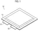
- Figure 1 is a perspective view illustrating the exterior of a secondary battery according to an embodiment.
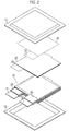
- Figure 2 is an exploded perspective view of the secondary battery according to the present embodiment.
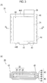
- Figure 3 is an explanatory view illustrating a bagged positive electrode (bagged electrode) adopted in the secondary battery according to the present embodiment, in which Fig. 3(A) is a plan view and Fig. 3(B) is a sectional view along a line B-B of Fig. 3(A) .
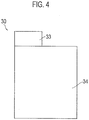
- Figure 4 is a plan view of a negative electrode adopted in the secondary battery according to the present embodiment.
- Figure 5 is a view explaining an internal structure of the secondary battery according to the present embodiment, in which Fig.
- Fig. 5(A) is a sectional view explaining an essential part of the internal structure of the secondary battery according to the present embodiment and Fig. 5(B) is an enlarged sectional view of an engaging part at an end of the secondary battery illustrated in Fig. 5(A) .
- the secondary battery 10 has, as illustrated in Fig. 1 , a flat square shape.
- a positive electrode lead 11 and a negative electrode lead 12 are led out from the same end of sheaths 13.
- the sheaths 13 contain a power generation element 15 that achieves charge and discharge reactions.
- the power generation element 15 is formed with, as illustrated in Fig. 2 , bagged positive electrodes 20 and negative electrodes 30 that are alternately stacked on each other.
- the bagged positive electrode 20 has, as illustrated in Fig. 3 , two separators provided with heat-resistant layer 40 that are joined together along edges thereof into a bag to contain a positive electrode 22. Between the positive electrode 22 and a separator layer 48 made of resin, there is a heat-resistant layer 49.
- the separator layer 48 and heat-resistant layers 49 form a three-layer structure made by coating each face of the resin separator with ceramics (heat-resistant material) serving as the heat-resistant layer 49.
- the material formed by coating each face of the separator layer with the heat-resistant layer is referred to as the separator provided with heat-resistant layer 40.
- the separator layer 48 is made of polyolefin-based porous resin such as polyethylene and polypropylene.
- the positive electrode 22 has a rectangular shape and includes a very thin sheet-like positive electrode collector (collecting foil) 21 and a positive electrode active material layer 24 formed on each face of the positive electrode collector 21.
- the positive electrode active material layer 24 is extended over the positive electrode 22 except for a positive electrode tab 23.
- the two separators with heat-resistant layer 40 are joined together at each end part, i.e., joining part 42 into a bag. Accordingly, the two separators with heat-resistant layer 40 each are larger than the positive electrode 22 (except for the positive electrode tab 23). A manufacturing method of the bagged positive electrode 20 will be explained later.
- the positive electrode tab 23 is pulled out, and on a side 44B opposite to the side 44A, a partly protruding engaging part 43 is formed.
- the engaging part 43 engages with the sheaths 13 within the sheaths 13, thereby fixing the power generation element 15 to the sheaths 13.
- the negative electrode 30 has, as illustrated in Fig. 4 , a rectangular shape and includes a very thin sheet-like negative electrode collector (collecting foil) 31 and a negative electrode active material layer 34 formed on each face of the negative electrode collector 31.
- the negative electrode active material layer 34 is extended over the negative electrode 30 except for a negative electrode tab 33.
- the power generation element 15 includes the negative electrodes 30 and bagged positive electrodes 20 that are alternately stacked on one another. This forms a laminated structure illustrated in Fig. 5 in which the heat-resistant-layer-provided separator 40 is interposed between the negative electrode 30 and the positive electrode 22. At an end part illustrated in Fig. 5(A) , the sheaths 13 are sealed with the engaging parts 43 of the heat-resistant-layered separators 40 held between the sheaths 13. In the stacked state, the positive electrode tabs 23 and negative electrode tabs 33 are connected to the positive electrode lead 11 and negative electrode lead 12, respectively (refer to Fig. 2 ). In Fig. 5 , the separator layer 48 and heat-resistant layers 49 of each heat-resistant-layered separator 40 are omitted.
- the negative electrode active material layer 34 is larger by one size in a plan view than the positive electrode active material layer 24 of the positive electrode 22.
- FIG. 5(A) is an enlarged sectional view of the engaging part 43.
- the sheath 13 is, for example, a laminated sheet.
- the laminated sheet 13 includes a metal base material 50 and a resin layer 51 coated over each face of the base material 50. Sealing the sheaths 13 is usually carried out by thermal welding.
- the resin layer 51 of each laminated sheet melts when heat is applied thereto to weld overlapping portions together. This is the same as the related art (Patent Literature 2). If the separator has no heat-resistant layer, the sheaths 13 and the end part of each separator held between the sheaths 13 are heated so that the resin of the separators and the resin layers 51 of the sheaths 13 melt and weld together.
- the resin melts at a temperature of about 130 to 180 degrees centigrade.
- the heat-resistant layer 49 is made of, for example, porous ceramics, that may pass an electrolyte but, as the name suggests, is resistive against heat and does not melt at the temperature of about 130 to 180 degrees centigrade.
- the heat-resistant layer 49 is porous, and therefore, has a small thermal conductivity and good thermal insulation properties.
- a heat-resistant temperature of the heat-resistant layer is, for example, 800 degrees centigrade or greater.
- the embodiment pressurizes and vibrates a part (welding part) of the sheaths 13 where the engaging part 43 of each heat-resistant-layered separator 40 is held, to break the heat-resistant layers 49 and weld the welding part.
- a method of manufacturing a lithium ion secondary battery by alternately laminating the bagged positive electrodes 20 and negative electrodes 30 of the embodiment is a generally known method, and therefore, is not explained in more detail.
- Materials such as positive electrode active material, negative electrode active material, collecting foils, and the like used for making the lithium ion secondary battery are standard materials, and therefore, are not explained.
- the apparatus is referred to as an ultrasonic welding apparatus because it applies ultrasonic vibration while welding.
- Figure 6 is a schematic view explaining the ultrasonic welding apparatus according to an embodiment of the present invention, in which Fig. 6(A) is a plan view and Fig. 6(B) is a side view seen from the direction of an arrow B of Fig. 6(A) .
- the ultrasonic welding apparatus 100 has a stage 101 for placing a work thereon, a pressure vibrator 111 that is vertically movable on the stage 101, a jig receiver 112 that is positioned opposite to the pressure vibrator 111, and an ultrasonic vibrator 130 that vibrates the pressure vibrator 111.
- the pressure vibrator 111 and jig receiver 112 are collectively referred to as a welding jig 110.
- the work includes the power generation element 15, which contains the bagged positive electrodes 20 and negative electrodes 30 laminated on each other, and the sheaths 13 that hold the power generation element 15 from each laminated-direction end.
- the work is a secondary battery before sealing the sheaths 13.
- the pressure vibrator 111 moves around the work and thermally welds the sheaths 13 made of resin.
- the pressure vibrator 111 is provided with the ultrasonic vibrator 130 for vibrating the pressure vibrator 111.
- a contact face of the pressure vibrator 111 is an irregular face 125 having projections 121.
- Figure 7 is a view illustrating the work contact face 125 of the pressure vibrator 111, in which Fig. 7(A) is a plan view, Fig. 7(B) is a side view seen from the direction of an arrow B of Fig. 7(A), and Fig. 7(C) is a side view seen from the direction of an arrow C of Fig. 7(A) .
- the work contact face 125 of the pressure vibrator 111 is the irregular face 125 having a plurality of projections 121.
- a front end of each projection 121 is shaped into a circular arc. As will be explained later, roundness at the front end of each projection 121 removes broken part of the heat-resistant layer 49 so that the separator layer 48 made of resin may easily come into contact with another.
- the circular arc shape functions not to injure the surface of the sheath 13 when vibrating.
- each projection 121 may properly be set according to the thickness of the part (welding part) to weld.
- the height may be equal to or greater than the thickness of the stacked part.
- the height of the projection 121 must be equal to or greater than the thickness of the welding part and must be easy to manufacture (fabricate). The height may be sufficient if it is about twice as large as the thickness of the welding part.
- the chamfering of the projection 121 is dependent on the dimensions and height thereof.
- the chamfering must be sized so that, when pressurizing, the projection 121 pushes off broken part of the heat-resistant layers.
- the separator layer 48 is made of resin and is flexible, and therefore, fragments (crushed fragments) created when the hard heat-resistant layer 49 is broken are pushed along the roundness of the projection 121 toward the periphery of the projection 121 where pressurizing force is relatively small. Taking such action into consideration, the chamfering quantity of the projection 121 is determined.
- the heat-resistant-layered separators 40 and the two sheaths 13 that hold the separators 40 between them have a total thickness of, for example, 700 micrometers. To weld this, it is preferable that the chamfering quantity of the projection 121 is about 1 to 2 millimeters.
- the overall size (the size of the work contact part) of the pressure vibrator 111 is set not to break the electrodes contained in the sheaths 13 when welding a peripheral part of the sheaths 13. For this, the pressure vibrator 111 must be smaller than a distance from an edge of the electrodes in the sheaths 13 to an edge of the sheaths 13. It is acceptable if the pressure vibrator 111 protrudes from the edge of the sheaths 13.
- the pressure vibrator 111 is movable on the stage 101. Namely, the pressure vibrator 111 and work move relative to each other on the stage 101 along the periphery of the sheath 13 and the peripheries of the sheaths 13 are sealed together.
- the jig receiver 112 is arranged at a position opposing to the pressure vibrator 111.
- the surface of the jig receiver 112 is an irregular face having projections 121 positioned to face the projections 121 of the pressure vibrator 111.
- the dimensions and height of each projection 121 of the jig receiver 112 are similar to those of the projection 121 of the pressure vibrator 111. Namely, it is sufficient if the height of the projection 121 is higher than the thickness of the welding part. It is sufficient if the jig receiver 112 is positioned to face the pressure vibrator 111.
- the pressure vibrator 111 may be moved and the jig receiver 112 may be arranged entirely along the locus of the pressure vibrator 111.
- the jig receiver 112 may be configured to move together with the pressure vibrator 111.
- the work is fixed to the stage 101 and around which the pressure vibrator 111 and jig receiver 112 are moved together.
- the work fixed to the stage 101 may be moved between the pressure vibrator 111 and the jig receiver 112 that are fixed.
- the welding part is set to protrude from the stage and the periphery of the protruding part is held and welded by the pressure vibrator 111 and jig receiver 112.
- the ultrasonic vibrator 130 vibrates at least the contact face of the pressure vibrator 111 that is in contact with the work. Vibrating directions are a direction (horizontal direction) along the surface of the work and a direction (vertical direction) in which the work is pressurized.
- the ultrasonic vibrator 130 may be an ultrasonic vibration apparatus used for, for example, ultrasonic welding. According to the embodiment, the ultrasonic vibrator conducts two-direction vibration as mentioned above. A vibration frequency and a vibration amplitude are set to break the heat-resistant layer by pressurization and vibration and melt the resin with frictional heat produced by the vibration.
- the ultrasonic welding apparatus 100 having such a structure is also used to weld overlapping parts of the two heat-resistant-layered separators 40 outside the electrode (the positive electrode 22 in the present embodiment) when manufacturing the bagged electrode 20 (refer to the welding parts 42 of Fig. 3 ).
- the thickness of the welding part (the part to be welded) is different from that of the case of welding the separators 40 and sheaths 13 together. Accordingly, the height of each projection 121 and the chamfering quantity thereof are changed according to the welding part.
- the welding part of the bagged electrode 20 to be manufactured includes only the two heat-resistant-layered separators 40 that are laid on each other.
- the thickness of one heat-resistant-layered separator 40 is only about 20 to 30 micrometers. Accordingly, the welding part has a thickness of about 40 to 60 micrometers. Therefore, the height of the projection 121 is sufficient if it is equal to or greater than 20 micrometers. Namely, the height of the projection 121 of each of the pressure vibrator 111 and jig receiver 112 is 20 micrometers or greater, i.e., 40 micrometers or greater in total. An upper limit is not particularly set in this case, and therefore, the height is determined so as to realize easy manufacturing. It is sufficient if the upper limit height of the projection 121 of each of the pressure vibrator 111 and jig receiver 112 is set to about twice as large as the thickness of the two heat-resistant-layered separators 40 that are laid on each other.
- the chamfering quantity may be small because the projection 121 is small and heat-resistant layer fragments to be removed are thin and small.
- the chamfering quantity is preferably about 0.1 to 1 millimeters in curvature radius.
- the pressure vibrator 111 is configured to have an overall size (the size of the part in contact with a work) not to harm the electrode held between the two heat-resistant-layered separators 40 that are going to be formed into a bag.
- the size is set to be smaller than the distance from an edge of the electrode to an edge of the two heat-resistant-layered separators 40. There will be no problem if the pressure vibrator 111 protrudes from the edge of the two heat-resistant-layer-provided separators 40.
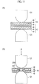
- Figure 8 is an enlarged sectional view illustrating a state that a work is held with the welding jig 110 of the ultrasonic welding apparatus 100, in which Fig. 8(A) is an enlarged sectional view illustrating an essential part before pressurization and vibration and Fig. 8(B) is an enlarged sectional view illustrating the essential part after the pressurization and vibration.
- the part illustrated in Fig. 8 shows a pair of the projections 121 (one is of the pressure vibrator 111 and the other is of the jig receiver 112) that hold and pressurize the two sheaths 13 and the engaging parts 43 of a plurality of the heat-resistant-layered separators 40 held between the sheaths 13.
- the embodiment sets the part to be welded (welding part) of the work between the pressure vibrator 111 and jig receiver 112 of the ultrasonic welding apparatus 100.
- the part to be welded (welding part) of the work is a part where the engaging parts 43 of the heat-resistant-layered separators 40 are held between the two sheaths 13.
- the pressure vibrator 111 is lowered to pressurize the welding part (an arrow P of the drawing). Simultaneously with the pressurization, the ultrasonic vibrator 130 vibrates the pressure vibrator 111. As a result, the heat-resistant layers are pressed from each side of the sheaths, and at the same time, are vibrated.
- the pressurization and vibration break the laminated heat-resistant layers 49 in the very small pressurized area up to the central heat-resistant layers 49 in the laminated direction.
- the projections 121 push fragments 210 of the broken heat-resistant layers 49 toward the peripheries thereof.
- the part (broken part 200) where the heat-resistant layers 49 are broken allows the separator layers 48 to come into contact with each other. Due to the vibration at this time, the sheaths 13, heat-resistant-layered separators 40, and the like in the pressurized area rub one another to generate heat that melts the resin layers 51 of the sheaths 13 and the resin of the separator layers 48 and weld them together. Around the welded part, there are fragments 210 of the heat-resistant layers 49.
- This sort of welding action differs from a welding action of general ultrasonic welding.
- the general ultrasonic welding welds, for example, two metal plates or resin materials to each other by applying vibration with a horn of an ultrasonic welding apparatus so that the two metal plates or resin materials rub each other. Friction at this time generates heat, and at the rubbed part, molecules join together to achieve welding.
- the vibration applied according to the present invention acts, as mentioned above, to break the heat-resistant layers 49.
- friction due to the vibration and pressurization are not intended to promote the joining of molecules at the welding part.
- the heat generated by friction caused by vibration according to the present embodiment does not act by itself to weld frictional faces to each other.
- the frictional heat of the embodiment only works to melt the resin. This point also differs from the general ultrasonic welding.
- Tests were conducted by holding a lamination of heat-resistant-layered separators between sheaths.
- the thickness of a welding part (including the sheaths and heat-resistant-layered separators) before welding was 700 micrometers.
- Welding was carried out with the pressure vibrator 111 having the projections 121 each having the same height as the thickness of the welding part.
- a plurality of samples were welded and subjected to a peeling test.
- the peeling test was conducted as illustrated in Fig. 9 by chucking not-welded (not joined) ends of the sheaths 13 and pulling them away from each other.
- Figure 10 is a graph illustrating a result of the peeling test.
- An abscissa indicates tensile strength and an ordinate occurrence frequency.
- a to D are samples formed according to the present embodiment and E is a sample thermally welded without vibration with a jig whose work contact face is flat.
- the samples A to D formed according to the present embodiment are higher in tensile strength than the sample E formed without vibration.
- a bagged electrode manufacturing method employing the above-mentioned ultrasonic welding apparatus 100 will be explained. Although the manufacturing of a bagged electrode is included in the secondary battery manufacturing method, it is possible to separately carry out the manufacturing of a bagged electrode.
- Figure 11 is an enlarged sectional view illustrating a state that a work is held with the welding jig of the ultrasonic welding apparatus 100, in which Fig. 11(A) is an enlarged sectional view illustrating an essential part before pressurization and vibration and Fig. 11(B) is an enlarged sectional view illustrating the essential part after the pressurization and vibration.
- the part illustrated in Fig. 11 includes two heat-resistant-layered separators 40 laid on each other and projections 121 that pressurize the part in question.
- the embodiment sets a part to be welded (welding part) of the work between the pressure vibrator 111 and jig receiver 112 of the ultrasonic welding apparatus 100.
- the part to be welded (welding part) of the work is a part where the two heat-resistant-layered separators 40 are stacked on each other.
- the pressure vibrator 111 is lowered to pressurize the welding part (an arrow P of the drawing). Simultaneously with the pressurization, the ultrasonic vibrator 130 vibrates the pressure vibrator 111. As a result, inner heat-resistant layers are pressed from each side of the heat-resistant-layered separators, and at the same time, are vibrated. The pressurization and vibration break, in the very small pressurized area, the heat-resistant layers 49 of the heat-resistant-layered separators 40. Due to the pressurization at this time, the projections 121 push fragments 201 of the broken heat-resistant layers 49 toward the peripheries.
- the part (broken part 201) where the heat-resistant layers 49 are broken allows the separator layers 48 to come into contact with each other. Due to the vibration at this time, the heat-resistant-layer-provided separators 40 in the pressurized area rub each other to generate heat that melts resin of the separator layers 48 and weld (join) them together. Namely, the heat generated in the rubbing flat area transmits to the separator layers 48 to produce a high temperature to melt and weld the resin.
- This sort of welding action is the same as that of the above-mentioned secondary battery manufacturing method.
- the thickness of a welding part (a total of the two heat-resistant-layered separators) before welding was 50 micrometers.
- Welding was carried out with the pressure vibrator 111 having the projections 121 each having the same height as the thickness of the welding part.
- the projection 121 had a cylindrical shape of 0.5 millimeters in diameter.
- a plurality of samples were welded and subjected to a peeling test.
- the peeling test was conducted like that illustrated in Fig. 9 by chucking not-welded (not joined) ends of the two heat-resistant-layered separators 40 and by pulling them away from each other.
- Table 1 illustrates a result of the test. It was examined if a tensile strength with respect to an ultrasonic vibration time was equal to or greater than a predetermined value.
- the tensile strength is OK if it is about the same as that obtained when thermally welding separators having no heat-resistant layers (with a jig that applies only heat but no vibration and has a flat contact face to a work), LOW if it is lower than that, and HIGH if it is higher than that. OK and HIGH indicate sufficient weld strength.
- the amplitude is a relative movement with respect to a 100% movement (i.e., a movement of 0.5 millimeters) corresponding to the entire projection 121. Vibration directions were horizontal and vertical (with the same amplitude).
- the bagged positive electrode 20 explained above as an example of a bagged electrode contains the positive electrode 22.
- the electrode contained in the bagged electrode may be the negative electrode 30.
- the heat-resistant-layered separator 40 has a three layer structure including the heat-resistant layer 49, separator layer 48, and heat-resistant layer 49. Instead, it may have a two-layer structure including the separator layer 48 and the heat-resistant layer 49 formed only on one face of the separator layer 48.
- a role of the heat-resistant layer 49 is, as explained already, to prevent direct connection between the positive electrode 22 and the negative electrode 30 even if an internal short circuit occurs to generate heat that melts the separator layer 48.
- the heat-resistant-layered separators 40 of two-layer structure each having the heat-resistant layer 49 only on one face of the separator layer 48 are used to pack the positive electrode 22 (or the negative electrode 30) and when the pack is laid on the negative electrode 30 (or the positive electrode 22), the heat-resistant layer 49 is always present between the positive electrode 22 and the negative electrode 30. Accordingly, the heat-resistant-layered separator 40 of two-layer structure, can play the role of the heat-resistant layer 49.
- they are joined (welded) at each joining part 42 so that the heat-resistant layer comes between the two separator layers 48.
- the two heat-resistant-layered separators of two-layer structure 40 are arranged so that the heat-resistant layer 49 of at least one of them faces the electrode.
- the heat-resistant layer 49 is formed on each face of the separator layer 48 made of resin.
- the heat-resistant layer 49 arranged between the separator layer 48 and the electrode is a heat-resistant material that is coated in advance onto a separator material.
- the separator layer 48 and heat-resistant layer 49 may be discrete materials.
- a heat generator such as an electric heater or an induction heater
- a contact face between the welding jig and a work may be employed.
- the secondary battery explained in each of the embodiments is a lithium ion secondary battery
- the present invention is not limited to the lithium ion secondary battery but is applicable to various types of secondary batteries.
- the present invention pressurizes and vibrates a welding part having a laminated structure in which a plurality of separator layers made of resin and heat-resistant layers are alternately laminated on each other.
- the pressurization and vibration break the heat-resistant layers in the welding part so that the resin of the separator layers in the broken part joins, melts, and welds together due to frictional heat generated by the vibration. This results in surely welding the welding part including the heat-resistant layers.
Landscapes
- Engineering & Computer Science (AREA)
- Mechanical Engineering (AREA)
- Chemical & Material Sciences (AREA)
- Electrochemistry (AREA)
- General Chemical & Material Sciences (AREA)
- Chemical Kinetics & Catalysis (AREA)
- Manufacturing & Machinery (AREA)
- Inorganic Chemistry (AREA)
- Physics & Mathematics (AREA)
- Thermal Sciences (AREA)
- Ceramic Engineering (AREA)
- Materials Engineering (AREA)
- Secondary Cells (AREA)
- Cell Separators (AREA)
- Sealing Battery Cases Or Jackets (AREA)
Claims (7)
- Procédé de fabrication de batterie secondaire comprenant le fait
d'utiliser un gabarit de soudage (110) qui a un vibrateur par pression (111), un récepteur de gabarit (112) agencé à une position opposée au vibrateur par pression (111), et des saillies (121) formées sur le vibrateur par pression (111) et le récepteur de gabarit (112) et
d'amener le vibrateur par pression (111) à maintenir et à mettre sous pression dans une direction stratifiée et à faire vibrer une partie de soudage ayant une structure où une pluralité de couches de séparation (48) de résine et de couches résistant à la chaleur (49) interposées entre les couches de séparation (48) sont stratifiées les unes sur les autres, rompant ainsi les couches résistant à la chaleur (49) dans la partie de soudage et soudant ensemble les résines des couches de séparation (48) qui se rejoignent dans la partie rompue,
dans lequel une extrémité avant entière de chacune des saillies (121) est conformée en un arc de cercle. - Procédé de fabrication de batterie secondaire selon la revendication 1, dans lequel les saillies (121) sont agencées aux deux positions opposées sur le vibrateur par pression et le récepteur de gabarit.
- Procédé de fabrication de batterie secondaire selon l'une quelconque des revendications 1 ou 2, dans lequel :la partie de soudage comporte en outre une gaine (13) qui a une couche de résine (51) au-dessus de la surface de celle-ci et est agencée à chaque extrémité dans la direction stratifiée de la partie ; etla pluralité de couches de séparation (48) de résine et les couches résistant à la chaleur (49) sont stratifiées les unes sur les autres et le vibrateur par pression (111) et le récepteur de gabarit (112) maintiennent, mettent sous pression, et font vibrer chaque gaine à partir d'une face de la gaine (13) qui se trouve sur un côté externe dans la direction stratifiée.
- Procédé de fabrication de batterie secondaire selon l'une quelconque des revendications 1 ou 2, dans lequel
la partie de soudage est une partie ayant une stratification de la pluralité de séparateurs à couches résistant à la chaleur (40) comportant une pluralité de couches de séparation (48) et de couches résistant à la chaleur (49) revêtues sur chaque face de chaque couche de séparation, et
le vibrateur par pression (111) et le récepteur de gabarit (112) maintiennent, mettent sous pression, et font vibrer la stratification des séparateurs à couches résistant à la chaleur (40) à partir de chaque côté externe dans la direction stratifiée. - Batterie secondaire fabriquée selon le procédé de fabrication de batterie secondaire selon la revendication 3, comprenant en outre :des gaines (13) ayant chacune une couche de résine (51) sur la surface de celle-ci ; etun élément de génération de puissance (15) recouvert des gaines (13), oùl'élément de génération de puissance (15) comporte une électrode positive (20) et une électrode négative (30) qui sont stratifiées l'une sur l'autre avec un séparateur à couches résistant à la chaleur (40) interposé entre elles, une partie d'une extrémité du séparateur (40) est maintenue entre les gaines (13) à une partie de la périphérie des gaines, une couche résistant à la chaleur (49) du séparateur à la partie maintenue est rompue, et les couches de résine (51) des gaines et de la résine du séparateur (40) sont soudées ensemble à la partie rompue.
- Batterie secondaire fabriquée selon le procédé de fabrication de batterie secondaire selon la revendication 4, comprenant en outre :une électrode ensachée comportant l'une parmi les électrodes positive et négative (20, 30) entre deux séparateurs à couches résistant à la chaleur (40) formés à l'intérieur d'un sac, dans lequeldes couches résistant à la chaleur (49) des séparateurs positionnés à une partie d'une zone où les séparateurs à couches résistant à la chaleur (40) en frome de sac sont placés les uns sur les autres à l'extérieur de l'électrode maintenue entre les séparateurs sont rompues de sorte que les résines des séparateurs à la partie rompue soient soudées ensemble.
- Appareil de soudage comprenant :un gabarit de soudage (110) ayant un vibrateur par pression (111), un récepteur de gabarit (112) positionné pour faire face au vibrateur par pression (111), et des saillies (121) agencées sur le vibrateur par pression (111) et le récepteur de gabarit (112) ; etun vibrateur à ultrasons (130) faisant vibrer au moins le vibrateur par pression (111), dans lequelle vibrateur par pression (111) et le récepteur de gabarit (112) maintiennent et mettent sous pression dans une direction stratifiée et font vibrer une partie de soudage ayant une structure où une pluralité de couches de séparation (48) de résine et de couches résistant à la chaleur (49) interposées entre les couches de séparation (48) sont stratifiées les unes sur les autres, rompant ainsi les couches résistant à la chaleur (49) dans la partie de soudage et soudant ensemble les résines des couches de séparation (48) qui se rejoignent dans la partie rompue,dans lequel une extrémité avant entière de chacune des saillies (121) est conformée en un arc de cercle.
Applications Claiming Priority (2)
| Application Number | Priority Date | Filing Date | Title |
|---|---|---|---|
| JP2012004215A JP5899938B2 (ja) | 2012-01-12 | 2012-01-12 | 二次電池の製造方法、二次電池 |
| PCT/JP2013/050374 WO2013105630A1 (fr) | 2012-01-12 | 2013-01-11 | Procédé de fabrication de batterie secondaire, batterie secondaire et dispositif de dépôt |
Publications (3)
| Publication Number | Publication Date |
|---|---|
| EP2804247A1 EP2804247A1 (fr) | 2014-11-19 |
| EP2804247A4 EP2804247A4 (fr) | 2015-06-03 |
| EP2804247B1 true EP2804247B1 (fr) | 2018-08-08 |
Family
ID=48781572
Family Applications (1)
| Application Number | Title | Priority Date | Filing Date |
|---|---|---|---|
| EP13735777.8A Active EP2804247B1 (fr) | 2012-01-12 | 2013-01-11 | Procédé de fabrication de batterie secondaire, batterie secondaire et dispositif de soudage |
Country Status (6)
| Country | Link |
|---|---|
| US (1) | US9620755B2 (fr) |
| EP (1) | EP2804247B1 (fr) |
| JP (1) | JP5899938B2 (fr) |
| KR (1) | KR101618488B1 (fr) |
| TW (1) | TWI479716B (fr) |
| WO (1) | WO2013105630A1 (fr) |
Families Citing this family (38)
| Publication number | Priority date | Publication date | Assignee | Title |
|---|---|---|---|---|
| JP5939133B2 (ja) * | 2012-05-23 | 2016-06-22 | 株式会社豊田自動織機 | 電極を収納済みのセパレータ、蓄電装置、及び電極を収納済みのセパレータの製造方法 |
| EP2940775B1 (fr) * | 2012-12-28 | 2019-03-27 | Nissan Motor Co., Ltd | Éléctrode et procédé pour souder un séparateur sur l'éléctrode |
| WO2015050084A1 (fr) * | 2013-10-02 | 2015-04-09 | 日産自動車株式会社 | Procédé pour lier des séparateurs dans un dispositif électrique, appareil pour lier des séparateurs dans un dispositif électrique et dispositif électrique |
| US9793571B2 (en) | 2013-10-03 | 2017-10-17 | Nissan Motor Co., Ltd. | Apparatus for bonding separators in electrical devices |
| JP6361108B2 (ja) * | 2013-10-24 | 2018-07-25 | 日産自動車株式会社 | 電気デバイスのセパレータ接合方法および電気デバイスのセパレータ接合装置 |
| JP6343905B2 (ja) * | 2013-10-24 | 2018-06-20 | 日産自動車株式会社 | 電気デバイスのセパレータ接合方法および電気デバイスのセパレータ接合装置 |
| JP2017027652A (ja) * | 2013-12-05 | 2017-02-02 | 日立マクセル株式会社 | 非水電解質二次電池及びその製造方法 |
| JP6427909B2 (ja) * | 2014-03-24 | 2018-11-28 | 日産自動車株式会社 | 電気デバイスのセパレータ接合装置 |
| WO2016002059A1 (fr) | 2014-07-03 | 2016-01-07 | 日産自動車株式会社 | Procédé de collage de matériaux composites et dispositif de collage de matériaux composites |
| KR101720387B1 (ko) * | 2014-08-04 | 2017-03-27 | 주식회사 엘지화학 | 전극조립체, 전지셀 및 전지셀 제조방법 |
| USD768076S1 (en) * | 2015-01-13 | 2016-10-04 | Lg Chem, Ltd. | Battery for portable terminal |
| USD768074S1 (en) * | 2015-01-13 | 2016-10-04 | Lg Chem, Ltd. | Battery for portable terminal |
| USD788030S1 (en) * | 2015-01-13 | 2017-05-30 | Lg Chem, Ltd. | Battery for portable terminal |
| USD768568S1 (en) * | 2015-01-13 | 2016-10-11 | Lg Chem, Ltd. | Battery for portable terminal |
| USD777664S1 (en) * | 2015-01-13 | 2017-01-31 | Lg Chem, Ltd. | Battery for portable terminal |
| USD768075S1 (en) * | 2015-01-13 | 2016-10-04 | Lg Chem, Ltd. | Battery for portable terminal |
| KR102504793B1 (ko) * | 2015-11-23 | 2023-02-27 | 삼성에스디아이 주식회사 | 이차전지 |
| WO2017110842A1 (fr) * | 2015-12-25 | 2017-06-29 | 日立マクセル株式会社 | Batterie rechargeable à électrolyte non aqueux et procédé permettant de fabriquer cette dernière |
| WO2018043406A1 (fr) * | 2016-08-29 | 2018-03-08 | リチウム エナジー アンド パワー ゲゼルシャフト ミット ベシュレンクテル ハフッング ウント コンパニー コマンディトゲゼルシャフト | Corps d'électrode stratifié et élément de stockage d'électricité |
| CN110114909B (zh) | 2016-08-29 | 2022-03-29 | 株式会社杰士汤浅国际 | 间隔件的超声波熔接方法 |
| DE112017004317T5 (de) * | 2016-08-29 | 2019-05-16 | Gs Yuasa International Ltd. | Laminierter Elektrodenkörper und ein elektrisches Speicherelement |
| KR102174607B1 (ko) * | 2016-09-09 | 2020-11-05 | 주식회사 엘지화학 | 실링 돌기를 포함하는 전지케이스용 프리 실링 장치 및 이를 사용하여 전지셀을 제조하는 방법 |
| BE1024231B1 (nl) | 2016-10-18 | 2017-12-20 | Resilux N.V. | Sonotrode en aambeeld voor het ultrasoon lassen van kunststoffen, werkwijze voor het produceren van een kunststofbehouder |
| KR102029718B1 (ko) * | 2017-01-19 | 2019-10-08 | 주식회사 엘지화학 | 전지케이스의 수납부 크기에 따라 변형되는 구조의 지그 |
| JP2018120803A (ja) * | 2017-01-27 | 2018-08-02 | 日産自動車株式会社 | フィルム外装電池の製造方法およびフィルム外装電池 |
| JP6917736B2 (ja) * | 2017-03-09 | 2021-08-11 | 株式会社Gsユアサ | セパレータの超音波溶着方法 |
| JP2018152226A (ja) | 2017-03-13 | 2018-09-27 | リチウム エナジー アンド パワー ゲゼルシャフト ミット ベシュレンクテル ハフッング ウント コンパニー コマンディトゲゼルシャフトLithium Energy and Power GmbH & Co. KG | 袋詰正極板、積層電極体、蓄電素子及び袋詰正極板の製造方法 |
| JP2019016494A (ja) * | 2017-07-06 | 2019-01-31 | リチウム エナジー アンド パワー ゲゼルシャフト ミット ベシュレンクテル ハフッング ウント コンパニー コマンディトゲゼルシャフトLithium Energy and Power GmbH & Co. KG | 積層電極体の製造方法及び蓄電素子の製造方法 |
| JP2019016493A (ja) * | 2017-07-06 | 2019-01-31 | リチウム エナジー アンド パワー ゲゼルシャフト ミット ベシュレンクテル ハフッング ウント コンパニー コマンディトゲゼルシャフトLithium Energy and Power GmbH & Co. KG | 電極体のサブユニット、電極ユニット、積層電極体及び蓄電素子 |
| JP6984233B2 (ja) * | 2017-08-25 | 2021-12-17 | 株式会社豊田自動織機 | 蓄電モジュールの製造方法及び蓄電モジュールの製造装置 |
| JP6977396B2 (ja) * | 2017-08-25 | 2021-12-08 | 株式会社豊田自動織機 | 蓄電モジュールの製造方法及び蓄電モジュールの製造装置 |
| JP7244431B2 (ja) * | 2017-10-25 | 2023-03-22 | 株式会社エンビジョンAescジャパン | セパレータ、袋状セパレータ、袋詰電極およびリチウムイオン二次電池 |
| DE102018201293A1 (de) | 2018-01-29 | 2019-08-01 | Gs Yuasa International Ltd. | Ultraschall-Schweißverfahren |
| JP6996421B2 (ja) | 2018-05-28 | 2022-02-21 | 大日本印刷株式会社 | 電池、ヒートシール装置、及び電池の製造方法 |
| EP4201651A4 (fr) * | 2020-10-12 | 2024-04-10 | LG Energy Solution, Ltd. | Appareil de scellement d'un boîtier de batterie et batterie secondaire fabriquée à l'aide de celui-ci |
| EP4087003A3 (fr) * | 2021-05-05 | 2022-12-14 | DarmokTech | Cellule, batterie au lithium et procédé de démontage de la batterie |
| US12199253B2 (en) * | 2021-11-05 | 2025-01-14 | GM Global Technology Operations LLC | Laminated thermal barrier for anisotropic heat transfer |
| EP4385652A4 (fr) * | 2022-05-31 | 2025-10-15 | Lg Energy Solution Ltd | Dispositif de soudage au laser et procédé de soudage l'utilisant |
Family Cites Families (16)
| Publication number | Priority date | Publication date | Assignee | Title |
|---|---|---|---|---|
| JPH06103628B2 (ja) * | 1986-02-14 | 1994-12-14 | 松下電器産業株式会社 | 鉛蓄電池 |
| JP3168686B2 (ja) * | 1992-04-07 | 2001-05-21 | 日本電池株式会社 | アルカリ二次電池およびその製造方法 |
| JPH0679784A (ja) * | 1992-09-03 | 1994-03-22 | Mitsubishi Plastics Ind Ltd | プラスチツクフイルムの超音波溶着方法 |
| US5605771A (en) * | 1995-10-26 | 1997-02-25 | Zbb Technologies, Inc. | Component design for an electric energy storing device |
| JP3584583B2 (ja) | 1995-12-12 | 2004-11-04 | ソニー株式会社 | 積層型非水電解液二次電池 |
| GB9801983D0 (en) * | 1998-01-30 | 1998-03-25 | Young Michael J R | Welding polymer fabrics using ultrasound |
| DE10123309A1 (de) * | 2001-05-14 | 2002-12-05 | Imtex S L | Verfahren zum Verbinden von Stücken aus textilem Gewebe |
| JP4135474B2 (ja) * | 2002-11-07 | 2008-08-20 | 日産自動車株式会社 | ラミネート二次電池、複数のラミネート二次電池からなる組電池モジュール、複数の組電池モジュールからなる組電池ならびにこれらいずれかの電池を搭載した電気自動車 |
| JP3754420B2 (ja) | 2003-02-04 | 2006-03-15 | 三洋電機株式会社 | 二次電池用電極板及びその製造方法並びにこの電極板を用いた二次電池 |
| JP2005183594A (ja) * | 2003-12-18 | 2005-07-07 | Japan Vilene Co Ltd | 非水系電気化学素子 |
| US20110036480A1 (en) * | 2007-07-11 | 2011-02-17 | Elag Verpackungen Ag | Method of joining films |
| JP2010143156A (ja) * | 2008-12-20 | 2010-07-01 | Fujita Kikai:Kk | 超音波溶着法 |
| KR101124327B1 (ko) | 2009-02-19 | 2012-03-15 | 주식회사티움리서치 | 리튬전지 및 그 제조방법 |
| KR101290223B1 (ko) * | 2010-03-09 | 2013-07-30 | 히다치 막셀 가부시키가이샤 | 편평형 전지 |
| EP2399723A1 (fr) * | 2010-06-24 | 2011-12-28 | Amcor Flexibles Kreuzlingen Ltd. | Récipient d'emballage |
| JP5613512B2 (ja) * | 2010-09-27 | 2014-10-22 | 株式会社クラレ | 熱可塑性液晶ポリマーフィルム融着物の製造方法 |
-
2012
- 2012-01-12 JP JP2012004215A patent/JP5899938B2/ja active Active
-
2013
- 2013-01-11 KR KR1020147021550A patent/KR101618488B1/ko active Active
- 2013-01-11 US US14/371,489 patent/US9620755B2/en active Active
- 2013-01-11 EP EP13735777.8A patent/EP2804247B1/fr active Active
- 2013-01-11 WO PCT/JP2013/050374 patent/WO2013105630A1/fr not_active Ceased
- 2013-01-11 TW TW102101100A patent/TWI479716B/zh active
Non-Patent Citations (1)
| Title |
|---|
| None * |
Also Published As
| Publication number | Publication date |
|---|---|
| KR101618488B1 (ko) | 2016-05-04 |
| KR20140117473A (ko) | 2014-10-07 |
| US9620755B2 (en) | 2017-04-11 |
| JP5899938B2 (ja) | 2016-04-06 |
| WO2013105630A1 (fr) | 2013-07-18 |
| US20150303426A1 (en) | 2015-10-22 |
| TWI479716B (zh) | 2015-04-01 |
| JP2013143337A (ja) | 2013-07-22 |
| TW201349622A (zh) | 2013-12-01 |
| CN104054206A (zh) | 2014-09-17 |
| EP2804247A4 (fr) | 2015-06-03 |
| EP2804247A1 (fr) | 2014-11-19 |
Similar Documents
| Publication | Publication Date | Title |
|---|---|---|
| EP2804247B1 (fr) | Procédé de fabrication de batterie secondaire, batterie secondaire et dispositif de soudage | |
| KR101152552B1 (ko) | 전극 조립체 및 이를 이용한 이차 전지 | |
| JP5981809B2 (ja) | 角形二次電池 | |
| KR101251868B1 (ko) | 라미네이트 외장 축전 디바이스 | |
| EP3073542B1 (fr) | Batterie secondaire de type poche et son procédé de fabrication | |
| EP2804240A1 (fr) | Procédé permettant de fabriquer une électrode montée sous boîtier, électrode montée sous boîtier, batterie rechargeable et machine à souder à chaud | |
| KR101182432B1 (ko) | 세퍼레이터 실링 장치 및 이를 적용한 이차전지의 제조방법 | |
| JPWO2017149949A1 (ja) | 電極体の製造方法、及び非水電解質二次電池の製造方法 | |
| JP6593304B2 (ja) | 蓄電デバイスおよび蓄電デバイスの製造方法 | |
| JP6679829B2 (ja) | 蓄電装置のセパレータ収納式電極体、蓄電装置の電極組立体、及び蓄電装置の製造装置 | |
| JP2015199095A (ja) | 超音波溶接装置、及び電池の製造方法 | |
| KR20150044698A (ko) | 이차 전지 및 그 제조 방법 | |
| KR101483425B1 (ko) | 신규한 전극 탭-리드 결합부 구조를 가진 이차전지 | |
| JP5876380B2 (ja) | 積層アルミニウム材の製造方法及びそれを含む密閉型電池の製造方法 | |
| JP6873798B2 (ja) | フィルム外装電池の製造方法およびフィルム外装電池 | |
| EP3859814B1 (fr) | Cellule de batterie de type poche et son procédé de fabrication | |
| JPWO2013031937A1 (ja) | リチウムイオン二次電池 | |
| JP2018120803A (ja) | フィルム外装電池の製造方法およびフィルム外装電池 | |
| KR20230046461A (ko) | 전극 조립체 제조방법 및 제조장치 | |
| KR20180098907A (ko) | 탭 정렬부가 구비되어 있는 초음파 용접 어셈블리 및 이를 이용한 초음파 용접 방법 | |
| JP2009187674A (ja) | 積層状態にあるシート状電極とタブとを超音波により溶接する方法 | |
| JP6834972B2 (ja) | 電極組立体 | |
| JP2016001574A (ja) | ラミネート外装電池 | |
| JP2016175095A (ja) | 超音波溶接方法 | |
| KR20150134551A (ko) | 이차전지 및 이의 제조방법 |
Legal Events
| Date | Code | Title | Description |
|---|---|---|---|
| PUAI | Public reference made under article 153(3) epc to a published international application that has entered the european phase |
Free format text: ORIGINAL CODE: 0009012 |
|
| 17P | Request for examination filed |
Effective date: 20140715 |
|
| AK | Designated contracting states |
Kind code of ref document: A1 Designated state(s): AL AT BE BG CH CY CZ DE DK EE ES FI FR GB GR HR HU IE IS IT LI LT LU LV MC MK MT NL NO PL PT RO RS SE SI SK SM TR |
|
| DAX | Request for extension of the european patent (deleted) | ||
| RA4 | Supplementary search report drawn up and despatched (corrected) |
Effective date: 20150507 |
|
| RIC1 | Information provided on ipc code assigned before grant |
Ipc: B29C 65/00 20060101ALI20150429BHEP Ipc: H01M 2/02 20060101ALI20150429BHEP Ipc: H01M 2/16 20060101ALI20150429BHEP Ipc: B29C 65/08 20060101ALI20150429BHEP Ipc: H01M 10/04 20060101AFI20150429BHEP |
|
| GRAP | Despatch of communication of intention to grant a patent |
Free format text: ORIGINAL CODE: EPIDOSNIGR1 |
|
| STAA | Information on the status of an ep patent application or granted ep patent |
Free format text: STATUS: GRANT OF PATENT IS INTENDED |
|
| RIC1 | Information provided on ipc code assigned before grant |
Ipc: H01M 2/16 20060101ALI20180405BHEP Ipc: H01M 2/02 20060101ALI20180405BHEP Ipc: B29C 65/00 20060101ALI20180405BHEP Ipc: H01M 10/04 20060101AFI20180405BHEP Ipc: H01M 10/0585 20100101ALN20180405BHEP Ipc: B29C 65/08 20060101ALI20180405BHEP |
|
| RIC1 | Information provided on ipc code assigned before grant |
Ipc: B29C 65/82 20060101ALI20180416BHEP Ipc: H01M 10/0585 20100101ALN20180416BHEP Ipc: H01M 2/16 20060101ALI20180416BHEP Ipc: H01M 10/0525 20100101ALI20180416BHEP Ipc: B29C 65/08 20060101ALI20180416BHEP Ipc: B29C 65/00 20060101ALI20180416BHEP Ipc: H01M 10/04 20060101AFI20180416BHEP Ipc: B29C 65/56 20060101ALN20180416BHEP Ipc: H01M 2/02 20060101ALI20180416BHEP |
|
| INTG | Intention to grant announced |
Effective date: 20180502 |
|
| GRAS | Grant fee paid |
Free format text: ORIGINAL CODE: EPIDOSNIGR3 |
|
| GRAA | (expected) grant |
Free format text: ORIGINAL CODE: 0009210 |
|
| STAA | Information on the status of an ep patent application or granted ep patent |
Free format text: STATUS: THE PATENT HAS BEEN GRANTED |
|
| AK | Designated contracting states |
Kind code of ref document: B1 Designated state(s): AL AT BE BG CH CY CZ DE DK EE ES FI FR GB GR HR HU IE IS IT LI LT LU LV MC MK MT NL NO PL PT RO RS SE SI SK SM TR |
|
| REG | Reference to a national code |
Ref country code: GB Ref legal event code: FG4D |
|
| REG | Reference to a national code |
Ref country code: CH Ref legal event code: EP Ref country code: AT Ref legal event code: REF Ref document number: 1028031 Country of ref document: AT Kind code of ref document: T Effective date: 20180815 |
|
| REG | Reference to a national code |
Ref country code: IE Ref legal event code: FG4D |
|
| REG | Reference to a national code |
Ref country code: DE Ref legal event code: R096 Ref document number: 602013041639 Country of ref document: DE |
|
| REG | Reference to a national code |
Ref country code: NL Ref legal event code: MP Effective date: 20180808 |
|
| REG | Reference to a national code |
Ref country code: LT Ref legal event code: MG4D |
|
| REG | Reference to a national code |
Ref country code: AT Ref legal event code: MK05 Ref document number: 1028031 Country of ref document: AT Kind code of ref document: T Effective date: 20180808 |
|
| PG25 | Lapsed in a contracting state [announced via postgrant information from national office to epo] |
Ref country code: NO Free format text: LAPSE BECAUSE OF FAILURE TO SUBMIT A TRANSLATION OF THE DESCRIPTION OR TO PAY THE FEE WITHIN THE PRESCRIBED TIME-LIMIT Effective date: 20181108 Ref country code: GR Free format text: LAPSE BECAUSE OF FAILURE TO SUBMIT A TRANSLATION OF THE DESCRIPTION OR TO PAY THE FEE WITHIN THE PRESCRIBED TIME-LIMIT Effective date: 20181109 Ref country code: FI Free format text: LAPSE BECAUSE OF FAILURE TO SUBMIT A TRANSLATION OF THE DESCRIPTION OR TO PAY THE FEE WITHIN THE PRESCRIBED TIME-LIMIT Effective date: 20180808 Ref country code: RS Free format text: LAPSE BECAUSE OF FAILURE TO SUBMIT A TRANSLATION OF THE DESCRIPTION OR TO PAY THE FEE WITHIN THE PRESCRIBED TIME-LIMIT Effective date: 20180808 Ref country code: NL Free format text: LAPSE BECAUSE OF FAILURE TO SUBMIT A TRANSLATION OF THE DESCRIPTION OR TO PAY THE FEE WITHIN THE PRESCRIBED TIME-LIMIT Effective date: 20180808 Ref country code: AT Free format text: LAPSE BECAUSE OF FAILURE TO SUBMIT A TRANSLATION OF THE DESCRIPTION OR TO PAY THE FEE WITHIN THE PRESCRIBED TIME-LIMIT Effective date: 20180808 Ref country code: SE Free format text: LAPSE BECAUSE OF FAILURE TO SUBMIT A TRANSLATION OF THE DESCRIPTION OR TO PAY THE FEE WITHIN THE PRESCRIBED TIME-LIMIT Effective date: 20180808 Ref country code: IS Free format text: LAPSE BECAUSE OF FAILURE TO SUBMIT A TRANSLATION OF THE DESCRIPTION OR TO PAY THE FEE WITHIN THE PRESCRIBED TIME-LIMIT Effective date: 20181208 Ref country code: BG Free format text: LAPSE BECAUSE OF FAILURE TO SUBMIT A TRANSLATION OF THE DESCRIPTION OR TO PAY THE FEE WITHIN THE PRESCRIBED TIME-LIMIT Effective date: 20181108 Ref country code: PL Free format text: LAPSE BECAUSE OF FAILURE TO SUBMIT A TRANSLATION OF THE DESCRIPTION OR TO PAY THE FEE WITHIN THE PRESCRIBED TIME-LIMIT Effective date: 20180808 Ref country code: LT Free format text: LAPSE BECAUSE OF FAILURE TO SUBMIT A TRANSLATION OF THE DESCRIPTION OR TO PAY THE FEE WITHIN THE PRESCRIBED TIME-LIMIT Effective date: 20180808 |
|
| PG25 | Lapsed in a contracting state [announced via postgrant information from national office to epo] |
Ref country code: LV Free format text: LAPSE BECAUSE OF FAILURE TO SUBMIT A TRANSLATION OF THE DESCRIPTION OR TO PAY THE FEE WITHIN THE PRESCRIBED TIME-LIMIT Effective date: 20180808 Ref country code: AL Free format text: LAPSE BECAUSE OF FAILURE TO SUBMIT A TRANSLATION OF THE DESCRIPTION OR TO PAY THE FEE WITHIN THE PRESCRIBED TIME-LIMIT Effective date: 20180808 Ref country code: HR Free format text: LAPSE BECAUSE OF FAILURE TO SUBMIT A TRANSLATION OF THE DESCRIPTION OR TO PAY THE FEE WITHIN THE PRESCRIBED TIME-LIMIT Effective date: 20180808 |
|
| PG25 | Lapsed in a contracting state [announced via postgrant information from national office to epo] |
Ref country code: ES Free format text: LAPSE BECAUSE OF FAILURE TO SUBMIT A TRANSLATION OF THE DESCRIPTION OR TO PAY THE FEE WITHIN THE PRESCRIBED TIME-LIMIT Effective date: 20180808 Ref country code: CZ Free format text: LAPSE BECAUSE OF FAILURE TO SUBMIT A TRANSLATION OF THE DESCRIPTION OR TO PAY THE FEE WITHIN THE PRESCRIBED TIME-LIMIT Effective date: 20180808 Ref country code: RO Free format text: LAPSE BECAUSE OF FAILURE TO SUBMIT A TRANSLATION OF THE DESCRIPTION OR TO PAY THE FEE WITHIN THE PRESCRIBED TIME-LIMIT Effective date: 20180808 Ref country code: EE Free format text: LAPSE BECAUSE OF FAILURE TO SUBMIT A TRANSLATION OF THE DESCRIPTION OR TO PAY THE FEE WITHIN THE PRESCRIBED TIME-LIMIT Effective date: 20180808 Ref country code: IT Free format text: LAPSE BECAUSE OF FAILURE TO SUBMIT A TRANSLATION OF THE DESCRIPTION OR TO PAY THE FEE WITHIN THE PRESCRIBED TIME-LIMIT Effective date: 20180808 |
|
| REG | Reference to a national code |
Ref country code: DE Ref legal event code: R097 Ref document number: 602013041639 Country of ref document: DE |
|
| PG25 | Lapsed in a contracting state [announced via postgrant information from national office to epo] |
Ref country code: SM Free format text: LAPSE BECAUSE OF FAILURE TO SUBMIT A TRANSLATION OF THE DESCRIPTION OR TO PAY THE FEE WITHIN THE PRESCRIBED TIME-LIMIT Effective date: 20180808 Ref country code: DK Free format text: LAPSE BECAUSE OF FAILURE TO SUBMIT A TRANSLATION OF THE DESCRIPTION OR TO PAY THE FEE WITHIN THE PRESCRIBED TIME-LIMIT Effective date: 20180808 Ref country code: SK Free format text: LAPSE BECAUSE OF FAILURE TO SUBMIT A TRANSLATION OF THE DESCRIPTION OR TO PAY THE FEE WITHIN THE PRESCRIBED TIME-LIMIT Effective date: 20180808 |
|
| PLBE | No opposition filed within time limit |
Free format text: ORIGINAL CODE: 0009261 |
|
| STAA | Information on the status of an ep patent application or granted ep patent |
Free format text: STATUS: NO OPPOSITION FILED WITHIN TIME LIMIT |
|
| 26N | No opposition filed |
Effective date: 20190509 |
|
| PG25 | Lapsed in a contracting state [announced via postgrant information from national office to epo] |
Ref country code: SI Free format text: LAPSE BECAUSE OF FAILURE TO SUBMIT A TRANSLATION OF THE DESCRIPTION OR TO PAY THE FEE WITHIN THE PRESCRIBED TIME-LIMIT Effective date: 20180808 Ref country code: MC Free format text: LAPSE BECAUSE OF FAILURE TO SUBMIT A TRANSLATION OF THE DESCRIPTION OR TO PAY THE FEE WITHIN THE PRESCRIBED TIME-LIMIT Effective date: 20180808 |
|
| REG | Reference to a national code |
Ref country code: CH Ref legal event code: PL |
|
| PG25 | Lapsed in a contracting state [announced via postgrant information from national office to epo] |
Ref country code: LU Free format text: LAPSE BECAUSE OF NON-PAYMENT OF DUE FEES Effective date: 20190111 |
|
| REG | Reference to a national code |
Ref country code: DE Ref legal event code: R082 Ref document number: 602013041639 Country of ref document: DE Representative=s name: HOEFER & PARTNER PATENTANWAELTE MBB, DE Ref country code: DE Ref legal event code: R081 Ref document number: 602013041639 Country of ref document: DE Owner name: ENVISION AESC JAPAN LTD., ZAMA-SHI, JP Free format text: FORMER OWNER: NISSAN MOTOR CO., LTD., YOKOHAMA-SHI, KANAGAWA, JP |
|
| REG | Reference to a national code |
Ref country code: BE Ref legal event code: MM Effective date: 20190131 |
|
| REG | Reference to a national code |
Ref country code: IE Ref legal event code: MM4A |
|
| PG25 | Lapsed in a contracting state [announced via postgrant information from national office to epo] |
Ref country code: BE Free format text: LAPSE BECAUSE OF NON-PAYMENT OF DUE FEES Effective date: 20190131 |
|
| PG25 | Lapsed in a contracting state [announced via postgrant information from national office to epo] |
Ref country code: CH Free format text: LAPSE BECAUSE OF NON-PAYMENT OF DUE FEES Effective date: 20190131 Ref country code: LI Free format text: LAPSE BECAUSE OF NON-PAYMENT OF DUE FEES Effective date: 20190131 |
|
| PG25 | Lapsed in a contracting state [announced via postgrant information from national office to epo] |
Ref country code: IE Free format text: LAPSE BECAUSE OF NON-PAYMENT OF DUE FEES Effective date: 20190111 |
|
| PG25 | Lapsed in a contracting state [announced via postgrant information from national office to epo] |
Ref country code: TR Free format text: LAPSE BECAUSE OF FAILURE TO SUBMIT A TRANSLATION OF THE DESCRIPTION OR TO PAY THE FEE WITHIN THE PRESCRIBED TIME-LIMIT Effective date: 20180808 |
|
| PG25 | Lapsed in a contracting state [announced via postgrant information from national office to epo] |
Ref country code: MT Free format text: LAPSE BECAUSE OF NON-PAYMENT OF DUE FEES Effective date: 20190111 Ref country code: PT Free format text: LAPSE BECAUSE OF FAILURE TO SUBMIT A TRANSLATION OF THE DESCRIPTION OR TO PAY THE FEE WITHIN THE PRESCRIBED TIME-LIMIT Effective date: 20181208 |
|
| PG25 | Lapsed in a contracting state [announced via postgrant information from national office to epo] |
Ref country code: CY Free format text: LAPSE BECAUSE OF FAILURE TO SUBMIT A TRANSLATION OF THE DESCRIPTION OR TO PAY THE FEE WITHIN THE PRESCRIBED TIME-LIMIT Effective date: 20180808 |
|
| PG25 | Lapsed in a contracting state [announced via postgrant information from national office to epo] |
Ref country code: HU Free format text: LAPSE BECAUSE OF FAILURE TO SUBMIT A TRANSLATION OF THE DESCRIPTION OR TO PAY THE FEE WITHIN THE PRESCRIBED TIME-LIMIT; INVALID AB INITIO Effective date: 20130111 |
|
| PG25 | Lapsed in a contracting state [announced via postgrant information from national office to epo] |
Ref country code: MK Free format text: LAPSE BECAUSE OF FAILURE TO SUBMIT A TRANSLATION OF THE DESCRIPTION OR TO PAY THE FEE WITHIN THE PRESCRIBED TIME-LIMIT Effective date: 20180808 |
|
| P01 | Opt-out of the competence of the unified patent court (upc) registered |
Effective date: 20230330 |
|
| PGFP | Annual fee paid to national office [announced via postgrant information from national office to epo] |
Ref country code: GB Payment date: 20251127 Year of fee payment: 14 |
|
| PGFP | Annual fee paid to national office [announced via postgrant information from national office to epo] |
Ref country code: FR Payment date: 20251124 Year of fee payment: 14 |
|
| PGFP | Annual fee paid to national office [announced via postgrant information from national office to epo] |
Ref country code: DE Payment date: 20251126 Year of fee payment: 14 |