EP2804275A2 - Kabelverschraubung - Google Patents
Kabelverschraubung Download PDFInfo
- Publication number
- EP2804275A2 EP2804275A2 EP14166103.3A EP14166103A EP2804275A2 EP 2804275 A2 EP2804275 A2 EP 2804275A2 EP 14166103 A EP14166103 A EP 14166103A EP 2804275 A2 EP2804275 A2 EP 2804275A2
- Authority
- EP
- European Patent Office
- Prior art keywords
- compression spring
- sleeve
- cable gland
- thread
- spring
- Prior art date
- Legal status (The legal status is an assumption and is not a legal conclusion. Google has not performed a legal analysis and makes no representation as to the accuracy of the status listed.)
- Granted
Links
Images
Classifications
-
- H—ELECTRICITY
- H02—GENERATION; CONVERSION OR DISTRIBUTION OF ELECTRIC POWER
- H02G—INSTALLATION OF ELECTRIC CABLES OR LINES, OR OF COMBINED OPTICAL AND ELECTRIC CABLES OR LINES
- H02G3/00—Installations of electric cables or lines or protective tubing therefor in or on buildings, equivalent structures or vehicles
- H02G3/02—Details
- H02G3/06—Joints for connecting lengths of protective tubing or channels, to each other or to casings, e.g. to distribution boxes; Ensuring electrical continuity in the joint
- H02G3/0616—Joints for connecting tubing to casing
- H02G3/0625—Joints for connecting tubing to casing with means for preventing disengagement of conductors
- H02G3/0675—Joints for connecting tubing to casing with means for preventing disengagement of conductors with bolts operating in a direction parallel to the conductors
Definitions
- the invention relates to a cable gland.
- Such cable glands serve, for example, for fixing a line on the housing of a connector and serve at the same time as a strain relief for the line.
- cable glands are used to fix cables to wall bushings in an electrical device. The cable is inserted through the wall bushing through from the outside into the interior of the electrical device and the cable gland fixes the line in the area of the wall bushing.
- a cable gland is for example from the DE-OS 1765795 known.
- a disadvantage is the fact that the cable gland can only be mounted and dismounted with the aid of tools.
- Another cable gland is from the DE-OS 10105232 known.
- the present invention seeks to design a cable gland so that it is on the one hand mounted and dismounted without tools and on the other hand ensures a secure fit of the device in the assembled state.
- a cable gland is proposed with a cylindrical sleeve through which the line is passed.
- the cylindrical sleeve has a clamping element for fixing the line.
- a union nut is provided, which can be screwed onto the sleeve.
- the external thread of the sleeve is formed according to the invention by a helical compression spring.
- the union nut accordingly has a thread for screwing onto the compression spring. If the union nut is screwed onto the compression spring mounted on the sleeve with the aid of the thread, the union nut moves along the sleeve. In the axial direction next to the thread in the inner contour of the union nut a spring chamber is introduced into the inner contour of the union nut, which receives the over-threaded portion of the compression spring.
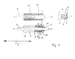
- the pressure spring leaves the thread and lies completely in the spring chamber.
- the last coil of the pressure spring generates a clicking sound, so that the operator is also signaled by an acoustic signal that the union nut has reached its final assembly position. Since the thread in the inner contour of the nut then no longer engages in an external thread, too tight tightening the nut is also effectively prevented.
- the compression spring is completely compressed in the final assembled state. Due to this complete compression, the screw also turns itself, if, for example, the jacket of the line or seal parts set with closed cable gland subsequently.
- the clamping element is configured as a clamping ring with a plurality of parallel clamping fingers or clamping tongues. These clamping fingers or clamping tongues can be pivoted in the direction of the outer jacket of the conduit. The pivoting movement accomplishes this at the end of the nut inside molded inner cone.
- the free ends of the clamping fingers or clamping tongues may have matching contact surfaces or special profiles, for example clamping jaws, on the outer cross section of the line.
- the overall clamping force of the cable gland results from the biasing force of the compression spring after assembly and the additional biasing force generated thereby by the union nut by the complete engagement of the compression spring in the spring chamber 17th
- the thread thread is preceded by a thread start in an advantageous embodiment.
- the union nut when screwed in, strikes the area of the helical compression spring which is fixed on the outer jacket of the sleeve and thus reliably spins the helical compression spring into the thread.
- the compression spring is mounted in an advantageous embodiment between each one arranged on the lateral surface of the sleeve stop and in turn with an axial distance to this stop arranged on the lateral surface of the sleeve arranged counter-stop.
- the axial distance between the stop and the counter-stop can be dimensioned in an advantageous embodiment so that the compression spring is already biased in mounted on the sleeve shell state.
- an arranged in the axial direction next to the clamping element helical bead is provided as a stop.
- the helical bead can also consist of spaced individual segments or similar form elements in a further embodiment.
- the counter-stop, on which the compression spring abuts with its spring tip in the final assembled state, is preferably configured as a flange, wherein a housing wall, in particular a plug connector housing wall, can serve as a counterstop.
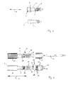
- the cable gland initially has the in Fig. 1 shown sleeve 1 and the end-side clamping ring 2.
- the sleeve 1 is formed by a hollow cylinder and has a passage 3 for a line 4 to be introduced.
- the line 4 is in Fig. 2 first indicated.
- a mounting flange 6 at the in the longitudinal direction 5 to the actual body of the sleeve 1, a mounting flange 6 at.
- the sleeve 1 may for example be adapted to the wall of a device housing.
- the sleeve 1 is then supported with the flange 7 against the housing wall of the electrical device.
- a receiving chamber 8 aligned with the passage 3 is mounted in the area of the mounting flange 6, .
- electrical contact elements can be arranged, which are connected in the final assembled state with the line 4.
- the clamping ring 2 consists of a plurality of axially projecting in the longitudinal direction 5 of the sleeve 1, arranged on a circular line clamping fingers.
- Fig. 2 shows a principle with the representation in Fig. 1 identical sleeve 1.
- a connector housing 10 at the end facing away from the clamping ring 3 of the sleeve 1, a connector housing 10 at.
- plug and / or socket contacts not shown in the drawing can be arranged.
- the inventive cable gland is supplemented by a helical compression spring 11, a radial seal 12 and a union nut 13.
- the radial seal 12 has a passage passage 14 corresponding to the passage 3.
- the union nut 13 is dehumidified inside and has a cable entry end 15 on.
- an inner cone 16 connects.
- the inner cone 16 opens into a spring chamber 17.
- the spring chamber 17 is followed by a thread 18 and a threaded start 19.
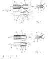
- Fig. 4 and Fig. 5 Based on the representations of Fig. 3, Fig. 4 and Fig. 5 the assembly of the line 4 is explained in more detail.
- the line 4 is inserted through the cable entry 15 through the union nut 13 and pushed through the passageway 3 of the sleeve 1 and the receiving chamber 8 of the connector housing 10.
- the radial seal 12 is in its sealing seat in the clamping ring 2 a.
- the compression spring 11 is pushed over the outer jacket of the sleeve 1.
- the compression spring 11 in the preferred embodiment shown in the figures in the spring tip 22 has a much lower pitch of the spring coils than in the region of the spring end 21. This rising pitch of the spring coil prevents unintentional disassembly of the compression spring 11 of the sleeve 1.
- the compression spring 11 has a significantly greater inherent length in the longitudinal direction 5 in the relaxed state than in the adapted state on the sleeve 1. As a result of the compression of the compression spring 11 in the adapted state between the stop 20 and the effective counter-stop flange 7 or housing wall of the connector housing 10, a bias is already introduced into the compression spring 11.
- the union nut 13 is screwed during assembly by means of initially the threaded portion 19 and then the thread 18 via the compression spring 11 to the union nut 13 on the connector housing 10 and in the embodiment of the sleeve according to FIG Fig. 1 on the flange 7 of the mounting flange 6 abuts ( Fig. 4 ). Subsequently, the union nut 13 is moved on until the last helical turn of the compression spring 11 slides out of the thread 18 out into the spring chamber 17. Since the compression spring 11 is then fully compressed, a clear clicking sound is heard. In addition, the necessary for screwing the nut 13 screwing reduce, so that the nut 13 rotates at completely in the spring chamber 17 inboard compression spring 11 "empty".
Landscapes
- Engineering & Computer Science (AREA)
- Architecture (AREA)
- Civil Engineering (AREA)
- Structural Engineering (AREA)
- Cable Accessories (AREA)
- Installation Of Indoor Wiring (AREA)
- Flexible Shafts (AREA)
- Actuator (AREA)
Abstract
- aus einer zylindrischen Hülse (1) mit einem Durchgangskanal (3) für eine Leitung (4)
-- mit einem Klemmelement an der Einführöffnung des Durchgangskanals (3) und
-- mit einer über den Außenmantel der Hülse (1) geschobenen, an der Hülse (1) widergelagerten wendelförmigen Druckfeder (11) und
- aus einer über die Hülse (1) schraubbaren Überwurfmutter (13) mit einer Innenkontur
-- mit mindestens einem Gewindegang (18), mit welchem die Überwurfmutter (13) über die Druckfeder (11) schraubbar ist,
-- mit einer sich in axialer Richtung an den Gewindegang (18) anschließenden Federkammer (17) für die Aufnahme des überschraubten Bereichs der Druckfeder (11) und
-- mit einer sich in axialer Richtung an die Federkammer (17) anschließenden Innenkontur als Betätiger für das Klemmelement.
Description
- Die Erfindung betrifft eine Kabelverschraubung. Derartige Kabelverschraubungen dienen beispielsweise zur Fixierung einer Leitung am Gehäuse eines Steckverbinders und dienen dabei zugleich als Zugentlastung für die Leitung. Weiterhin dienen Kabelverschraubungen zur Fixierung von Leitungen an Wanddurchführungen in ein elektrisches Gerät. Die Leitung ist dabei durch die Wanddurchführung hindurch von außen in den Innenraum des elektrischen Geräts eingeführt und die Kabelverschraubung fixiert die Leitung im Bereich der Wanddurchführung. Auch sind Kabelverschraubungen bei Anschlussteilen oder sonstigen Schnittstellen für elektrische Leitungen vorhanden.
- Eine Kabelverschraubung ist beispielsweise aus der
DE-OS 1765795 DE-OS 10105232 - Ausgehend hiervon liegt der Erfindung die Aufgabe zugrunde, eine Kabelverschraubung so zu gestalten, dass sie einerseits werkzeuglos montierbar und demontierbar ist und andererseits im montierten Zustand einen sicheren Sitz der Vorrichtung gewährleistet.
- Zur Lösung der Aufgabe ist eine Kabelverschraubung vorgeschlagen mit einer zylindrischen Hülse, durch welche die Leitung hindurchgeführt ist. Die zylindrische Hülse weist ein Klemmelement zur Fixierung der Leitung auf. Zur Betätigung des Klemmelements ist eine Überwurfmutter vorgesehen, welche auf die Hülse aufschraubbar ist. Das Außengewinde der Hülse ist gemäß der Erfindung durch eine wendelförmige Druckfeder gebildet. Die Überwurfmutter weist zum Aufschrauben auf die Druckfeder dementsprechend einen Gewindegang auf. Wird die Überwurfmutter mit Hilfe des Gewindegangs auf die an der Hülse gelagerte Druckfeder aufgeschraubt, bewegt sich die Überwurfmutter entlang der Hülse. In axialer Richtung neben dem Gewindegang in der Innenkontur der Überwurfmutter ist eine Federkammer in die Innenkontur der Überwurfmutter eingebracht, welche den überschraubten Bereich der Druckfeder aufnimmt.
- Ist die Überwurfmutter vollständig auf der Hülse aufgeschraubt, verlässt die Druckfeder den Gewindegang und liegt vollständig in der Federkammer ein. Beim Verlassen des Gewindegangs erzeugt die letzte Wendel der Druckfeder ein klickendes Geräusch, so dass dem Bediener auch durch ein akustisches Signal angezeigt wird, dass die Überwurfmutter ihre Montageendstellung erreicht hat. Da der Gewindegang in der Innenkontur der Überwurfmutter dann in kein Außengewinde mehr eingreift, ist ein zu festes Anziehen der Überwurfmutter ebenfalls wirksam verhindert. Die Druckfeder ist im Montageendzustand vollständig komprimiert. Aufgrund dieser vollständigen Kompression stellt sich die Verschraubung auch selbst nach, wenn sich beispielsweise der Mantel der Leitung oder Dichtungsteile bei geschlossener Kabelverschraubung nachträglich setzen. In Folge des Durchdrehens der Hülse bei vollständig in der Federkammer einliegender Druckfeder ist auch eine Beschädigung der Leitung durch die Einleitung zu hoher Verschraubungskräfte oder -momente wirksam verhindert. Die werkzeuglose Demontage der Überwurfmutter ist problemlos möglich. Zum Lösen der Überwurfmutter wird diese einfach gegen die Einschraubrichtung geschraubt, so dass das Freiende der Druckfeder wieder in den Gewindegang einspurt und die Überwurfmutter über die Druckfeder von der Hülse weggeschraubt werden kann.
- In vorteilhafter Ausgestaltung ist das Klemmelement als Klemmring mit mehreren parallel laufenden Klemmfingern oder Klemmzungen ausgestaltet. Diese Klemmfinger oder Klemmzungen können in Richtung auf den Außenmantel der Leitung verschwenkt werden. Die Schwenkbewegung bewerkstelligt dabei ein am Ende der Überwurfmutter innen eingeformter Innenkonus. Zur Verbesserung der Fixierung der Leitung können die Freienden der Klemmfinger oder Klemmzungen an den Außenquerschnitt der Leitung angepasste Anlageflächen oder besondere Profilierungen, beispielsweise Klemmbacken aufweisen. In diesem Zusammenhang ist es vorteilhaft, einen möglichst großflächigen Anlagebereich der Klemmfinger oder Klemmzunge mit dem Außenmantel der Leitung zu schaffen, um die erforderliche Klemmkraft auf die Leitung zu übertragen. Die Gesamtklemmkraft der Kabelverschraubung resultiert aus der Vorspannkraft der Druckfeder nach der Montage und der durch die Überwurfmutter dadurch erzeugten zusätzlichen Vorspannkraft durch das komplette Einliegen der Druckfeder in der Federkammer 17.
- Zur Vereinfachung der Montage der Überwurfmutter ist in vorteilhafter Ausgestaltung dem Gewindegang ein Gewindeanlauf vorgeschaltet. Mit dem Gewindeanlauf trifft die Überwurfmutter beim Einschrauben gleich auf den am Außenmantel der Hülse festgelegten Bereich der wendelförmigen Druckfeder und spurt so sicher die wendelförmige Druckfeder in den Gewindegang ein.
- Die Druckfeder ist in vorteilhafter Ausgestaltung zwischen jeweils einem auf der Mantelfläche der Hülse angeordneten Anschlag und einem mit axialem Abstand zu diesem Anschlag wiederum auf der Mantelfläche der Hülse angeordneten Gegenanschlag gelagert. Der axiale Abstand zwischen dem Anschlag und dem Gegenanschlag kann in vorteilhafter Ausgestaltung so dimensioniert sein, dass die Druckfeder im auf dem Hülsenmantel montierten Zustand bereits vorgespannt ist.
- In weiterer vorteilhafter Ausgestaltung ist ein in axialer Richtung neben dem Klemmelement angeordneter schraubenförmiger Wulst als Anschlag vorgesehen. Dies hat den montagetechnischen Vorteil, dass die Druckfeder einfach über diesen schraubenförmigen Wulst übergeschraubt werden kann, bis sie mit ihrer Federspitze am Gegenanschlag und ihrem Federende am Anschlag anliegt. Der schraubenförmige Wulst kann in weiterer Ausgestaltung auch aus beabstandeten Einzelsegmenten oder ähnlichen Formelementen bestehen. Der Gegenanschlag, an welchem die Druckfeder mit ihrer Federspitze im Montageendzustand anstößt, ist vorzugsweise flanschartig ausgestaltet, wobei eine Gehäusewand, insbesondere eine Steckverbindergehäusewand, als Gegenanschlag dienen kann.
- Zur Verbesserung des Klemmsitzes des Klemmrings bzw. der Klemmfinger bzw. Klemmzungen des Klemmrings ist in vorteilhafter Ausgestaltung eine kompressible Dichtung zwischen dem Klemmring und der Leitung eingebracht. Anhand der nachstehend dargestellten Ausführungsbeispiele ist die Erfindung mit weiteren Einzelheiten erläutert. Die Zeichnungsfiguren zeigen jeweils oben eine Seitenansicht und unten einen Schnitt durch die darüber dargestellte Seitenansicht der Kabelverschraubung in ihrer jeweiligen Funktionsstellung. Hierbei zeigen:
- Fig. 1
- die Hülse einer Kabelverschraubung mit einem Anschlussgewinde oder einer sonstigen Schnittstelle, wie sie beispielsweise als Wanddurchführung verwendet wird,
- Fig. 2
- eine Kabelverschraubung mit einer als Grundteil für ein Steckverbindergehäuse dienenden Hülse in Explosionsdarstellung,
- Fig. 3
- die in
Fig. 2 dargestellte Kabelverschraubung mit eingeführter Leitung und mit am Gewindeanlauf anliegender Überwurfmutter, - Fig. 4
- die Kabelverschraubung aus
Fig. 3 mit teilweise aufgeschraubter Überwurfmutter sowie - Fig. 5
- die Kabelverschraubung aus
Fig. 3 und Fig. 4 mit vollständig aufgeschraubter Überwurfmutter. - Die Kabelverschraubung weist zunächst die in
Fig. 1 dargestellte Hülse 1 sowie den endseitigen Klemmring 2 auf. Die Hülse 1 ist von einem Hohlzylinder gebildet und weist einen Durchgangskanal 3 für eine einzubringende Leitung 4 auf. Die Leitung 4 ist inFig. 2 erstmals angedeutet. - Bei der in
Fig. 1 dargestellten Ausführungsform schließt sich in Längsrichtung 5 an den eigentlichen Körper der Hülse 1 ein Montageflansch 6 an. Mit Hilfe dieses Montageflansches 6 kann die Hülse 1 beispielsweise an der Wand eines Gerätegehäuses adaptiert sein. Die Hülse 1 stützt sich dann mit der Flanschscheibe 7 gegen die Gehäusewand des elektrischen Geräts. Im Bereich des Montageflansches 6 ist eine mit dem Durchgangskanal 3 fluchtende Aufnahmekammer 8 angebracht. In der Aufnahmekammer 8 können beispielsweise elektrische Kontaktelemente angeordnet sein, welche im Montageendzustand mit der Leitung 4 verbunden sind. - Der Klemmring 2 besteht aus einer Vielzahl von axial in Längsrichtung 5 von der Hülse 1 abragenden, auf einer Kreislinie angeordneten Klemmfingern 9.
-
Fig. 2 zeigt eine prinzipiell mit der Darstellung inFig. 1 baugleiche Hülse 1. Dort schließt sich an das dem Klemmring 3 abgewandte Ende der Hülse 1 ein Steckverbindergehäuse 10 an. In der Aufnahmekammer 8 dieses Steckverbindergehäuses 10 können in der Zeichnung nicht dargestellte Stecker- und/oder Buchsenkontakte angeordnet werden. - Die erfindungsmäßige Kabelverschraubung wird durch eine wendelförmige Druckfeder 11, eine Radialdichtung 12 und eine Überwurfmutter 13 ergänzt. Die Radialdichtung 12 weist einen dem Durchgangskanal 3 entsprechenden Dichtungsdurchgang 14 auf.
- Die Überwurfmutter 13 ist innen ausgehölt und weist endseitig eine Leitungseinführung 15 auf. In Längsrichtung 5 an die Leitungseinführung 15 schließt sich ein Innenkonus 16 an. Der Innenkonus 16 mündet in eine Federkammer 17. An die Federkammer 17 schließt sich ein Gewindegang 18 sowie ein Gewindeanlauf 19 an.
- Anhand der Darstellungen der
Fig. 3, Fig. 4 undFig. 5 ist die Montage der Leitung 4 mit weiteren Einzelheiten erläutert. Die Leitung4 wird durch die Leitungseinführung 15 durch die Überwurfmutter 13 hindurchgesteckt und durch den Durchgangskanal 3 der Hülse 1 und die Aufnahmekammer 8 des Steckverbindergehäuses 10 hindurchgeschoben. Hierbei liegt die Radialdichtung 12 in ihrem Dichtungssitz im Klemmring 2 ein. Die Druckfeder 11 ist über den Außenmantel der Hülse 1 geschoben. - Zum Aufschrauben der Überwurfmutter 13 greift - wie in
Fig. 3 dargestellt - die Überwurfmutter 13 zunächst mit dem Gewindeanlauf 19 an der Druckfeder 11 an. Sobald der Gewindeanlauf 19 die Druckfeder 11 greift, wird die Überwurfmutter 13 in Längsrichtung 5 auf die Druckfeder 11 aufgeschraubt, wobei die Federgänge der Druckfeder 11 zunächst vom Gewindeanlauf 19 erfasst werden. Anschließend wird der Gewindegang 18 über den entsprechenden Gang der Druckfeder 11 geschraubt und der überschraubte Bereich der Druckfeder 11 gerät nach und nach in die Federkammer 17. In der Federkammer 17 wird die Druckfeder 11 kontinuierlich zusammengedrückt. Zugleich drückt der Innenkonus 16 auf die Klemmfinger 9 des Klemmrings 2 und bringt die Klemmfinger 9 mit ihren Enden in ihre Anlagestellung am Außenmantel der Leitung 4. Die Radialdichtung 12 wird dabei von den Klemmfingern 9 komprimiert. - In den Zeichnungsfiguren ist weiterhin der aus mehreren Segementen zusammengesetzte, als Anschlag 20 wirksame schraubenförmige Wulst erkennbar. Die Druckfeder 11 wird bei der Montage mit ihrer Federspitze 22 voraus über den schraubenförmigen Anschlag 20 so lange übergeschraubt, bis die Federspitze 22 an dem der Hülse 1 zugewandten Ende der Flanschscheibe 7 bzw. der der Hülse 1 zugewandten Gehäusewand des Steckverbindergehäuses 10 anliegt. Diese Anlagestellung ist in
Fig. 3 gezeigt. Das in Längsrichtung 5 der Federspitze 22 abgewandte Federende 21 liegt bei vollständig montierter Druckfeder 11 an der dem Flansch 7 bzw. dem Steckverbindergehäuse 10 zugewandten Wandung des Anschlags 20 an. Insbesondere aus der Darstellung derFig. 2 ist gut erkennbar, dass die Druckfeder 11 in der in den Figuren gezeigten bevorzugten Ausführungsform im Bereich der Federspitze 22 eine deutlich geringere Steigung der Federwendeln aufweist als im Bereich des Federendes 21. Diese ansteigende Steigung der Federwendel verhindert eine unbeabsichtigte Demontage der Druckfeder 11 von der Hülse 1. Die Druckfeder 11 weist im entspannten Zustand eine deutlich größere Eigenlänge in Längsrichtung 5 auf als im auf der Hülse 1 adaptierten Zustand. In Folge der Stauchung der Druckfeder 11 im adaptierten Zustand zwischen dem Anschlag 20 und der als Gegenanschlag wirksamen Flanschscheibe 7 bzw. Gehäusewand des Steckverbindergehäuses 10 ist bereits eine Vorspannung in die Druckfeder 11 eingebracht. Dies bewirkt eine gewisse und gewollte Lagesicherung der Druckfeder 11 auf der Hülse 1, wodurch das Aufschrauben der Überwurfmutter 13 begünstigt wird. Beim Aufschrauben der Überwurfmutter 13 verdreht sich nämlich die als Innengewinde wirksame Druckfeder 11 nicht. Ferner wird durch die bereits im vormontierten Zustand eingebrachte Vorspannkraft ein gewisser Anteil der gesamten Klemmkraft der Kabelverschraubung in das System eingebracht - Bei vollständig aufgeschraubter Überwurfmutter 13 (siehe Darstellung in
Fig. 5 ) liegt die Druckfeder 11 vollständig in der Federkammer 17 ein. Dies bedeutet zugleich, dass keine Federgänge der Druckfeder 11 mehr im Gewindegang 18 oder im Gewindeanlauf 19 einliegen. Die Druckfeder 11 liegt vollständig in der Federkammer 17 und ist maximal vorgespannt (Fig. 5 ). Auf diese Weise übt die Druckfeder 11 in Längsrichtung 5 ihre Druckspannung auf die Überwurfmutter 13 und damit auf den Klemmring 2 mit seinen Klemmfingern 9 aus. Hervorzuheben ist die Tatsache, dass durch die dauernde mittelbare Einwirkung der Druckfeder 11 auf den Innenkonus 16 und damit auf den Klemmring 12 sich die Kabelverschraubung selbsttätig nachstellt, so dass stets gewährleistet ist, dass die erforderlichen Haltekräfte auf die Leitung 4 einwirken. Außerdem ermöglicht es die erfindungsmäßige Kabelverschraubung Leitung 4 mit unterschiedlichen Leitungsdurchmessern bzw. Leitungsquerschnitten zu fixieren. Sind kleinere Durchmesser oder Querschnitte vorhanden, wirken geringere Klemmkräfte. Mit steigenden Durchmessern der Leitung 4 steigen auch die auf die Leitung 4 einwirkenden Klemmkräfte. - Die Montage und Demontage der Überwurfmutter 13 ist ohne zur Hilfenahme von Werkzeugen problemlos möglich. Ausgehend von der in
Fig. 3 dargestellten Position wird die Überwurfmutter 13 bei der Montage mit Hilfe zunächst des Gewindeanlaufs 19 und anschließend des Gewindegangs 18 über die Druckfeder 11 geschraubt bis die Überwurfmutter 13 am Steckverbindergehäuse 10 bzw. bei der Ausführungsform der Hülse gemäßFig. 1 an der Flanschscheibe 7 des Montageflansches 6 anliegt (Fig. 4 ). Anschließend wird die Überwurfmutter 13 so lange weiter bewegt, bis der letzte Wendelgang der Druckfeder 11 aus dem Gewindegang 18 heraus in die Federkammer 17 hineingleitet. Da die Druckfeder 11 dann vollständig komprimiert ist, ist ein deutliches Klickgeräusch zu hören. Außerdem verringern sich die für das Einschrauben der Überwurfmutter 13 erforderlichen Schraubkräfte, so dass die Überwurfmutter 13 bei vollständig in der Federkammer 17 einliegender Druckfeder 11 "leer" dreht. - Zum Öffnen der Kabelverschraubung muss die Überwurfmutter 13 lediglich in Längsrichtung 5 vom Steckverbindergehäuse 10 bzw. vom Montageflansch 6 weggeschraubt werden. Die Druckfeder 11 spurt sodann in Folge des Federdrucks wieder in den Gewindegang 18 und anschließend in den Gewindeanlauf 19 ein, so dass die Überwurfmutter 13 aus ihrer in
Fig. 5 dargestellten Schließstellung in ihre inFig. 3 dargestellte Öffnungsstellung wieder zurückgeschraubt werden und anschließend abgezogen werden kann, was inFig. 2 dargestellt ist. - Hervorzuheben ist die platzsparende Bauweise und die Tatsache der ausschließlich in Längsrichtung 5 wirkenden Kräfte. Außerdem erfolgen sämtliche Bewegungen in Längsrichtung 5, was die Montage auch unter beengten Platzverhältnissen begünstigt.
-
- 1
- Hülse
- 2
- Klemmring
- 3
- Durchgangskanal
- 4
- Leitung
- 5
- Längsrichtung
- 6
- Montageflansch
- 7
- Flanschscheibe
- 8
- Aufnahmekammer
- 9
- Klemmfinger
- 10
- Steckverbindergehäuse
- 11
- Druckfeder
- 12
- Radialrichtung
- 13
- Überwurfmutter
- 14
- Dichtungsdurchgang
- 15
- Leitungseinführung
- 16
- Innenkonus
- 17
- Federkammer
- 18
- Gewindegang
- 19
- Gewindeanlauf
- 20
- Anschlag
- 21
- Federende
- 22
- Federspitze
Claims (6)
- Kabelverschraubung bestehend- aus einer zylindrischen Hülse (1) mit einem Durchgangskanal (3) für eine Leitung (4)-- mit einem Klemmelement an der Einführöffnung des Durchgangskanals (3) und-- mit einer über den Außenmantel der Hülse (1) geschobenen, an der Hülse (1) widergelagerten wendelförmigen Druckfeder (11) und- aus einer über die Hülse (1) schraubbaren Überwurfmutter (13) mit einer Innenkontur-- mit mindestens einem Gewindegang (18), mit welchem die Überwurfmutter (13) über die Druckfeder (11) schraubbar ist,-- mit einer sich in axialer Richtung an den Gewindegang (18) anschließenden Federkammer (17) für die Aufnahme des überschraubten Bereichs der Druckfeder (11) und-- mit einer sich in axialer Richtung an die Federkammer (17) anschließenden Innenkontur als Betätiger für das Klemmelement.
- Kabelverschraubung nach Anspruch 1
gekennzeichnet durch
einen aus mehreren schwenkbaren Klemmfingern (9) gebildeten Klemmring (2) als Klemmelement und einen Innenkonus (16) am Ende der Überwurfmutter (13) als Betätiger für den Klemmring (2) - Kabelverschraubung nach Anspruch 1 oder 2
gekennzeichnet durch einen Gewindeanlauf (19) an der Vorderseite der Überwurfmutter (13) und einen sich an den Gewindeanlauf (19) anschließenden Gewindegang (18). - Kabelverschraubung nach einem der Ansprüche 1 bis 3
gekennzeichnet durch,
einen in axialer Richtung neben dem Klemmelement angeordneten Anschlag (20) und einen mit axialem Abstand zum Anschlag (20) angeordneten Gegenanschlag für die Druckfeder (11). - Kabelverschraubung nach Anspruch 4
gekennzeichnet durch einen schraubförmigen Wulst als Anschlag (20) und einen Flansch als Gegenanschlag. - Kabelverschraubung nach Anspruch 5
dadurch gekennzeichnet dass die Gehäuserückwand eines Steckverbindergehäuses (10) den als Gegenanschlag wirksamen Flansch bildet
Applications Claiming Priority (1)
| Application Number | Priority Date | Filing Date | Title |
|---|---|---|---|
| DE102013008405.9A DE102013008405A1 (de) | 2013-05-17 | 2013-05-17 | Kabelverschraubung |
Publications (3)
| Publication Number | Publication Date |
|---|---|
| EP2804275A2 true EP2804275A2 (de) | 2014-11-19 |
| EP2804275A3 EP2804275A3 (de) | 2015-01-07 |
| EP2804275B1 EP2804275B1 (de) | 2019-08-07 |
Family
ID=50630593
Family Applications (1)
| Application Number | Title | Priority Date | Filing Date |
|---|---|---|---|
| EP14166103.3A Active EP2804275B1 (de) | 2013-05-17 | 2014-04-25 | Kabelverschraubung |
Country Status (2)
| Country | Link |
|---|---|
| EP (1) | EP2804275B1 (de) |
| DE (1) | DE102013008405A1 (de) |
Cited By (1)
| Publication number | Priority date | Publication date | Assignee | Title |
|---|---|---|---|---|
| CN119401308A (zh) * | 2025-01-06 | 2025-02-07 | 山东源鸿线缆有限公司 | 一种用于潜水泵的防水软电缆及安装方法 |
Citations (2)
| Publication number | Priority date | Publication date | Assignee | Title |
|---|---|---|---|---|
| DE1765795A1 (de) | 1968-07-18 | 1971-08-26 | Wilhelm Geissel Fa | Kabelverschraubung |
| DE10105232A1 (de) | 2001-02-02 | 2002-08-08 | Aloys Mennekes Anlagengmbh & C | Steckvorrichtung |
Family Cites Families (7)
| Publication number | Priority date | Publication date | Assignee | Title |
|---|---|---|---|---|
| US4141117A (en) * | 1977-06-09 | 1979-02-27 | Brammall, Inc. | Releasing tool for use with a releasable cone lock |
| JPS5744731Y2 (de) * | 1978-01-26 | 1982-10-02 | ||
| US5464300A (en) * | 1993-04-29 | 1995-11-07 | Crainich; Lawrence | Medical instrument and coupling apparatus for same |
| GB9919691D0 (en) * | 1999-08-19 | 1999-10-20 | British Engines Ltd | Gland assembly |
| US6677536B2 (en) * | 2001-02-06 | 2004-01-13 | Endress + Hauser Gmbh + Co. Kg | Cable bushing |
| DE10312749B4 (de) * | 2003-03-21 | 2005-11-03 | Pflitsch Gmbh & Co. Kg | Verschraubung für abgedichtete Leitungsdurchführungen |
| IT1396378B1 (it) * | 2009-10-29 | 2012-11-19 | Meccanica Finnord Spa | Dispositivo per la regolazione automatica della tensione applicata a un cavo di controllo. |
-
2013
- 2013-05-17 DE DE102013008405.9A patent/DE102013008405A1/de not_active Withdrawn
-
2014
- 2014-04-25 EP EP14166103.3A patent/EP2804275B1/de active Active
Patent Citations (2)
| Publication number | Priority date | Publication date | Assignee | Title |
|---|---|---|---|---|
| DE1765795A1 (de) | 1968-07-18 | 1971-08-26 | Wilhelm Geissel Fa | Kabelverschraubung |
| DE10105232A1 (de) | 2001-02-02 | 2002-08-08 | Aloys Mennekes Anlagengmbh & C | Steckvorrichtung |
Cited By (1)
| Publication number | Priority date | Publication date | Assignee | Title |
|---|---|---|---|---|
| CN119401308A (zh) * | 2025-01-06 | 2025-02-07 | 山东源鸿线缆有限公司 | 一种用于潜水泵的防水软电缆及安装方法 |
Also Published As
| Publication number | Publication date |
|---|---|
| EP2804275B1 (de) | 2019-08-07 |
| EP2804275A3 (de) | 2015-01-07 |
| DE102013008405A1 (de) | 2014-11-20 |
Similar Documents
| Publication | Publication Date | Title |
|---|---|---|
| DE102010061067B4 (de) | Vorrichtung zur Fixierung eines Kabels an einen Kabelabgangsstutzen | |
| EP2299547B1 (de) | Steckverbindergehaeuse mit integrierter Kabelklemmung | |
| DE10312749B4 (de) | Verschraubung für abgedichtete Leitungsdurchführungen | |
| EP1675244A2 (de) | Verschraubung für abgedichtete Leitungsdurchführungen | |
| EP2593995A2 (de) | Kabelzugentlastung | |
| DE2647043C2 (de) | Zugentlastungsvorrichtung für eine Kabeleinführung in ein Gehäuse eines elektrischen Gerätes | |
| DE102018005690A1 (de) | Flexibler Doppelhelix Marknagel | |
| EP2439825A2 (de) | Vorrichtung zur zugentlastenden Festlegung von Kabeln | |
| WO2012142640A1 (de) | Zahnprothese | |
| DE202011050587U1 (de) | Elektrisches Anschlussteil | |
| EP2804275B1 (de) | Kabelverschraubung | |
| EP3706661B1 (de) | Schraubgetriebe | |
| DE102008061269A1 (de) | Kabelverschraubung | |
| DE202004019698U1 (de) | Verschraubung für abgedichtete Leitungsdurchführungen | |
| DE19826380B4 (de) | Osteosynthetisches Befestigungssystem | |
| EP3404777B1 (de) | Geräteanschluss | |
| DE2309649A1 (de) | Kabelverschraubung | |
| DE202015107162U1 (de) | Sensorarmatur | |
| DE102013014200A1 (de) | Kontaktelement mit einem klemmenden Anschluss für Litzenleiter | |
| DE102011121089A1 (de) | Vorrichtung zum Halten und Abdichten eines Rohres | |
| DE202018101002U1 (de) | Rohranschluss und Rohrverbindung | |
| DE3306115A1 (de) | Stiftstecker fuer den elektrodenanschluss eines herzschrittmachers | |
| DE102005056413B4 (de) | Taschenmutter einer Schraubverbindung zum Verbinden von Bauteilen | |
| CH714541A2 (de) | Kabelverschraubung. | |
| DE202004016541U1 (de) | Adapter eines elektrischen Steckverbinders sowie Steckverbinder mit einem solchen Adapter |
Legal Events
| Date | Code | Title | Description |
|---|---|---|---|
| PUAI | Public reference made under article 153(3) epc to a published international application that has entered the european phase |
Free format text: ORIGINAL CODE: 0009012 |
|
| 17P | Request for examination filed |
Effective date: 20140425 |
|
| AK | Designated contracting states |
Kind code of ref document: A2 Designated state(s): AL AT BE BG CH CY CZ DE DK EE ES FI FR GB GR HR HU IE IS IT LI LT LU LV MC MK MT NL NO PL PT RO RS SE SI SK SM TR |
|
| AX | Request for extension of the european patent |
Extension state: BA ME |
|
| PUAL | Search report despatched |
Free format text: ORIGINAL CODE: 0009013 |
|
| AK | Designated contracting states |
Kind code of ref document: A3 Designated state(s): AL AT BE BG CH CY CZ DE DK EE ES FI FR GB GR HR HU IE IS IT LI LT LU LV MC MK MT NL NO PL PT RO RS SE SI SK SM TR |
|
| AX | Request for extension of the european patent |
Extension state: BA ME |
|
| RIC1 | Information provided on ipc code assigned before grant |
Ipc: H02G 3/06 20060101AFI20141204BHEP Ipc: H02G 15/04 20060101ALI20141204BHEP |
|
| R17P | Request for examination filed (corrected) |
Effective date: 20150601 |
|
| RBV | Designated contracting states (corrected) |
Designated state(s): AL AT BE BG CH CY CZ DE DK EE ES FI FR GB GR HR HU IE IS IT LI LT LU LV MC MK MT NL NO PL PT RO RS SE SI SK SM TR |
|
| STAA | Information on the status of an ep patent application or granted ep patent |
Free format text: STATUS: EXAMINATION IS IN PROGRESS |
|
| 17Q | First examination report despatched |
Effective date: 20170103 |
|
| GRAP | Despatch of communication of intention to grant a patent |
Free format text: ORIGINAL CODE: EPIDOSNIGR1 |
|
| STAA | Information on the status of an ep patent application or granted ep patent |
Free format text: STATUS: GRANT OF PATENT IS INTENDED |
|
| INTG | Intention to grant announced |
Effective date: 20190515 |
|
| GRAS | Grant fee paid |
Free format text: ORIGINAL CODE: EPIDOSNIGR3 |
|
| GRAA | (expected) grant |
Free format text: ORIGINAL CODE: 0009210 |
|
| STAA | Information on the status of an ep patent application or granted ep patent |
Free format text: STATUS: THE PATENT HAS BEEN GRANTED |
|
| AK | Designated contracting states |
Kind code of ref document: B1 Designated state(s): AL AT BE BG CH CY CZ DE DK EE ES FI FR GB GR HR HU IE IS IT LI LT LU LV MC MK MT NL NO PL PT RO RS SE SI SK SM TR |
|
| REG | Reference to a national code |
Ref country code: GB Ref legal event code: FG4D Free format text: NOT ENGLISH |
|
| REG | Reference to a national code |
Ref country code: CH Ref legal event code: EP Ref country code: AT Ref legal event code: REF Ref document number: 1165283 Country of ref document: AT Kind code of ref document: T Effective date: 20190815 |
|
| REG | Reference to a national code |
Ref country code: DE Ref legal event code: R096 Ref document number: 502014012352 Country of ref document: DE |
|
| REG | Reference to a national code |
Ref country code: IE Ref legal event code: FG4D Free format text: LANGUAGE OF EP DOCUMENT: GERMAN |
|
| REG | Reference to a national code |
Ref country code: NL Ref legal event code: MP Effective date: 20190807 |
|
| REG | Reference to a national code |
Ref country code: LT Ref legal event code: MG4D |
|
| PG25 | Lapsed in a contracting state [announced via postgrant information from national office to epo] |
Ref country code: PT Free format text: LAPSE BECAUSE OF FAILURE TO SUBMIT A TRANSLATION OF THE DESCRIPTION OR TO PAY THE FEE WITHIN THE PRESCRIBED TIME-LIMIT Effective date: 20191209 Ref country code: NO Free format text: LAPSE BECAUSE OF FAILURE TO SUBMIT A TRANSLATION OF THE DESCRIPTION OR TO PAY THE FEE WITHIN THE PRESCRIBED TIME-LIMIT Effective date: 20191107 Ref country code: HR Free format text: LAPSE BECAUSE OF FAILURE TO SUBMIT A TRANSLATION OF THE DESCRIPTION OR TO PAY THE FEE WITHIN THE PRESCRIBED TIME-LIMIT Effective date: 20190807 Ref country code: SE Free format text: LAPSE BECAUSE OF FAILURE TO SUBMIT A TRANSLATION OF THE DESCRIPTION OR TO PAY THE FEE WITHIN THE PRESCRIBED TIME-LIMIT Effective date: 20190807 Ref country code: FI Free format text: LAPSE BECAUSE OF FAILURE TO SUBMIT A TRANSLATION OF THE DESCRIPTION OR TO PAY THE FEE WITHIN THE PRESCRIBED TIME-LIMIT Effective date: 20190807 Ref country code: LT Free format text: LAPSE BECAUSE OF FAILURE TO SUBMIT A TRANSLATION OF THE DESCRIPTION OR TO PAY THE FEE WITHIN THE PRESCRIBED TIME-LIMIT Effective date: 20190807 Ref country code: NL Free format text: LAPSE BECAUSE OF FAILURE TO SUBMIT A TRANSLATION OF THE DESCRIPTION OR TO PAY THE FEE WITHIN THE PRESCRIBED TIME-LIMIT Effective date: 20190807 Ref country code: BG Free format text: LAPSE BECAUSE OF FAILURE TO SUBMIT A TRANSLATION OF THE DESCRIPTION OR TO PAY THE FEE WITHIN THE PRESCRIBED TIME-LIMIT Effective date: 20191107 |
|
| PG25 | Lapsed in a contracting state [announced via postgrant information from national office to epo] |
Ref country code: ES Free format text: LAPSE BECAUSE OF FAILURE TO SUBMIT A TRANSLATION OF THE DESCRIPTION OR TO PAY THE FEE WITHIN THE PRESCRIBED TIME-LIMIT Effective date: 20190807 Ref country code: AL Free format text: LAPSE BECAUSE OF FAILURE TO SUBMIT A TRANSLATION OF THE DESCRIPTION OR TO PAY THE FEE WITHIN THE PRESCRIBED TIME-LIMIT Effective date: 20190807 Ref country code: LV Free format text: LAPSE BECAUSE OF FAILURE TO SUBMIT A TRANSLATION OF THE DESCRIPTION OR TO PAY THE FEE WITHIN THE PRESCRIBED TIME-LIMIT Effective date: 20190807 Ref country code: GR Free format text: LAPSE BECAUSE OF FAILURE TO SUBMIT A TRANSLATION OF THE DESCRIPTION OR TO PAY THE FEE WITHIN THE PRESCRIBED TIME-LIMIT Effective date: 20191108 Ref country code: IS Free format text: LAPSE BECAUSE OF FAILURE TO SUBMIT A TRANSLATION OF THE DESCRIPTION OR TO PAY THE FEE WITHIN THE PRESCRIBED TIME-LIMIT Effective date: 20191207 Ref country code: RS Free format text: LAPSE BECAUSE OF FAILURE TO SUBMIT A TRANSLATION OF THE DESCRIPTION OR TO PAY THE FEE WITHIN THE PRESCRIBED TIME-LIMIT Effective date: 20190807 |
|
| PG25 | Lapsed in a contracting state [announced via postgrant information from national office to epo] |
Ref country code: TR Free format text: LAPSE BECAUSE OF FAILURE TO SUBMIT A TRANSLATION OF THE DESCRIPTION OR TO PAY THE FEE WITHIN THE PRESCRIBED TIME-LIMIT Effective date: 20190807 |
|
| PG25 | Lapsed in a contracting state [announced via postgrant information from national office to epo] |
Ref country code: IT Free format text: LAPSE BECAUSE OF FAILURE TO SUBMIT A TRANSLATION OF THE DESCRIPTION OR TO PAY THE FEE WITHIN THE PRESCRIBED TIME-LIMIT Effective date: 20190807 Ref country code: RO Free format text: LAPSE BECAUSE OF FAILURE TO SUBMIT A TRANSLATION OF THE DESCRIPTION OR TO PAY THE FEE WITHIN THE PRESCRIBED TIME-LIMIT Effective date: 20190807 Ref country code: EE Free format text: LAPSE BECAUSE OF FAILURE TO SUBMIT A TRANSLATION OF THE DESCRIPTION OR TO PAY THE FEE WITHIN THE PRESCRIBED TIME-LIMIT Effective date: 20190807 Ref country code: PL Free format text: LAPSE BECAUSE OF FAILURE TO SUBMIT A TRANSLATION OF THE DESCRIPTION OR TO PAY THE FEE WITHIN THE PRESCRIBED TIME-LIMIT Effective date: 20190807 Ref country code: DK Free format text: LAPSE BECAUSE OF FAILURE TO SUBMIT A TRANSLATION OF THE DESCRIPTION OR TO PAY THE FEE WITHIN THE PRESCRIBED TIME-LIMIT Effective date: 20190807 |
|
| PG25 | Lapsed in a contracting state [announced via postgrant information from national office to epo] |
Ref country code: CZ Free format text: LAPSE BECAUSE OF FAILURE TO SUBMIT A TRANSLATION OF THE DESCRIPTION OR TO PAY THE FEE WITHIN THE PRESCRIBED TIME-LIMIT Effective date: 20190807 Ref country code: SM Free format text: LAPSE BECAUSE OF FAILURE TO SUBMIT A TRANSLATION OF THE DESCRIPTION OR TO PAY THE FEE WITHIN THE PRESCRIBED TIME-LIMIT Effective date: 20190807 Ref country code: IS Free format text: LAPSE BECAUSE OF FAILURE TO SUBMIT A TRANSLATION OF THE DESCRIPTION OR TO PAY THE FEE WITHIN THE PRESCRIBED TIME-LIMIT Effective date: 20200224 Ref country code: SK Free format text: LAPSE BECAUSE OF FAILURE TO SUBMIT A TRANSLATION OF THE DESCRIPTION OR TO PAY THE FEE WITHIN THE PRESCRIBED TIME-LIMIT Effective date: 20190807 |
|
| REG | Reference to a national code |
Ref country code: DE Ref legal event code: R097 Ref document number: 502014012352 Country of ref document: DE |
|
| PLBE | No opposition filed within time limit |
Free format text: ORIGINAL CODE: 0009261 |
|
| STAA | Information on the status of an ep patent application or granted ep patent |
Free format text: STATUS: NO OPPOSITION FILED WITHIN TIME LIMIT |
|
| PG2D | Information on lapse in contracting state deleted |
Ref country code: IS |
|
| PGFP | Annual fee paid to national office [announced via postgrant information from national office to epo] |
Ref country code: FR Payment date: 20200421 Year of fee payment: 7 |
|
| 26N | No opposition filed |
Effective date: 20200603 |
|
| PG25 | Lapsed in a contracting state [announced via postgrant information from national office to epo] |
Ref country code: SI Free format text: LAPSE BECAUSE OF FAILURE TO SUBMIT A TRANSLATION OF THE DESCRIPTION OR TO PAY THE FEE WITHIN THE PRESCRIBED TIME-LIMIT Effective date: 20190807 |
|
| PGFP | Annual fee paid to national office [announced via postgrant information from national office to epo] |
Ref country code: GB Payment date: 20200423 Year of fee payment: 7 |
|
| PG25 | Lapsed in a contracting state [announced via postgrant information from national office to epo] |
Ref country code: MC Free format text: LAPSE BECAUSE OF FAILURE TO SUBMIT A TRANSLATION OF THE DESCRIPTION OR TO PAY THE FEE WITHIN THE PRESCRIBED TIME-LIMIT Effective date: 20190807 |
|
| REG | Reference to a national code |
Ref country code: CH Ref legal event code: PL |
|
| PG25 | Lapsed in a contracting state [announced via postgrant information from national office to epo] |
Ref country code: CH Free format text: LAPSE BECAUSE OF NON-PAYMENT OF DUE FEES Effective date: 20200430 Ref country code: LU Free format text: LAPSE BECAUSE OF NON-PAYMENT OF DUE FEES Effective date: 20200425 Ref country code: LI Free format text: LAPSE BECAUSE OF NON-PAYMENT OF DUE FEES Effective date: 20200430 |
|
| REG | Reference to a national code |
Ref country code: BE Ref legal event code: MM Effective date: 20200430 |
|
| PG25 | Lapsed in a contracting state [announced via postgrant information from national office to epo] |
Ref country code: BE Free format text: LAPSE BECAUSE OF NON-PAYMENT OF DUE FEES Effective date: 20200430 |
|
| PG25 | Lapsed in a contracting state [announced via postgrant information from national office to epo] |
Ref country code: IE Free format text: LAPSE BECAUSE OF NON-PAYMENT OF DUE FEES Effective date: 20200425 |
|
| REG | Reference to a national code |
Ref country code: AT Ref legal event code: MM01 Ref document number: 1165283 Country of ref document: AT Kind code of ref document: T Effective date: 20200425 |
|
| PG25 | Lapsed in a contracting state [announced via postgrant information from national office to epo] |
Ref country code: AT Free format text: LAPSE BECAUSE OF NON-PAYMENT OF DUE FEES Effective date: 20200425 |
|
| GBPC | Gb: european patent ceased through non-payment of renewal fee |
Effective date: 20210425 |
|
| PG25 | Lapsed in a contracting state [announced via postgrant information from national office to epo] |
Ref country code: FR Free format text: LAPSE BECAUSE OF NON-PAYMENT OF DUE FEES Effective date: 20210430 Ref country code: GB Free format text: LAPSE BECAUSE OF NON-PAYMENT OF DUE FEES Effective date: 20210425 |
|
| PG25 | Lapsed in a contracting state [announced via postgrant information from national office to epo] |
Ref country code: MT Free format text: LAPSE BECAUSE OF FAILURE TO SUBMIT A TRANSLATION OF THE DESCRIPTION OR TO PAY THE FEE WITHIN THE PRESCRIBED TIME-LIMIT Effective date: 20190807 Ref country code: CY Free format text: LAPSE BECAUSE OF FAILURE TO SUBMIT A TRANSLATION OF THE DESCRIPTION OR TO PAY THE FEE WITHIN THE PRESCRIBED TIME-LIMIT Effective date: 20190807 |
|
| PG25 | Lapsed in a contracting state [announced via postgrant information from national office to epo] |
Ref country code: MK Free format text: LAPSE BECAUSE OF FAILURE TO SUBMIT A TRANSLATION OF THE DESCRIPTION OR TO PAY THE FEE WITHIN THE PRESCRIBED TIME-LIMIT Effective date: 20190807 |
|
| PGFP | Annual fee paid to national office [announced via postgrant information from national office to epo] |
Ref country code: DE Payment date: 20240429 Year of fee payment: 11 |
|
| REG | Reference to a national code |
Ref country code: DE Ref legal event code: R119 Ref document number: 502014012352 Country of ref document: DE |
|
| REG | Reference to a national code |
Ref country code: DE Ref legal event code: R082 Ref document number: 502014012352 Country of ref document: DE Representative=s name: TERGAU & WALKENHORST INTELLECTUAL PROPERTY GMB, DE |
|
| PG25 | Lapsed in a contracting state [announced via postgrant information from national office to epo] |
Ref country code: DE Free format text: LAPSE BECAUSE OF NON-PAYMENT OF DUE FEES Effective date: 20251104 |