EP2804328A1 - Verfahren und Vorrichtung zur Bestimmung von Drahtwiderstand - Google Patents
Verfahren und Vorrichtung zur Bestimmung von Drahtwiderstand Download PDFInfo
- Publication number
- EP2804328A1 EP2804328A1 EP14168547.9A EP14168547A EP2804328A1 EP 2804328 A1 EP2804328 A1 EP 2804328A1 EP 14168547 A EP14168547 A EP 14168547A EP 2804328 A1 EP2804328 A1 EP 2804328A1
- Authority
- EP
- European Patent Office
- Prior art keywords
- wire
- resistance
- conductor
- wires
- loop
- Prior art date
- Legal status (The legal status is an assumption and is not a legal conclusion. Google has not performed a legal analysis and makes no representation as to the accuracy of the status listed.)
- Granted
Links
Images



Classifications
-
- G—PHYSICS
- G01—MEASURING; TESTING
- G01N—INVESTIGATING OR ANALYSING MATERIALS BY DETERMINING THEIR CHEMICAL OR PHYSICAL PROPERTIES
- G01N27/00—Investigating or analysing materials by the use of electric, electrochemical, or magnetic means
- G01N27/02—Investigating or analysing materials by the use of electric, electrochemical, or magnetic means by investigating impedance
- G01N27/04—Investigating or analysing materials by the use of electric, electrochemical, or magnetic means by investigating impedance by investigating resistance
-
- H—ELECTRICITY
- H04—ELECTRIC COMMUNICATION TECHNIQUE
- H04B—TRANSMISSION
- H04B3/00—Line transmission systems
- H04B3/02—Details
- H04B3/46—Monitoring; Testing
Definitions
- the invention generally relates to communication networks, and more particularly, to a method and system for determining resistance imbalance in communications cables.
- PoE Power over Ethernet
- a way to deliver electrical power over LAN cabling to networked devices has been widely deployed over the years to provide power to various endpoints in the enterprise workspace environment using existing conductors.
- PoE Power Over Ethernet
- End user PoE equipment such as telephones and video cameras, are conveniently powered through the ethernet jack, thus eliminating the need for a local AC power outlet.
- PoE systems typically transmit electrical power by using one twisted pair of a datacomm cabling system containing four twisted pair communication channels to send current to equipment, and another pair to return the current to the power source. Each pair is also typically connected to ferrite core transformers (baluns) that convert the differential twisted pair signal to a single ended signal for subsequent processing. PoE current flows through the transformer windings with each wire preferably carrying half of the current. The two currents induce equal and opposite DC flux in the transformer ferrite core, resulting in cancellation and no DC flux. It is to be appreciated that any remnant DC flux can degrade the transformer's performance due to core saturation resulting in possible degradation of data transmission.
- the invention includes, in one aspect, a method and apparatus for qualifying a conductor for services and to determine imbalance resistance of the conductor.
- the method and apparatus comprises feeding signals from a controller to termination ends of at least three wires of a conductor, then determining in the controller a resistance difference between first and second wires of the conductor using a measured resistance of one of the three conductor wires as a reference value.
- the conductor is qualified for services when the resistance difference between the first and second wires is below a threshold.
- Another aspect of the invention relates to determining imbalance resistance of a conductor having at least three wires by first determining a resistance value of a first wire loop consisting of an aggregate resistance of any two of the at least three conductor wires. Next, a resistance value of a second wire loop is determinied, with the loop consisting of an aggregate resistance of one of the wires used in determination of the first loop and a conductor wire not used in determination of the first wire loop. A resistance difference is then determined between the first and second wire loops. And intra-pair resistance imbalance is determined for the conductor according to the determined resistance difference.
- Another aspect of the invention relates to an apparatus and method to measure single wire resistance in a communication cable having at least first and second wire pairs.
- the method and apparatus comprises first measuring resistance between a first wire of a first wire pair and one reference wire chosen from a second wire pair to produce a first loop resistance measurement value. Next, resistance between a second wire of the first wire pair and the reference wire is measured to produce a second loop resistance value. Next, resistance between the first wire and the second wire of the first wire pair is measured to produce a third loop resistance measurement value. Resistance of the first wire is determined by calculating a resistance sum value by adding the third loop value to a difference between the first and second loop values and dividing the resistance sum value in half.
- the aforementioned services comprise low-voltage DC power transmission.
- Each of the first and second wires may be constituents of a twisted pair of wires.
- the resistance of each wire is determined by measuring the resistance at one end of the wire while the other end of the wire is coupled to the controller.
- the aforementioned communication cable may be a twisted pair datacomm cable.
- at least one of the wires used in the loop measurement determinations may be a wire shield.
- the embodiments of this invention as discussed below are preferably a software algorithm, program or code residing on computer useable medium having control logic for enabling execution on a machine having a computer processor.
- the machine typically includes memory storage configured to provide output from execution of the computer algorithm or program.
- the term "software” is meant to be synonymous with any code or program that can be in a processor of a host computer, regardless of whether the implementation is in hardware, firmware or as a software computer product available on a disc, a memory storage device, or for download from a remote machine.
- the embodiments described herein include such software to implement the equations, relationships and algorithms described above.
- One skilled in the art will appreciate further features and advantages of the invention based on the above-described embodiments. Accordingly, the invention is not to be limited by what has been particularly shown and described, except as indicated by the appended claims. All publications and references cited herein are expressly incorporated herein by reference in their entirety.
- FIG. 1 depicts an exemplary general-purpose computing system in which illustrated embodiments of the present invention may be implemented.
- FIG. 1 illustrating a processing system 100 which generally comprises at least one processor 102, or processing unit or plurality of processors, memory 104, at least one input device 106 and at least one output device 108, coupled together via a bus or group of buses 110.
- input device 106 and output device 108 could be the same device.
- An interface 112 can also be provided for coupling the processing system 100 to one or more peripheral devices, for example interface 112 could be a PCI card or PC card.
- At least one storage device 114 which houses at least one database 116 can also be provided.
- the memory 104 can be any form of memory device, for example, volatile or non-volatile memory, solid state storage devices, magnetic devices, etc.
- the processor 102 could comprise more than one distinct processing device, for example to handle different functions within the processing system 100.
- Input device 106 receives input data 118 and can comprise, for example, a keyboard, a pointer device such as a pen-like device or a mouse, audio receiving device for voice controlled activation such as a microphone, data receiver or antenna such as a modem or wireless data adaptor, data acquisition card, etc.
- Input data 118 could come from different sources, for example keyboard instructions in conjunction with data received via a network.
- Output device 108 produces or generates output data 120 and can comprise, for example, a display device or monitor in which case output data 120 is visual, a printer in which case output data 120 is printed, a port for example a USB port, a peripheral component adaptor, a data transmitter or antenna such as a modem or wireless network adaptor, etc.
- Output data 120 could be distinct and derived from different output devices, for example a visual display on a monitor in conjunction with data transmitted to a network.
- a user could view data output, or an interpretation of the data output, on, for example, a monitor or using a printer.
- the storage device 114 can be any form of data or information storage means, for example, volatile or non-volatile memory, solid state storage devices, magnetic devices, etc.
- the processing system 100 is adapted to allow data or information to be stored in and/or retrieved from, via wired or wireless communication means, at least one database 116.
- the interface 112 may allow wired and/or wireless communication between the processing unit 102 and peripheral components that may serve a specialized purpose.
- the processor 102 receives instructions as input data 118 via input device 106 and can display processed results or other output to a user by utilizing output device 108. More than one input device 106 and/or output device 108 can be provided.
- the processing system 100 may be any form of terminal, server, specialized hardware, or the like.
- processing system 100 may be a part of a networked communications system.
- Processing system 100 could connect to a network, for example the Internet or a WAN.
- Input data 118 and output data 120 could be communicated to other devices via the network.
- the transfer of information and/or data over the network can be achieved using wired communications means or wireless communications means.
- a server can facilitate the transfer of data between the network and one or more databases.
- a server and one or more databases provide an example of an information source.
- the processing computing system environment 100 illustrated in FIG. 1 may operate in a networked environment using logical connections to one or more remote computers.
- the remote computer may be a personal computer, a server, a router, a network PC, a peer device, or other common network node, and typically includes many or all of the elements described above.
- the logical connections depicted in FIG. 1 include a local area network (LAN) and a wide area network (WAN), but may also include other networks such as a personal area network (PAN).
- LAN local area network
- WAN wide area network
- PAN personal area network
- Such networking environments are commonplace in offices, enterprise-wide computer networks, intranets, and the Internet.
- the computing system environment 100 is connected to the LAN through a network interface or adapter.
- the computing system environment typically includes a modem or other means for establishing communications over the WAN, such as the Internet.
- the modem which may be internal or external, may be connected to a system bus via a user input interface, or via another appropriate mechanism.
- program modules depicted relative to the computing system environment 100, or portions thereof, may be stored in a remote memory storage device. It is to be appreciated that the illustrated network connections of FIG. 1 are exemplary and other means of establishing a communications link between multiple computers may be used.
- FIG. 1 is intended to provide a brief, general description of an illustrative and/or suitable exemplary environment in which embodiments of the below described present invention may be implemented.
- FIG. 1 is an example of a suitable environment and is not intended to suggest any limitation as to the structure, scope of use, or functionality of an embodiment of the present invention.
- a particular environment should not be interpreted as having any dependency or requirement relating to any one or combination of components illustrated in an exemplary operating environment. For example, in certain instances, one or more elements of an environment may be deemed not necessary and omitted. In other instances, one or more other elements may be deemed necessary and added.
- Embodiments may be implemented with numerous other general-purpose or special-purpose computing devices and computing system environments or configurations.
- Examples of well-known computing systems, environments, and configurations that may be suitable for use with an embodiment include, but are not limited to, personal computers, handheld or laptop devices, personal digital assistants, tablet devices, smart phone devices, multiprocessor systems, microprocessor-based systems, set top boxes, programmable consumer electronics, network, minicomputers, server computers, game server computers, web server computers, mainframe computers, and distributed computing environments that include any of the above systems or devices.
- Embodiments may be described in a general context of computer-executable instructions, such as program modules, being executed by a computer.
- program modules include routines, programs, objects, components, data structures, etc., that perform particular tasks or implement particular abstract data types.
- An embodiment may also be practiced in a distributed computing environment where tasks are performed by remote processing devices that are linked through a communications network.
- program modules may be located in both local and remote computer storage media including memory storage devices.
- Apparatus 200 preferably includes a source unit 202 and a receive unit 204.
- the source unit 202 is preferably adapted and configured to provide current excitation.
- the receive unit 204 is preferably adapted and configured to provide a current path between the wires (W 1 and W 2 ) of the cable pair through preferably programmable grounding resistors 206.
- both the source unit 202 and the receive unit 204 measure the resulting voltage at the points where amplifiers 208 and 210 are coupled to the wires (W 1 and W 2 ) of the cable.
- a far-end tester e.g., receive unit 204 completes the loop by preferably routing a current from a source wire to a receive wire so as to measure the resistance of the current path.
- a loop resistance is obtained by the resistance measured by the source unit 202 subtracting the resistance measured by the receive unit 204.
- the loop resistance of the two wires (W 1 and W 2 ) of a twisted pair to be measured is: Rcable ⁇ 1 + Rcable ⁇ 2.
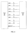
- a PoE cable typically consists of eight wires (wires 1 to 8), forming four pairs of twisted wires.
- Fig. 3 additionally depicts an optional 9 th conductor (shield wire 9), which is present in Shielded Twisted Pair systems. As shown in Fig. 3 the first twisted pair is formed by wire 1 and wire 2, the second twisted pair is formed by wire 3 and wire 4, the third twisted pair is formed by wire 5 and wire 6 and the fourth twisted pair is formed by wire 7 and wire 8.
- the resistance of wire 1 is R1
- the resistance of wire 2 is R2 carrying through to the resistance of wire 8 which is R8.
- the loop resistance is determined by measuring the resistance by the source unit 202, and then subtracting the resistance measured by the receive unit 204.
- the differential resistance of wire 1 and wire 2 can be determined by the loop resistance of wire 1 and wire 3 and the loop resistance of wire 2 and wire 3.
- the resistance of the loop formed by wire I and wire 3 R1+R3 is measured and the resistance of the loop formed by wire 2 and wire (R2+R3) is then substracted from this measurement.
- the differential resistance of wire 2 and wire 3 (R2-R3) can be determined by subtracting the loop resistance of wire 1 and wire 3 (R1+R3) from the loop resistance of wire 1 and wire 2 (R1+R2).
- the differential resistance of wire 3 and wire 1 (R3-R1) is determined by subtracting the loop resistance of wire 1 and wire 2 (R1+R2) from the the loop resistance of wire 2 and wire 3 (R2+R3):
- a computer processor preferably 102 compares the differential resistance as measured with reference to a threshold value. If the differential resistance exceeds the threshold value, the processor 102 preferably generates a resistance imbalance signal, which is sent to an output device 108 to indicate this condition to a user. Otherwise, if the differential resistance is below the threshold value, an indication is provided to a user, via preferably processor 102 and output device 108, indicating that the conductor qualifies for the desired service(s). For instance, such desired service can included (but is not to be understood to be limited thereto) to low-voltage DC power transmission.
- differential resistance can be determined by an average value of resistive components of the various loop-completing paths on the far-end tester, as shown in FIG. 4 .
- loop resistance (R3+R1) is the reverse current version of (R3+R1) and the loop resistance (R6+R1) is the reverse current version of (R1+R6).
- the differential resistance between wire 1 and wire 2 is an average value of the four sets resistance values measured.
- the four loop resistance measurement can also repeat, with the roles of the source and receive units reversed, so the final differential resistance value between wire 1 and wire 2 is an average value of 8 sets of measurements.
- resistance of wire 1(R1) can be determined by the differential resistance between wire 1 and wire 2 (R1-R2) and the loop resistance of wire 1 and wire 2 (R1+R2).
- resistance of wire 2 can be determined by the differential resistance between wire 2 and wire 3 (R2-R3) and the loop resistance of wire 2 and wire 3 (R2+R3). It is to be appreciated and understood that resistance of wire 4 to wire 8 is measured by the same method as described above. By this measurement method, resistance of each wire can be obtained. The processor 102 then preferably compares the resistance of each wire and resistance imbalance is determined by the comparison result.
- the resistance of each wire can also be determined by corresponding loop combinations.
- R ⁇ 2 1 / 2 * R ⁇ 2 + R ⁇ 3 - R ⁇ 1 + R ⁇ 3 + R ⁇ 1 + R ⁇ 2
- resistance for wire 1 (R1) is determined by measuring resistance between the first wire of the first wire pair (wire 1) and one reference wire chosen from the second wire pair (wire 3) to produce a first loop resistance measurement value (R1+R3), and resistance between a second wire of the first wire pair (wire 2) and the reference wire (wire 3) can be measured as a second loop resistance measurement value (R2
- the resistance of the first wire can be determined by calculating a resistance sum value by adding the third loop value (R1+R2) to a difference between the first and second loop values (R1+R3)-(R2+R3), and then the resistance sum value is divided in half to obtain a final resistance of wire 1 (R1). It is thus to be understood and appreciated that the resistance of each wire for the communication cable is determined in the similar method. It is to be further appreciated that the processor 102 then compares the resistance of each wire. Resistance imbalance is determined by the comparison result.
- a wire shield may be used as the reference wire if the cable is shielded.
- a higher current is applied, for instance, 8.57 ma.
- a lower current is applied, for instance, 0.5 ma.
- This current has to be more accurately controlled, so the differential resistance measurement algorithm assumes that the calibration of the main and remote unit is sufficiently accurate with either the main or the remote unit providing the measurement current.
- the present invention uses a loop resistance measurement system that is adapted to allow measurement of any two of the nine conductors connecting the main and remote units in a loopback configuration.
- the nine conductors are the 8 conductors for the 4 pairs, plus the shield, if there is one (cable can be shielded or unshielded).
- non-pair loops can be measured.
Landscapes
- Chemical & Material Sciences (AREA)
- Engineering & Computer Science (AREA)
- Computer Networks & Wireless Communication (AREA)
- Signal Processing (AREA)
- Life Sciences & Earth Sciences (AREA)
- General Health & Medical Sciences (AREA)
- Physics & Mathematics (AREA)
- Health & Medical Sciences (AREA)
- Chemical Kinetics & Catalysis (AREA)
- Analytical Chemistry (AREA)
- Biochemistry (AREA)
- Electrochemistry (AREA)
- General Physics & Mathematics (AREA)
- Immunology (AREA)
- Pathology (AREA)
- Measurement Of Resistance Or Impedance (AREA)
- Dc Digital Transmission (AREA)
- Cable Transmission Systems, Equalization Of Radio And Reduction Of Echo (AREA)
Applications Claiming Priority (1)
| Application Number | Priority Date | Filing Date | Title |
|---|---|---|---|
| US13/896,031 US9429534B2 (en) | 2013-05-16 | 2013-05-16 | Method and apparatus for determining wire resistance |
Publications (2)
| Publication Number | Publication Date |
|---|---|
| EP2804328A1 true EP2804328A1 (de) | 2014-11-19 |
| EP2804328B1 EP2804328B1 (de) | 2016-09-14 |
Family
ID=50771421
Family Applications (1)
| Application Number | Title | Priority Date | Filing Date |
|---|---|---|---|
| EP14168547.9A Active EP2804328B1 (de) | 2013-05-16 | 2014-05-15 | Verfahren und Vorrichtung zur Bestimmung von Drahtwiderstand |
Country Status (7)
| Country | Link |
|---|---|
| US (1) | US9429534B2 (de) |
| EP (1) | EP2804328B1 (de) |
| JP (1) | JP6499829B2 (de) |
| CN (1) | CN104168120B (de) |
| BR (1) | BR102014011545B1 (de) |
| CA (1) | CA2850197C (de) |
| ES (1) | ES2604603T3 (de) |
Cited By (1)
| Publication number | Priority date | Publication date | Assignee | Title |
|---|---|---|---|---|
| EP4057014A1 (de) * | 2017-02-28 | 2022-09-14 | AEM Singapore Pte. Ltd. | Mischmodus-vektornetzwerkanalysator |
Families Citing this family (4)
| Publication number | Priority date | Publication date | Assignee | Title |
|---|---|---|---|---|
| US10958471B2 (en) | 2018-04-05 | 2021-03-23 | Cisco Technology, Inc. | Method and apparatus for detecting wire fault and electrical imbalance for power over communications cabling |
| CN110082601A (zh) * | 2019-05-23 | 2019-08-02 | 中国电力科学研究院有限公司 | 一种用于测量电缆导体的交流电阻的装置及方法 |
| CN115792388A (zh) * | 2022-11-08 | 2023-03-14 | 国网电力科学研究院有限公司 | 一种消除耦合干扰的电缆导体交流电阻测试装置及方法 |
| CN120722070B (zh) * | 2025-08-22 | 2025-11-25 | 青岛艾诺仪器有限公司 | 一种线路电阻测量电路 |
Family Cites Families (11)
| Publication number | Priority date | Publication date | Assignee | Title |
|---|---|---|---|---|
| JPH06194401A (ja) * | 1992-04-01 | 1994-07-15 | Pentek Inc | 電線・ケーブル系統の異常検知装置 |
| US5559427A (en) * | 1994-04-04 | 1996-09-24 | Fluke Corporation | Instrument and method for testing local area network cables |
| JPH09102762A (ja) * | 1995-10-03 | 1997-04-15 | Nippon Telegr & Teleph Corp <Ntt> | 線路抵抗測定回路 |
| JP2001264376A (ja) * | 2000-03-17 | 2001-09-26 | Mitsubishi Electric Corp | ケーブル検査方法 |
| WO2005119759A1 (ja) * | 2004-06-01 | 2005-12-15 | Rohm Co., Ltd | 半導体装置および電子装置 |
| US7363562B2 (en) * | 2004-09-27 | 2008-04-22 | Synthesys Research Inc | Method and apparatus for deferred decision signal quality analysis |
| US7511515B2 (en) * | 2005-01-25 | 2009-03-31 | Linear Technology Corporation | System for providing power over communication cable having mechanism for determining resistance of communication cable |
| CN100507574C (zh) * | 2005-11-22 | 2009-07-01 | 旺矽科技股份有限公司 | 可传递差动信号对的探针卡 |
| CN201639854U (zh) * | 2009-11-30 | 2010-11-17 | 英业达股份有限公司 | 一种适用于测试高速信号线阻抗值的多层印刷电路板结构 |
| EP2378296B1 (de) * | 2010-04-19 | 2016-03-23 | ABB Technology AG | Verfahren und Anordnung zum Bestimmen von Impedanzwerten |
| US8823402B2 (en) * | 2011-11-23 | 2014-09-02 | Broadcom Corporation | Cable resistance determination in high-power PoE networks |
-
2013
- 2013-05-16 US US13/896,031 patent/US9429534B2/en active Active
-
2014
- 2014-04-29 CA CA2850197A patent/CA2850197C/en active Active
- 2014-05-13 BR BR102014011545-5A patent/BR102014011545B1/pt active IP Right Grant
- 2014-05-14 JP JP2014100067A patent/JP6499829B2/ja active Active
- 2014-05-15 CN CN201410204652.7A patent/CN104168120B/zh active Active
- 2014-05-15 EP EP14168547.9A patent/EP2804328B1/de active Active
- 2014-05-15 ES ES14168547.9T patent/ES2604603T3/es active Active
Non-Patent Citations (1)
| Title |
|---|
| "Measuring Resistance Imbalance Between Two Conductors of a Pair", 1 July 2002 (2002-07-01), pages 1 - 3, XP055133700, Retrieved from the Internet <URL:http://www.aemc.com/techinfo/appnotes/megohmmeters/APP-Megohm-TelephoneCables.pdf> [retrieved on 20140807] * |
Cited By (1)
| Publication number | Priority date | Publication date | Assignee | Title |
|---|---|---|---|---|
| EP4057014A1 (de) * | 2017-02-28 | 2022-09-14 | AEM Singapore Pte. Ltd. | Mischmodus-vektornetzwerkanalysator |
Also Published As
| Publication number | Publication date |
|---|---|
| JP2014225875A (ja) | 2014-12-04 |
| BR102014011545A2 (pt) | 2016-07-12 |
| ES2604603T3 (es) | 2017-03-07 |
| CN104168120A (zh) | 2014-11-26 |
| CA2850197C (en) | 2022-07-05 |
| US9429534B2 (en) | 2016-08-30 |
| JP6499829B2 (ja) | 2019-04-10 |
| EP2804328B1 (de) | 2016-09-14 |
| BR102014011545B1 (pt) | 2020-12-15 |
| CA2850197A1 (en) | 2014-11-16 |
| US20140340101A1 (en) | 2014-11-20 |
| CN104168120B (zh) | 2019-08-20 |
Similar Documents
| Publication | Publication Date | Title |
|---|---|---|
| EP2804328B1 (de) | Verfahren und Vorrichtung zur Bestimmung von Drahtwiderstand | |
| AU2017200861B2 (en) | Distributed antenna system using power-over-ethernet | |
| Cataliotti et al. | Oil-filled MV/LV power-transformer behavior in narrow-band power-line communication systems | |
| US9094339B2 (en) | Computer system communication channel diagnostics | |
| CN105049216B (zh) | 一种以太网供电方法及供电系统 | |
| TWI584611B (zh) | 乙太網路供電系統的受電裝置檢測裝置及方法 | |
| WO2009067898A1 (en) | Line measuring method and device | |
| CN114006632A (zh) | 一种地面电子单元leu的测试方法及系统 | |
| CN108446861B (zh) | 基于有向图排序的电力调度系统多源数据质量评价方法 | |
| US7697251B2 (en) | Powered communications interface with DC current imbalance compensation | |
| US9130854B2 (en) | Measurement method | |
| EP2769371B1 (de) | Zweikanaliger empfänger für stromleitungskommunikationen | |
| JP3217195U (ja) | 4線式測定ケーブル及びインピーダンス測定システム | |
| WO2023124592A1 (zh) | 基于逆黑盒及逆电磁对偶模型的pt一次电压重构方法 | |
| CN107064848A (zh) | 输电线路分布式故障诊断装置校验系统及方法 | |
| JP2017015450A (ja) | ケーブルの耐ノイズ特性評価方法及びペアケーブル選択方法 | |
| JP2807546B2 (ja) | 擬似通信回路網 | |
| CN105785214A (zh) | 一种简易网线测试仪 | |
| CN114024305B (zh) | 高压直流输电系统的50hz谐波放大倍数检测方法和装置 | |
| CN205484640U (zh) | 一种简易网线测试仪 | |
| CN118171431B (zh) | 一种智能二次线校线方法和系统 | |
| CN204989289U (zh) | 电网一次电流的测量装置 | |
| Kita et al. | Proposal of Instantaneous Power-Line Frequency Synchronized Superimposed Chart for Communications Quality Evaluation of broadband PLC System | |
| JP5647632B2 (ja) | 不平衡擬似回路網 | |
| Cepa et al. | Innovation of methods for measurement and modelling of twisted pair parameters |
Legal Events
| Date | Code | Title | Description |
|---|---|---|---|
| PUAI | Public reference made under article 153(3) epc to a published international application that has entered the european phase |
Free format text: ORIGINAL CODE: 0009012 |
|
| 17P | Request for examination filed |
Effective date: 20140515 |
|
| AK | Designated contracting states |
Kind code of ref document: A1 Designated state(s): AL AT BE BG CH CY CZ DE DK EE ES FI FR GB GR HR HU IE IS IT LI LT LU LV MC MK MT NL NO PL PT RO RS SE SI SK SM TR |
|
| AX | Request for extension of the european patent |
Extension state: BA ME |
|
| 17Q | First examination report despatched |
Effective date: 20150710 |
|
| GRAP | Despatch of communication of intention to grant a patent |
Free format text: ORIGINAL CODE: EPIDOSNIGR1 |
|
| INTG | Intention to grant announced |
Effective date: 20160304 |
|
| GRAJ | Information related to disapproval of communication of intention to grant by the applicant or resumption of examination proceedings by the epo deleted |
Free format text: ORIGINAL CODE: EPIDOSDIGR1 |
|
| GRAR | Information related to intention to grant a patent recorded |
Free format text: ORIGINAL CODE: EPIDOSNIGR71 |
|
| GRAS | Grant fee paid |
Free format text: ORIGINAL CODE: EPIDOSNIGR3 |
|
| GRAA | (expected) grant |
Free format text: ORIGINAL CODE: 0009210 |
|
| INTC | Intention to grant announced (deleted) | ||
| INTG | Intention to grant announced |
Effective date: 20160801 |
|
| AK | Designated contracting states |
Kind code of ref document: B1 Designated state(s): AL AT BE BG CH CY CZ DE DK EE ES FI FR GB GR HR HU IE IS IT LI LT LU LV MC MK MT NL NO PL PT RO RS SE SI SK SM TR |
|
| REG | Reference to a national code |
Ref country code: GB Ref legal event code: FG4D |
|
| REG | Reference to a national code |
Ref country code: CH Ref legal event code: EP |
|
| REG | Reference to a national code |
Ref country code: IE Ref legal event code: FG4D |
|
| REG | Reference to a national code |
Ref country code: AT Ref legal event code: REF Ref document number: 829998 Country of ref document: AT Kind code of ref document: T Effective date: 20161015 |
|
| REG | Reference to a national code |
Ref country code: DE Ref legal event code: R096 Ref document number: 602014003580 Country of ref document: DE |
|
| REG | Reference to a national code |
Ref country code: LT Ref legal event code: MG4D |
|
| REG | Reference to a national code |
Ref country code: NL Ref legal event code: MP Effective date: 20160914 |
|
| PG25 | Lapsed in a contracting state [announced via postgrant information from national office to epo] |
Ref country code: FI Free format text: LAPSE BECAUSE OF FAILURE TO SUBMIT A TRANSLATION OF THE DESCRIPTION OR TO PAY THE FEE WITHIN THE PRESCRIBED TIME-LIMIT Effective date: 20160914 Ref country code: LT Free format text: LAPSE BECAUSE OF FAILURE TO SUBMIT A TRANSLATION OF THE DESCRIPTION OR TO PAY THE FEE WITHIN THE PRESCRIBED TIME-LIMIT Effective date: 20160914 Ref country code: NO Free format text: LAPSE BECAUSE OF FAILURE TO SUBMIT A TRANSLATION OF THE DESCRIPTION OR TO PAY THE FEE WITHIN THE PRESCRIBED TIME-LIMIT Effective date: 20161214 Ref country code: HR Free format text: LAPSE BECAUSE OF FAILURE TO SUBMIT A TRANSLATION OF THE DESCRIPTION OR TO PAY THE FEE WITHIN THE PRESCRIBED TIME-LIMIT Effective date: 20160914 Ref country code: RS Free format text: LAPSE BECAUSE OF FAILURE TO SUBMIT A TRANSLATION OF THE DESCRIPTION OR TO PAY THE FEE WITHIN THE PRESCRIBED TIME-LIMIT Effective date: 20160914 |
|
| REG | Reference to a national code |
Ref country code: AT Ref legal event code: MK05 Ref document number: 829998 Country of ref document: AT Kind code of ref document: T Effective date: 20160914 |
|
| PG25 | Lapsed in a contracting state [announced via postgrant information from national office to epo] |
Ref country code: GR Free format text: LAPSE BECAUSE OF FAILURE TO SUBMIT A TRANSLATION OF THE DESCRIPTION OR TO PAY THE FEE WITHIN THE PRESCRIBED TIME-LIMIT Effective date: 20161215 Ref country code: LV Free format text: LAPSE BECAUSE OF FAILURE TO SUBMIT A TRANSLATION OF THE DESCRIPTION OR TO PAY THE FEE WITHIN THE PRESCRIBED TIME-LIMIT Effective date: 20160914 Ref country code: NL Free format text: LAPSE BECAUSE OF FAILURE TO SUBMIT A TRANSLATION OF THE DESCRIPTION OR TO PAY THE FEE WITHIN THE PRESCRIBED TIME-LIMIT Effective date: 20160914 Ref country code: SE Free format text: LAPSE BECAUSE OF FAILURE TO SUBMIT A TRANSLATION OF THE DESCRIPTION OR TO PAY THE FEE WITHIN THE PRESCRIBED TIME-LIMIT Effective date: 20160914 |
|
| REG | Reference to a national code |
Ref country code: ES Ref legal event code: FG2A Ref document number: 2604603 Country of ref document: ES Kind code of ref document: T3 Effective date: 20170307 |
|
| PG25 | Lapsed in a contracting state [announced via postgrant information from national office to epo] |
Ref country code: RO Free format text: LAPSE BECAUSE OF FAILURE TO SUBMIT A TRANSLATION OF THE DESCRIPTION OR TO PAY THE FEE WITHIN THE PRESCRIBED TIME-LIMIT Effective date: 20160914 Ref country code: EE Free format text: LAPSE BECAUSE OF FAILURE TO SUBMIT A TRANSLATION OF THE DESCRIPTION OR TO PAY THE FEE WITHIN THE PRESCRIBED TIME-LIMIT Effective date: 20160914 |
|
| REG | Reference to a national code |
Ref country code: FR Ref legal event code: PLFP Year of fee payment: 4 |
|
| PG25 | Lapsed in a contracting state [announced via postgrant information from national office to epo] |
Ref country code: SM Free format text: LAPSE BECAUSE OF FAILURE TO SUBMIT A TRANSLATION OF THE DESCRIPTION OR TO PAY THE FEE WITHIN THE PRESCRIBED TIME-LIMIT Effective date: 20160914 Ref country code: IS Free format text: LAPSE BECAUSE OF FAILURE TO SUBMIT A TRANSLATION OF THE DESCRIPTION OR TO PAY THE FEE WITHIN THE PRESCRIBED TIME-LIMIT Effective date: 20170114 Ref country code: BG Free format text: LAPSE BECAUSE OF FAILURE TO SUBMIT A TRANSLATION OF THE DESCRIPTION OR TO PAY THE FEE WITHIN THE PRESCRIBED TIME-LIMIT Effective date: 20161214 Ref country code: CZ Free format text: LAPSE BECAUSE OF FAILURE TO SUBMIT A TRANSLATION OF THE DESCRIPTION OR TO PAY THE FEE WITHIN THE PRESCRIBED TIME-LIMIT Effective date: 20160914 Ref country code: PT Free format text: LAPSE BECAUSE OF FAILURE TO SUBMIT A TRANSLATION OF THE DESCRIPTION OR TO PAY THE FEE WITHIN THE PRESCRIBED TIME-LIMIT Effective date: 20170116 Ref country code: PL Free format text: LAPSE BECAUSE OF FAILURE TO SUBMIT A TRANSLATION OF THE DESCRIPTION OR TO PAY THE FEE WITHIN THE PRESCRIBED TIME-LIMIT Effective date: 20160914 Ref country code: AT Free format text: LAPSE BECAUSE OF FAILURE TO SUBMIT A TRANSLATION OF THE DESCRIPTION OR TO PAY THE FEE WITHIN THE PRESCRIBED TIME-LIMIT Effective date: 20160914 Ref country code: SK Free format text: LAPSE BECAUSE OF FAILURE TO SUBMIT A TRANSLATION OF THE DESCRIPTION OR TO PAY THE FEE WITHIN THE PRESCRIBED TIME-LIMIT Effective date: 20160914 Ref country code: BE Free format text: LAPSE BECAUSE OF FAILURE TO SUBMIT A TRANSLATION OF THE DESCRIPTION OR TO PAY THE FEE WITHIN THE PRESCRIBED TIME-LIMIT Effective date: 20160914 |
|
| REG | Reference to a national code |
Ref country code: DE Ref legal event code: R097 Ref document number: 602014003580 Country of ref document: DE |
|
| PG25 | Lapsed in a contracting state [announced via postgrant information from national office to epo] |
Ref country code: IT Free format text: LAPSE BECAUSE OF FAILURE TO SUBMIT A TRANSLATION OF THE DESCRIPTION OR TO PAY THE FEE WITHIN THE PRESCRIBED TIME-LIMIT Effective date: 20160914 |
|
| PLBE | No opposition filed within time limit |
Free format text: ORIGINAL CODE: 0009261 |
|
| STAA | Information on the status of an ep patent application or granted ep patent |
Free format text: STATUS: NO OPPOSITION FILED WITHIN TIME LIMIT |
|
| PG25 | Lapsed in a contracting state [announced via postgrant information from national office to epo] |
Ref country code: DK Free format text: LAPSE BECAUSE OF FAILURE TO SUBMIT A TRANSLATION OF THE DESCRIPTION OR TO PAY THE FEE WITHIN THE PRESCRIBED TIME-LIMIT Effective date: 20160914 |
|
| 26N | No opposition filed |
Effective date: 20170615 |
|
| PG25 | Lapsed in a contracting state [announced via postgrant information from national office to epo] |
Ref country code: LU Free format text: LAPSE BECAUSE OF NON-PAYMENT OF DUE FEES Effective date: 20170531 |
|
| PG25 | Lapsed in a contracting state [announced via postgrant information from national office to epo] |
Ref country code: SI Free format text: LAPSE BECAUSE OF FAILURE TO SUBMIT A TRANSLATION OF THE DESCRIPTION OR TO PAY THE FEE WITHIN THE PRESCRIBED TIME-LIMIT Effective date: 20160914 |
|
| REG | Reference to a national code |
Ref country code: CH Ref legal event code: PL |
|
| PG25 | Lapsed in a contracting state [announced via postgrant information from national office to epo] |
Ref country code: MC Free format text: LAPSE BECAUSE OF FAILURE TO SUBMIT A TRANSLATION OF THE DESCRIPTION OR TO PAY THE FEE WITHIN THE PRESCRIBED TIME-LIMIT Effective date: 20160914 |
|
| REG | Reference to a national code |
Ref country code: IE Ref legal event code: MM4A |
|
| PG25 | Lapsed in a contracting state [announced via postgrant information from national office to epo] |
Ref country code: LI Free format text: LAPSE BECAUSE OF NON-PAYMENT OF DUE FEES Effective date: 20170531 Ref country code: CH Free format text: LAPSE BECAUSE OF NON-PAYMENT OF DUE FEES Effective date: 20170531 |
|
| PG25 | Lapsed in a contracting state [announced via postgrant information from national office to epo] |
Ref country code: LU Free format text: LAPSE BECAUSE OF NON-PAYMENT OF DUE FEES Effective date: 20170515 |
|
| PG25 | Lapsed in a contracting state [announced via postgrant information from national office to epo] |
Ref country code: IE Free format text: LAPSE BECAUSE OF NON-PAYMENT OF DUE FEES Effective date: 20170515 |
|
| REG | Reference to a national code |
Ref country code: FR Ref legal event code: PLFP Year of fee payment: 5 |
|
| PG25 | Lapsed in a contracting state [announced via postgrant information from national office to epo] |
Ref country code: MT Free format text: LAPSE BECAUSE OF NON-PAYMENT OF DUE FEES Effective date: 20170515 |
|
| PG25 | Lapsed in a contracting state [announced via postgrant information from national office to epo] |
Ref country code: AL Free format text: LAPSE BECAUSE OF FAILURE TO SUBMIT A TRANSLATION OF THE DESCRIPTION OR TO PAY THE FEE WITHIN THE PRESCRIBED TIME-LIMIT Effective date: 20160914 |
|
| PG25 | Lapsed in a contracting state [announced via postgrant information from national office to epo] |
Ref country code: HU Free format text: LAPSE BECAUSE OF FAILURE TO SUBMIT A TRANSLATION OF THE DESCRIPTION OR TO PAY THE FEE WITHIN THE PRESCRIBED TIME-LIMIT; INVALID AB INITIO Effective date: 20140515 |
|
| PG25 | Lapsed in a contracting state [announced via postgrant information from national office to epo] |
Ref country code: CY Free format text: LAPSE BECAUSE OF FAILURE TO SUBMIT A TRANSLATION OF THE DESCRIPTION OR TO PAY THE FEE WITHIN THE PRESCRIBED TIME-LIMIT Effective date: 20160914 |
|
| PG25 | Lapsed in a contracting state [announced via postgrant information from national office to epo] |
Ref country code: MK Free format text: LAPSE BECAUSE OF FAILURE TO SUBMIT A TRANSLATION OF THE DESCRIPTION OR TO PAY THE FEE WITHIN THE PRESCRIBED TIME-LIMIT Effective date: 20160914 |
|
| PG25 | Lapsed in a contracting state [announced via postgrant information from national office to epo] |
Ref country code: TR Free format text: LAPSE BECAUSE OF FAILURE TO SUBMIT A TRANSLATION OF THE DESCRIPTION OR TO PAY THE FEE WITHIN THE PRESCRIBED TIME-LIMIT Effective date: 20160914 |
|
| PGFP | Annual fee paid to national office [announced via postgrant information from national office to epo] |
Ref country code: DE Payment date: 20250528 Year of fee payment: 12 |
|
| PGFP | Annual fee paid to national office [announced via postgrant information from national office to epo] |
Ref country code: GB Payment date: 20250520 Year of fee payment: 12 Ref country code: ES Payment date: 20250611 Year of fee payment: 12 |
|
| PGFP | Annual fee paid to national office [announced via postgrant information from national office to epo] |
Ref country code: FR Payment date: 20250526 Year of fee payment: 12 |