EP2804450A2 - Pièce isolante en une ou plusieurs parties pour une torche à plasma, notamment une torche de coupe au plasma et agencements et torche à plasma dotés de celle-ci - Google Patents
Pièce isolante en une ou plusieurs parties pour une torche à plasma, notamment une torche de coupe au plasma et agencements et torche à plasma dotés de celle-ci Download PDFInfo
- Publication number
- EP2804450A2 EP2804450A2 EP13004796.2A EP13004796A EP2804450A2 EP 2804450 A2 EP2804450 A2 EP 2804450A2 EP 13004796 A EP13004796 A EP 13004796A EP 2804450 A2 EP2804450 A2 EP 2804450A2
- Authority
- EP
- European Patent Office
- Prior art keywords
- nozzle
- plasma
- conductive
- heat
- nozzle cap
- Prior art date
- Legal status (The legal status is an assumption and is not a legal conclusion. Google has not performed a legal analysis and makes no representation as to the accuracy of the status listed.)
- Granted
Links
Images











Classifications
-
- H—ELECTRICITY
- H05—ELECTRIC TECHNIQUES NOT OTHERWISE PROVIDED FOR
- H05H—PLASMA TECHNIQUE; PRODUCTION OF ACCELERATED ELECTRICALLY-CHARGED PARTICLES OR OF NEUTRONS; PRODUCTION OR ACCELERATION OF NEUTRAL MOLECULAR OR ATOMIC BEAMS
- H05H1/00—Generating plasma; Handling plasma
- H05H1/24—Generating plasma
- H05H1/26—Plasma torches
- H05H1/32—Plasma torches using an arc
- H05H1/34—Details, e.g. electrodes, nozzles
-
- H—ELECTRICITY
- H05—ELECTRIC TECHNIQUES NOT OTHERWISE PROVIDED FOR
- H05H—PLASMA TECHNIQUE; PRODUCTION OF ACCELERATED ELECTRICALLY-CHARGED PARTICLES OR OF NEUTRONS; PRODUCTION OR ACCELERATION OF NEUTRAL MOLECULAR OR ATOMIC BEAMS
- H05H1/00—Generating plasma; Handling plasma
- H05H1/24—Generating plasma
- H05H1/26—Plasma torches
- H05H1/32—Plasma torches using an arc
- H05H1/34—Details, e.g. electrodes, nozzles
- H05H1/3436—Hollow cathodes with internal coolant flow
-
- H—ELECTRICITY
- H05—ELECTRIC TECHNIQUES NOT OTHERWISE PROVIDED FOR
- H05H—PLASMA TECHNIQUE; PRODUCTION OF ACCELERATED ELECTRICALLY-CHARGED PARTICLES OR OF NEUTRONS; PRODUCTION OR ACCELERATION OF NEUTRAL MOLECULAR OR ATOMIC BEAMS
- H05H7/00—Details of devices of the types covered by groups H05H9/00, H05H11/00, H05H13/00
- H05H7/001—Arrangements for beam delivery or irradiation
-
- H—ELECTRICITY
- H05—ELECTRIC TECHNIQUES NOT OTHERWISE PROVIDED FOR
- H05H—PLASMA TECHNIQUE; PRODUCTION OF ACCELERATED ELECTRICALLY-CHARGED PARTICLES OR OF NEUTRONS; PRODUCTION OR ACCELERATION OF NEUTRAL MOLECULAR OR ATOMIC BEAMS
- H05H1/00—Generating plasma; Handling plasma
- H05H1/24—Generating plasma
- H05H1/26—Plasma torches
- H05H1/32—Plasma torches using an arc
- H05H1/34—Details, e.g. electrodes, nozzles
- H05H1/3442—Cathodes with inserted tip
-
- H—ELECTRICITY
- H05—ELECTRIC TECHNIQUES NOT OTHERWISE PROVIDED FOR
- H05H—PLASMA TECHNIQUE; PRODUCTION OF ACCELERATED ELECTRICALLY-CHARGED PARTICLES OR OF NEUTRONS; PRODUCTION OR ACCELERATION OF NEUTRAL MOLECULAR OR ATOMIC BEAMS
- H05H1/00—Generating plasma; Handling plasma
- H05H1/24—Generating plasma
- H05H1/26—Plasma torches
- H05H1/32—Plasma torches using an arc
- H05H1/34—Details, e.g. electrodes, nozzles
- H05H1/3457—Nozzle protection devices
Definitions
- the present invention relates to a mono- or multi-part insulating part for a plasma torch, in particular a plasma cutting torch, for electrical insulation between at least two electrically conductive components of the plasma torch, arrangements and plasma torch with such an insulating part, plasma torch with such an arrangement and method for machining a workpiece a thermal plasma, plasma cutting and plasma welding.
- Plasma torches are generally used for the thermal processing of electrically conductive materials, such as steel and non-ferrous metals.
- Plasma welding torches are used for welding and plasma cutting torches for cutting electrically conductive materials such as steel and non-ferrous metals.
- Plasma torches usually consist of a torch body, an electrode, a nozzle and a holder for it. Modern plasma torches also have a nozzle cap mounted above the nozzle. Often a nozzle is fixed by means of a nozzle cap.
- the components which wear out due to the high thermal load caused by the operation of the plasma torch are, in particular, the electrode, the nozzle, the nozzle cap, the nozzle protection cap Nozzle cap holder and the plasma gas guide and secondary gas guide parts. These components can be easily changed by an operator and thus be referred to as wear parts.
- the plasma torches are connected via lines to a power source and a gas supply, which supply the plasma torch. Furthermore, the plasma torch may be connected to a cooling means for a cooling medium, such as a cooling liquid.
- Plasma cutting torches are subject to particularly high thermal loads. This is due to the strong constriction of the plasma jet through the nozzle bore. In comparison to plasma welding, small holes are used in relation to the cutting current, so that high current densities of 50 to 150 A / mm 2 in the nozzle bore, high energy densities of approx. 2x10 6 W / cm 2 and high temperatures of up to 30,000 K are generated , Furthermore, in the plasma cutting torch higher gas pressures, usually up to 12 bar, used. The combination of high temperature and high kinetic energy of the plasma gas flowing through the nozzle bore leads to melting of the workpiece and expulsion of the melt. The result is a kerf and the workpiece is separated. In plasma cutting, oxidizing gases are often used to cut unalloyed steels. This also leads to a high thermal load on the wearing parts and the plasma cutting torch.
- the plasma gas is passed through a gas guide part, which may also be multi-part. As a result, the plasma gas can be targeted. Often it is offset by a radial and / or axial displacement of the openings in the plasma gas guide part in rotation about the electrode.
- the plasma gas guide member is made of electrically insulating material because of the electrode and the nozzle must be electrically insulated from each other. This is necessary because the electrode and the nozzle have different electrical potentials during operation of the plasma cutting torch. To operate the plasma cutting torch, an arc is generated between the electrode and the nozzle and / or the workpiece which ionizes the plasma gas.
- a high voltage can be applied between the electrode and the nozzle, which ensures a pre-ionization of the distance between the electrode and nozzle and thus the formation of an arc.
- the arc burning between the electrode and the nozzle is also called a pilot arc.
- the pilot arc exits through the nozzle bore and strikes the workpiece, ionizing the distance to the workpiece. As a result, the arc can form between the electrode and the workpiece. This arc is also called the main arc.
- the pilot arc can be switched off. But he can also continue to operate. In plasma cutting, this is often switched off so as not to burden the nozzle even more.
- the electrode and the nozzle are subjected to high thermal stress and must be cooled. At the same time, they must also conduct the electrical current needed to form the arc. Therefore, for good heat and electrically conductive materials, usually metals, for example copper, silver, aluminum, tin, zinc, iron or alloys, in which at least one of these metals is included, are used.
- the electrode often consists of an electrode holder and an emissive insert made of a material having a high melting temperature (> 2000 ° C) and a lower electron work function than the electrode holder.
- materials for the emission use when non-oxidizing plasma gases, such as argon, hydrogen, nitrogen, helium and mixtures thereof, tungsten and the use of oxidizing gases, such as oxygen, air and mixtures thereof, nitrogen-oxygen mixture and mixtures used with other gases, hafnium or zirconium.
- the high-temperature material can be fitted into an electrode holder, which consists of good heat and good electrical conductivity material, for example, be pressed with positive and / or adhesion.
- the cooling of the electrode and nozzle can be effected by gas, for example the plasma gas or a secondary gas flowing along the outside of the nozzle. More effective, however, is the cooling with a liquid, for example water.
- the electrode and / or nozzle are often cooled directly with the liquid, i. the liquid is in direct contact with the electrode and / or the nozzle.
- To guide the cooling liquid around the nozzle there is a nozzle cap around the nozzle, the inner surface of which forms with the outer surface of the nozzle a coolant space in which the coolant flows.
- a secondary or inert gas exits the bore of the nozzle cap and envelops the plasma jet and provides for a defined atmosphere around it.
- the secondary gas protects the nozzle and the nozzle cap from arcs that may form between it and the workpiece. These are called double arcs and can damage the nozzle.
- the nozzle and the nozzle cap are heavily loaded by hot high-spraying of material.
- the secondary gas whose volume flow during piercing can be increased compared to the value during cutting, keeps the high-spraying material away from the nozzle and the nozzle cap and thus protects against damage.
- the nozzle cap is also subjected to high thermal loads and must be cooled. Therefore, for good heat and electrically conductive materials, usually metals, for example copper, silver, aluminum, tin, zinc, iron or alloys, in which at least one of these metals is included, are used.
- metals for example copper, silver, aluminum, tin, zinc, iron or alloys, in which at least one of these metals is included, are used.
- the electrode and the nozzle can also be cooled indirectly. They stand with a component which consists of a good heat and good electrical conductivity material, usually a metal, for example copper, silver, aluminum, tin, zinc, iron or alloys in which at least one of these metals is included , by contact in contact. This component in turn is cooled directly, that is, it is in direct contact with the most-flowing coolant. These components can simultaneously serve as a holder or receptacle for the electrode, the nozzle, the nozzle cap or the nozzle cap and remove the heat and the current.
- a component which consists of a good heat and good electrical conductivity material usually a metal, for example copper, silver, aluminum, tin, zinc, iron or alloys in which at least one of these metals is included , by contact in contact.
- This component in turn is cooled directly, that is, it is in direct contact with the most-flowing coolant.
- These components can simultaneously serve as a holder or receptacle for the electrode, the
- the nozzle cap is usually cooled only by the secondary gas. Arrangements are also known in which the nozzle protection cap is cooled directly or indirectly by a cooling liquid.
- the gas cooling (plasma gas and / or secondary gas cooling) has the disadvantage that it is not effective and the required gas flow rate is very high in order to achieve acceptable cooling or heat dissipation.
- Plasma cutting torches with water cooling require, for example, gas flow rates of 500 l / h to 4000 l / h, while plasma cutting torches without water cooling require gas flow rates of 5000 to 11000 l / h. These ranges are a function of the cutting currents used, which may, for example, be in a range of 20 to 600 A.
- the volume flow of the plasma gas and / or secondary gas should be selected so that the best cutting results are achieved. Too large volume flows, which are necessary for the cooling but often worsen the cutting result.
- the invention is therefore based on the object to provide for more effective cooling of components, in particular wear parts, a plasma torch.
- this object is achieved by a single- or multi-part insulating part for a plasma torch, in particular a plasma cutting torch, for electrical insulation between at least two electrically conductive components of the plasma torch, characterized in that it consists of an electrically non-conductive and heat-conducting material or at least a part of which consists of an electrically non-conductive and heat-conductive material.
- the expression "electrically non-conductive” should also include that the material of the plasma torch insulating part conducts electricity slightly or negligibly.
- the insulating part may, for example, be a plasma gas guide part, secondary gas guide part or cooling gas guide part.
- this object is achieved according to a second aspect by an arrangement of an electrode and / or a nozzle and / or a nozzle cap and / or a nozzle cap and / or a nozzle cap holder for a plasma torch, in particular a plasma cutting torch, and an insulating part according to one of claims 1 to 12.
- this object is achieved by an arrangement comprising a receptacle for a nozzle cap holder and a nozzle cap holder for a plasma torch, in particular a plasma cutting torch, characterized in that the receptacle as a preferably in direct contact with the Düsenschutzkappenhalterung insulating part according to one of claims 1 to 12 is formed.
- the receptacle and the nozzle cap holder can be connected by a thread.
- this object is achieved by an arrangement of an electrode and a nozzle for a plasma torch, in particular a plasma cutting torch, characterized in that between the electrode and the nozzle designed as a plasma gas guide part insulating part according to one of claims 1 to 12, preferably in direct contact with the same, is arranged.
- this object is achieved according to a further aspect by an arrangement of a nozzle and a nozzle cap for a plasma torch, in particular a plasma cutting torch, characterized in that between the nozzle and the nozzle cap designed as a secondary gas guide member insulating member according to any one of claims 1 to 12, preferably in direct contact with selbigem, is arranged.
- this object is achieved by an arrangement of a nozzle cap and a nozzle cap for a plasma torch, in particular a plasma cutting torch, characterized in that between the nozzle cap and the nozzle cap as an insulating part according to one of claims 1 to 12, preferably in direct contact with the same, is arranged dissolved.
- the present invention provides a plasma torch, in particular plasma cutting torch, comprising at least one insulating part according to one of claims 1 to 12.
- the present invention provides a plasma torch, in particular plasma cutting torch, comprising at least one arrangement according to one of claims 13 to 18 and a method according to claim 24.
- the insulating part can be provided that it consists of at least two parts, wherein one of the parts of an electrically non-conductive and highly heat-conductive material and the other or at least one of the parts of an electrically non-conductive and non-heat conducting material.
- the part of an electrically non-conductive and heat-conductive material has at least one surface acting as a contact surface, which is flush with an immediately adjacent surface of the part of an electrically non-conductive and non-heat conducting material or protrudes beyond this ,
- the insulating part consists of at least two parts, wherein one of the parts of a highly electrically conductive and highly heat-conductive material and the other or at least another of the parts of an electrically non-conductive and heat-conductive material.
- the insulating part consists of at least three parts, wherein one of the parts of a highly electrically conductive and highly heat-conductive material, another of the parts of an electrically non-suffering and heat-conductive material and another of the parts of a electrically non-conductive and heat non-conductive material.
- the electrically non-conductive and heat-conductive material has a thermal conductivity of at least 40 W / (m * K), preferably at least 60 W / (m * K) and more preferably at least 90 W / (m * K), more preferably at least 120 W / (m * K), more preferably at least 150 W / (m * K) and even more preferably at least 180 W / (m * K).
- the electrically non-conductive and heat-conductive material and / or the electrically non-conductive and non-conductive material has a specific electrical resistance of at least 10 6 ⁇ * cm, preferably at least 10 10 ⁇ * cm, and / or a voltage breakdown strength of at least 7 kV / mm, preferably at least 10 kV / mm.
- the electrically non-conductive and heat-conducting material is a ceramic, preferably from the group of nitride ceramics, in particular aluminum nitride, boron nitride and silicon nitride ceramics, carbide ceramics, in particular silicon carbide ceramics, oxide ceramics, in particular alumina, zirconium oxide and beryllium oxide ceramics , and the silicate ceramics, or plastic, for example, plastic film.
- nitride ceramics in particular aluminum nitride, boron nitride and silicon nitride ceramics
- carbide ceramics in particular silicon carbide ceramics
- oxide ceramics in particular alumina, zirconium oxide and beryllium oxide ceramics
- plastic for example, plastic film.
- an electrically non-conductive and heat-conductive material for. As ceramic, and another electrically non-conductive material, for. As plastic, in a material, a so-called compound material to use.
- a so-called compound material can be produced, for example, from powder of both materials by sintering.
- this compound material must be electrically non-conductive and heat good conductive.
- the electrically non-conductive and non-conductive material has a thermal conductivity of at most 1 (W / m * K).
- the parts are positively or non-positively connected by gluing or by a thermal process, for example soldering or welding.
- the insulating part has at least one opening and / or at least one recess and / or at least one groove. This may be the case, for example, when the insulating part is a gas guide part, such as a plasma gas or secondary gas guide part.
- the at least one opening and / or the at least one recess and / or the at least one groove in the electrically non-conductive and heat-conducting material and / or electrically non-conductive and non-heat conducting material and / or electrically well conductive and heat well conductive material is located / located.
- the insulating part is designed to guide a gas, in particular a plasma, secondary or cooling gas.
- the insulating part is in direct contact with the electrode and / or the nozzle and / or the nozzle cap and / or the nozzle protection cap and / or the nozzle protection cap holder.
- the insulating part with the electrode and / or the nozzle and / or the nozzle cap and / or the nozzle cap and / or nozzle protective cap holder positively and / or non-positively, by gluing or by a thermal process, for example, soldering and welding, connected.
- the insulating part or a material which is electrically nonconductive and conducts heat well existing part of the same at least one surface acting as a contact surface, preferably two surfaces, which is in direct contact at least with a surface of a highly electrically conductive component, in particular an electrode, nozzle, nozzle cap, nozzle cap or nozzle cap holder, the plasma torch.
- the insulating part or a part consisting of electrically nonconducting and heat-conducting material has at least two surfaces acting as contact surfaces, at least with a surface of a highly electrically conductive component, in particular an electrode, nozzle, nozzle cap, Nozzle protection cap or nozzle cap holder, the plasma torch and another surface of another electrically good conductive component of the plasma torch is in direct contact.
- the insulating part is a gas guide part, in particular a plasma gas, secondary gas or cooling gas guide part.
- the insulating part has at least one surface which, during operation, has direct contact with a cooling medium, preferably a liquid and / or a gas and / or a liquid-gas mixture.
- a cooling medium preferably a liquid and / or a gas and / or a liquid-gas mixture.
- the laser may be a fiber laser, diode reader and / or diode-pumped laser.
- the invention is based on the surprising finding that by using a material which not only does not conduct electricity electrically but also conducts heat well, a more effective one and cost-effective cooling is possible and smaller and simpler designs of plasma torches are possible and lower temperature differences and thus lower mechanical stresses can be achieved.
- the invention provides cooling, at least in one or more particular embodiments, of components, particularly consumables, of a plasma torch that is more effective and / or less expensive and / or results in lower mechanical stresses and / or enables smaller and / or simpler plasma torch designs to simultaneously provide electrical isolation between components of a plasma torch.
- FIG. 1 shows a liquid-cooled plasma cutting torch 1 according to a particular embodiment of the present invention. It comprises an electrode 2, an insulating part designed as a plasma gas guide part 3 for guiding plasma gas PG and a nozzle 4.
- the electrode 2 consists of an electrode holder 2.1 and an emissive insert 2.2.
- the electrode holder 2.2 consists of a good electrical and heat well conductive material, here of a metal, for example copper, silver, aluminum or an alloy in which at least one of these metals is included.
- the emissive insert 2.2 is made of a material having a high melting temperature (> 2000 ° C).
- the emission insert 2.2 is introduced into the electrode holder 2.1.
- the electrode 2 is shown here as a flat electrode, in which the emission insert 2.2 does not protrude beyond the surface of the front end of the electrode holder 2.1.
- the electrode 2 protrudes into the hollow interior 4.2 of the nozzle 4.
- the nozzle is screwed with a thread 4.20 in a nozzle holder 6 with internal thread 6.20.
- the plasma gas guide part 3 is arranged between the nozzle 4 and the electrode 2.
- Plasma gas guide part 3 are bores, openings, grooves and / or recesses (not shown), through which the plasma gas PG flows.
- the plasma gas PG can be set in rotation. It serves to stabilize the arc or the plasma jet.
- the arc burns between the emissive insert 2.2 and a workpiece (not shown) and is constricted by a nozzle bore 4.1.
- the arc itself already has a high temperature, which is further increased by its constriction. Temperatures of up to 30,000 K are specified. Therefore, the electrode 2 and the nozzle 4 are cooled with a cooling medium.
- a cooling medium a liquid, in the simplest case water, a gas, in the simplest case, air or a mixture thereof, in the simplest case, an air-water mixture, which is referred to as aerosol, are used. Liquid cooling is considered to be the most effective.
- a cooling tube 10 through which the coolant from the coolant flow WV2 through the coolant space 10.10 to the electrode 2 towards the near the emission insert 2.2 and through the space from the outer surface of the cooling tube 10 in the inner surface of the Electrode 2 is formed, is returned to the coolant return WR2.
- the nozzle 4 is cooled indirectly via the nozzle holder 6, to which the coolant is led away again by a coolant space 6.10 (WV1) and via a coolant space 6.11 (WR1).
- the coolant usually flows at a volume flow of 1 to 10 l / min.
- the nozzle 4 and the nozzle holder 6 are made of a metal.
- the formed as a plasma gas guide part 3 insulating part is formed in one piece in this example and consists of an electrically non-conductive and heat-conducting material.
- an electrical insulation between the electrode 2 and the nozzle 4 is achieved. This is necessary for the operation of the plasma cutting torch 1, namely the high-voltage ignition and the operation of a pilot arc burning between the electrode 2 and the nozzle 4.
- heat is conducted between the electrode 2 and the nozzle 4 from the warmer to the colder component through the heat well-conducting designed as a plasma gas guide part 3 insulating member. There is thus an additional heat exchange via the insulating part.
- the plasma gas guide member 3 is in contact with the electrode 2 and the nozzle 4 by contact via contact surfaces.
- a contact surface 2.3 is, for example, a cylindrical outer surface of the electrode 2 and a contact surface 3.5 is a cylindrical inner surface of the plasma gas-conducting part 3.
- a contact surface 3.6 is a cylindrical outer surface of the plasma gas-conducting part 3, and a contact surface 4.3 is a cylindrical inner surface of the nozzle 4.
- a clearance with little play for example, H7 / h6 used according to DIN EN ISO 286 between the cylindrical inner and outer surfaces, on the one hand to nesting and on the other hand a good contact and thus low thermal resistance and thus to realize good heat transfer.
- the heat transfer can be improved by applying thermal paste to these contact surfaces.
- the nozzle 4 and the plasma gas guide part 3 each have a contact surface 4.5 and 3.7, which are annular surfaces here and are in contact with each other by contact. It is a frictional connection between the annular surfaces, which is realized by screwing the nozzle 4 in the nozzle holder 6.
- a ceramic material is used here by way of example.
- Particularly suitable aluminum nitride, which according to DIN 60672 has a very good thermal conductivity (about 180 W / (m * K) and a high electrical resistivity (about 10 12 ⁇ * cm).
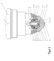
- FIG. 2 a cylindrical plasma cutting torch 1 is shown, in which the electrode 2 is cooled directly with coolant.
- the cooling of the nozzle 4 is carried out by heat conduction via a formed as a plasma gas guide part 3 insulating part to the cooled directly with coolant electrode 2 out.
- a formed as a plasma gas guide part 3 insulating part to the cooled directly with coolant electrode 2 out.
- the electrical insulation between the electrode 2 and the nozzle 4 is achieved. This is necessary for the operation of the plasma cutting torch 1, namely the high-voltage ignition and the operation of the burning between the electrode 2 and the nozzle 4 pilot arc.
- a contact surface 2.3 is, for example, a cylindrical outer surface of the electrode 2 and a contact surface 3.5 is a cylindrical inner surface of the plasma gas-conducting part 3.
- a contact surface 3.6 is a cylindrical outer surface of the plasma gas-conducting part 3, and a contact surface 4.3 is a cylindrical inner surface of the nozzle 4.
- a clearance with little play for example, H7 / h6 according to DIN EN ISO 286 between the cylindrical inner and outer surfaces used to on the one hand the nesting and on the other hand a good contact and thus low heat resistance and thus to realize good heat transfer.
- the heat transfer can be improved by applying thermal paste to these contact surfaces. Then a fit with a larger game, for example H7 / g6 can be used.
- the nozzle 4 and the plasma gas guide part 3 here each have a contact surface 4.5 or 3.7, which are annular surfaces here and are in contact with each other by contact. It is a frictional connection between the annular surfaces, which is realized by screwing the nozzle 4 in the nozzle holder 6.
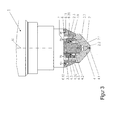
- FIG. 3 For example, a plasma cutting torch 1 is shown in which a nozzle 4 is cooled indirectly via a nozzle holder 6, to which the coolant is led away again through a coolant chamber 6.10 (WV1) and via a coolant chamber 6.11 (WR1).
- WV1 coolant chamber 6.10
- WR1 coolant chamber 6.11
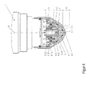
- the Indian FIG. 4 shown plasma cutting torch 1 differs from that in the FIG. 1 shown plasma cutting torch in that the nozzle 4 is cooled directly with a coolant.
- the nozzle 4 is fixed by a nozzle cap 5.
- An internal thread 5.20 of the nozzle cap 5 is screwed to an external thread 6.21 of a nozzle holder 6.
- the outer surface of the nozzle 4 and a part of the nozzle holder 6 and the inner surface of the nozzle cap 5 form a coolant space 4.10, through which the coolant flowing through coolant chambers 6.10 and 6.11 of the nozzle holder 6 (WV1) and back (WR1).
- an insulating member formed as a plasma gas guide member 3 is disposed between the nozzle 4 and an electrode 2. This achieves the same benefits as those associated with FIG. 1 are explained.
- the heat is transferred between the electrode 2 and the nozzle 4 from the warmer to the colder component through the heat well-conductive formed as a plasma gas guide part 3 insulating part.
- the plasma gas guide member 3 is in contact with the electrode 2 and the nozzle 4 by contact. Thus, caused by high temperature differences mechanical stresses in the plasma cutting torch 1 can be reduced.
- the nozzle cap 5 is also formed by the coolant flowing through the coolant space 4.10, which is formed by the outer surface of the nozzle 4 and the inner surface of the nozzle cap 5, cooled.
- the heating of the nozzle cap 5 is mainly due to the radiation of the arc or the plasma jet and the heated workpiece.
- the coolant used here is preferably a liquid, in the simplest case water.
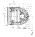
- FIG. 5 shows a plasma cutting torch 1, the plasma cutting torch of FIG. 1 similar, in which, however, in addition to the nozzle 4, a nozzle cap 8 is arranged. Holes 4.1 of the nozzle 4 and 8.1 of the nozzle cap 8 lie on a center line M. The inner surfaces of the nozzle cap 8 and a nozzle cap holder 9 form with the outer surfaces of the nozzle 4 and the nozzle holder 6 spaces 8.10 and 9.10 through which a secondary gas SG flows. This secondary gas exits the bore of the nozzle cap 8.1 and envelops the plasma jet (not shown) and provides a defined atmosphere around it. In addition, the secondary gas SG protects the nozzle 4 and the nozzle guard 8 from arcs that may form between them and the workpiece.
- the nozzle protection cap 8 must be cooled in addition to the electrode 2 and 4 nozzle.
- the heating of the nozzle cap 8 is effected in particular by the radiation of the arc or the plasma jet and the heated workpiece.
- the nozzle protection cap 8 is thermally heavily loaded and heated by highly hot glowing material and must be cooled. Therefore, heat and highly electrically conductive materials, usually metals, such as silver, copper, aluminum, tin, zinc, iron, alloyed steel or a metallic alloy (eg brass), in which these metals individually or at least 50% in total are used.
- the secondary gas SG first flows through the plasma cutting torch 1 before passing through a first space 9,10 formed by the inner surfaces of the nozzle guard holder 9 and the nozzle guard 8 and the outer surfaces of the nozzle holder 6 and the nozzle 4.
- the first space 9:10 is also bounded by an insulating part formed as a secondary gas guiding part 7, which is located between the nozzle 4 and the nozzle protecting cap 8.
- the secondary gas guide part 7 may be formed in several parts.
- the secondary gas guide part 7 In the secondary gas guide part 7 are holes 7.1. But it may also be openings, grooves or recesses through which the secondary gas SG flows.
- the secondary gas By a corresponding arrangement of the bores 7.1, for example arranged radially with a radial offset and / or an inclination to the center line M, the secondary gas can be set in rotation. This serves to stabilize the arc or the plasma jet.
- the secondary gas After passing through the secondary gas guide member 7, the secondary gas flows into an inner space 8.10, which is formed by the inner surface of the nozzle cap 8 and the outer surface of the nozzle 4, and then emerges from the bore 8.1 of the nozzle cap 8.
- the secondary gas strikes it and can influence it.
- the nozzle cap 8 is usually cooled only by the secondary gas SG.
- the gas cooling has the disadvantage that it is not effective and the required gas flow rate is very high in order to achieve acceptable cooling or heat dissipation.
- Gas volume flows of 5,000 to 11,000 l / h are often necessary here.
- the volume flow of the secondary gas must be selected so that the best cutting results are achieved. Too large volume flows, which are necessary for the cooling but often worsen the cutting result.
- Fig. 6 shows the structure of a plasma cutting torch 1 as in Fig. 4 in which, however, a nozzle protection cap 8 is additionally arranged outside the nozzle cap 5.
- Holes 4.1 of the nozzle 4 and 8.1 of the nozzle cap 8 lie on a center line M.
- the inner surfaces of the nozzle cap 8 and the nozzle protection cap holder 9 form with the outer surfaces of the nozzle cap 5 and the nozzle 4 spaces 8.10 and 9.10, through which a secondary gas SG can flow.
- the secondary gas exits from the bore 8.1 of the nozzle cap 8, surrounds the plasma jet (not shown) and provides for a defined atmosphere around selbigen.
- the secondary gas SG protects the nozzle 4, nozzle cap 5 and the nozzle cap 8 from arcs that may form between them and a workpiece (not shown). These are referred to as double arcs and can damage the nozzle 4, the nozzle cap 5 and the nozzle cap 8 lead.
- the nozzle 4, the nozzle cap 5 and the nozzle cap 8 are heavily loaded by hot high-spraying material.
- the secondary gas SG whose volume flow during piercing can be increased in relation to the value during cutting, keeps the highly spraying material away from the nozzle 4, the nozzle cap 5 and the nozzle protection cap 8, thus protecting against damage.
- the heating of the nozzle cap 8 is effected in particular by the radiation of the arc or the plasma jet and the heated workpiece. Especially when piercing the workpiece, the nozzle protection cap 8 is thermally heavily loaded and heated by highly hot glowing material and must be cooled. Therefore, for good heat and good electrical conductivity materials, usually metals, for example copper, aluminum, tin, zinc, iron or alloys, in which at least one of these metals is included, used.
- the secondary gas SG first flows through the plasma torch 1 before passing through a space 9.10 formed by the inner surfaces of the nozzle guard holder 9 and the nozzle guard 8 and the outer surfaces of a nozzle holder 6 and the nozzle cap 5.
- the space 9.10 is also bounded by an insulating part formed as a secondary gas guiding part 7 for the secondary gas SG, which is located between the nozzle cap 5 and the nozzle protecting cap 8.
- the secondary gas guide part 7 In the secondary gas guide part 7 are holes 7.1. But it may also be openings, grooves or recesses through which the secondary gas SG flows. By a corresponding arrangement of these, for example, a radial offset having and / or radially inclined with an inclination to the center line M holes 7.1, the secondary gas SG can be set in rotation. This serves to stabilize the arc or the plasma jet.
- the secondary gas SG After passing through the secondary gas guide member 7, the secondary gas SG flows into the space (inner space) 8.10 formed by the inner surface of the nozzle guard 8 and the outer surface of the nozzle cap 5 and the nozzle 4, and then exits from the bore 8.1 of the nozzle guard 8.
- the secondary gas SG strikes it and can influence it.
- the nozzle cap 8 is usually cooled only by the secondary gas SG.
- the gas cooling has the disadvantage that it is not effective and the required gas flow rate is very high in order to achieve acceptable cooling or heat dissipation.
- Gas volume flows of 5,000 to 11,000 l / h are often necessary here.
- the volume flow of the secondary gas must be selected so that the best cutting results are achieved. Too large volume flows, which are necessary for the cooling but often worsen the cutting result.
- the high gas consumption caused by large volume flows is uneconomical. This is especially true when gases other than air, such as argon, nitrogen, hydrogen, oxygen or helium are used.
- the electrical insulation between the nozzle cap 8 and the nozzle cap 5 and thus the nozzle 4 is achieved.
- the electrical insulation in combination with the secondary gas SG protects the nozzle 4, the nozzle cap 5 and the nozzle cap 8 from arcs that may form between them and a workpiece (not shown). These are called double-sided bends and may damage the nozzle, nozzle cap, and nozzle cap.
- Fig. 7 shows a plasma cutting torch 1, for which the embodiment according to the Fig. 6 statements made.
- the Düsenschutzkappenhalterung 9 is screwed with its internal thread 9.20 on the external thread 11.20 of the receptacle 11, which is designed as an insulating part.
- the receptacle 11 consists of an electrically non-conductive and heat-conducting material.
- the receptacle 11 has coolant passages 11.10 and 11.11 for the coolant forward (WV1) and coolant return return (WR1), which are designed here as bores. Through this, the coolant flows and thus cools the receptacle 11. Thus, the cooling of the nozzle protection cap holder 9 is further improved.
- the heat is transferred from the nozzle protection cap 8 via its contact surface 8.3 designed as a circular ring surface onto a contact surface 9.1 likewise designed as an annular surface on the nozzle protection cap holder 9.
- the contact surfaces 8.3 and 9.1 touch in this example non-positively, wherein the nozzle cap 8 is screwed by means of nozzle protection cap holder 9 with the internal thread 9.20 on the external thread 11.20 of the receptacle 11.
- the receptacle 11 is made of ceramic.
- Particularly suitable aluminum nitride which has a very good thermal conductivity (about 180 W / (m * K)) and a high electrical resistivity (about 10 12 ⁇ * cm).
- Coolant is simultaneously guided through coolant chambers 6.10 and 6.11 of the nozzle holder 6 to the nozzle 4 and nozzle cap 5 and cools them.
- Fig. 8 shows an embodiment of a plasma torch 1, that of the Fig. 7 similar.
- the recording 11 designed as a nozzle cover holder 9 insulating part.
- the receptacle 11 consists in this example of two parts, wherein an outer part 11.1 of an electrically non-conductive and highly heat-conductive material and an inner part 11.2 consists of a good electrical conductivity and heat well conductive material.
- the Düsenschutzkappenhalterung 9 is screwed with its internal thread 9.20 on the external thread 11.20 of the part 11.1 of the receptacle 11.
- the electrically non-conductive and heat-conductive material is made of ceramic, for example aluminum nitride, which has a very good thermal conductivity (about 180 W / (m * K)) and a high electrical resistivity about 10 12 ⁇ * cm.
- the highly electrically conductive and highly conductive material is here a metal, for example copper, aluminum, tin, zinc, alloy steel or alloys (for example, brass), in which at least one of these metals is included.
- the electrically highly conductive and highly heat-conducting material has a thermal conductivity of at least 40 W / (m * K) ⁇ and a specific electrical resistance of at most 0.01 ⁇ * cm.
- the electrically highly conductive and heat-conductive material has a thermal conductivity of at least 60 W / (m * K), better at least 90 W / (m * K) and preferably 120 W / (m * K) , More preferably, the good electrical conductivity and high thermal conductivity material has a thermal conductivity of at least 150 W / (m * K), more preferably at least 200 W / (m * K), and preferably at least 300 W / (m * K).
- the material which conducts electricity well and conducts heat well a metal such as, for example, silver, copper, aluminum, tin, zinc, iron, alloyed steel or a metallic alloy (eg brass) in which these metals are contained individually or in total at least 50%.
- a metal such as, for example, silver, copper, aluminum, tin, zinc, iron, alloyed steel or a metallic alloy (eg brass) in which these metals are contained individually or in total at least 50%.
- the use of two different materials has the advantage that for the more complex part, in which different shapes are needed, for example, different holes, recesses, grooves, openings, etc., the material can be used, which can be processed easier and cheaper. In this embodiment, this is a metal that can be machined more easily than ceramics. Both parts (11.1 and 11.2) are frictionally connected to each other by touching each other touching, whereby a good heat transfer between the cylindrical contact surfaces 11.5 and 11.6 of the two parts 11.1 and 11.2 is achieved.
- the part 11.2 of the receptacle 11 has coolant passages 11.10 and 11.11 for the coolant supply (WV1) and coolant return (WR1), which are designed here as bores. Through this, the coolant flows and cools.
- the present invention also relates to an insulating part for a plasma torch, in particular a plasma cutting torch, for electrical insulation between at least two electrically conductive components of the plasma torch, wherein it consists of at least two parts, wherein one of the parts of an electrically non-conductive and heat well conductive material and the other or another of the parts of a good electrical conductivity and heat well conductive material.
- FIG. 9 shows a further embodiment of a plasma cutting torch 1 according to the present invention, which in principle in the FIG. 8 similar embodiment shown. This also applies to those for the embodiments according to the FIGS. 6 . 7 and 8th made statements.
- the insulating member 11 designed as a receptacle 11 for the nozzle protection cap holder 9.
- the receptacle 11 consists of two parts, in which case the outer part 11.1 in contrast to in FIG. 8 shown Embodiment of a highly electrically conductive and highly heat-conductive material (for example, metal) and the inner part 11.2 of an electrically non-conductive and heat-conductive material (for example, ceramic) consists.
- the Düsenschutzkappenhalterung 9 with its internal thread 9.20 is screwed to the external thread 11.20 of the part 11.1 of the receptacle 11.
- the advantage is that the external thread can be introduced into the metallic material used for the part 11.1 and not the more difficult to process ceramic.
- FIGS. 10 to 13 show (further) different embodiments of an insulating part designed as a plasma gas guide part 3 for the plasma gas PG, which in a plasma torch 1, as shown in the FIGS. 1 to 9 is shown, can be used, wherein the respective figure with the letter “a” shows a longitudinal section and the respective figure with the letter “b” shows a partially sectioned side view.
- plasma gas guide part 3 is made of an electrically non-conductive and heat well conductive material, here for example made of ceramic.
- Particularly suitable aluminum nitride which has a very good thermal conductivity (about 180 W / (m * K)) and a high electrical resistivity (about 10 12 ⁇ * cm).
- the plasma gas guide part 3 there are radially arranged bores 3.1, which can be radially offset and / or radially inclined to the center line M, for example, and allow a plasma gas PG to rotate in the plasma cutting torch.
- the plasma gas guide member 3 in the Plasma cutting torch 1 is its contact surface 3.6 (here, for example, cylindrical outer surface) with the contact surface 4.3 (here, for example, cylindrical inner surface) of the nozzle 4, their contact surface 3.5 (here, for example, cylindrical inner surface) with the contact surface 2.3 (here cylindrical, for example Outside surface) of the electrode 2 and its contact surface 3.7 (here, for example, annular surface) with the contact surface 4.5 (here, for example, annular surface) of the nozzle 4 by contact in contact ( FIGS. 1 to 9 ).
- the contact surface 3.6 are grooves 3.8. These direct the plasma gas PG to the holes 3.1 before it is passed through them into an interior 4.2 of the nozzle 4, in which the electrode 2 is arranged.
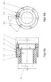
- FIGS. 11a and 11b show a plasma gas guide part 3, which consists of two parts.
- a first part 3.2 consists of an electrically non-conductive and highly heat-conductive material, while a second part 3.3 consists of a good electrical conductivity and heat well conductive material.
- ceramic again as an example aluminum nitride, which has a very good thermal conductivity (about 180 W / (m * K)) and a high electrical resistivity (10 12 ⁇ * cm) is used here for the part 3.2 of the plasma gas-conducting part 3 .
- a metal such as silver, copper, aluminum, tin, zinc, iron, alloy steel or a metallic alloy (eg brass), in which these metals individually or in total at least 50% are used.
- the thermal conductivity of the plasma gas-conducting part 3 becomes greater than if it consisted only of electrically non-conductive and heat-conducting material, such as, for example, aluminum nitride.
- electrically non-conductive and heat-conducting material such as, for example, aluminum nitride.
- copper has a higher thermal conductivity (up to about 390 W / (m * K)) than aluminum nitride (about 180 W / (m * K)), which is currently considered one of the best heat sources conductive and at the same time not electrically well conductive material applies.
- the parts 3.2 and 3.3 are connected by pushing over the contact surfaces 3.21 and 3.31.
- the parts 3.2 and 3.3 can also be non-positively connected by the juxtaposed, facing and touching contact surfaces 3.20 with 3.30, 3.21 with 3.31 and 3.22 to 3.32.
- the contact surfaces 3.20, 3.21 and 3.22 are contact surfaces of the part 3.2 and the contact surfaces 3.30, 3.31 and 3.32 are contact surfaces of the part 3.3.
- the cylindrically shaped contact surfaces 3.31 (cylindrical outer surface of the part 3.3) and 3.21 (cylindrical inner surface of the part 3.2) form a non-positive connection by intermeshing.
- an interference fit DIN EN ISO 286 for example H7 / n6, H7 / m6) is used between the cylindrical inner and outer surfaces.
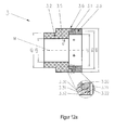
- FIGS. 12a and 12b show a plasma gas guide part 3, which consists of two parts, wherein a first part 3.2 made of an electrically non-conductive and heat-conductive material, while a second part 3.3 consists of an electrically non-conductive and non-heat conducting material.
- ceramic is used as an example, again as an example aluminum nitride, which has a very good thermal conductivity (about 180 W / (m * K)) and a high electrical resistivity (about 10 12 ⁇ * cm) , used.
- a plastic for example PEEK, PTFE (polytetrafluoroethene), torlon, polyamide-imide (PAI), polyimide (PI), which has a high temperature resistance (at least 200 ° C.) and a high specific electrical resistance can be used for the part 3.3 of the plasma gas-conducting part 3 (at least 10 6 , better at least 10 10 ⁇ * cm) can be used.
- the parts 3.2 and 3.3 are connected by pushing together the contact surfaces 3.21 and 3.31. They can also be frictionally connected by 3.30, 3.21 to 3.31 and 3.22 to 3.32 through the pressed, opposite and touching contact surfaces 3.20.
- the cylindrically shaped contact surfaces 3.31 (cylindrical outer surface of the part 3.3) and 3.21 (cylindrical inner surface of the part 3.2) then form the frictional connection by intermeshing.
- an interference fit DIN EN ISO 286 for example H7 / n6, H7 / m6 is used between the cylindrical inner and outer surfaces. It is also possible to connect both parts (3.2 and 3.3) by positive engagement and / or by gluing together.
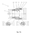
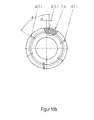
- FIGS. 13a and 13b show a plasma gas guide member 3 as shown in FIG. 12 except that another part 3.4 made of a material having the same characteristics as part 3.3 belongs to the plasma gas guide part 3.
- the parts 3.2 and 3.4 can be connected to each other as well as the parts 3.2 and 3.3, wherein the contact surfaces 3.23 are connected to 3.43, 3.24 to 3.44 and 3.25 to 3.25.
- the mechanical processing of the ceramic material is usually more difficult than that of a plastic, the processing costs are reduced and are also a variety of shapes, such as recesses, holes, etc. easier to produce when they are introduced into the plastic.
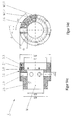
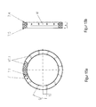
- FIGS. 14a to 14b show a further embodiment of a plasma gas guide part 3.
- Die Figures 14c and 14d show a part 3.3 of the plasma gas guide part 3.
- the show FIGS. 14a and 14c a longitudinal section and the Figures 14b and 14d a partially sectioned side view.
- a part 3.2 consists of an electrically non-conductive and highly heat-conductive material, while a part 3.3 consists of an electrically non-conductive and non-heat conducting material.
- part 3.3 of the plasma gas guide part 3 are radially arranged openings, here bores 3.1, which may be radially offset and / or radially inclined to the center line M and through which a plasma gas PG flows when the plasma gas guide member 3 is installed in the plasma cutting torch 1 (see FIGS. 1 to 9 ).
- the part 3.3 has more radially arranged holes 3.9, which are larger than the holes 3.1.
- contact surfaces are 3.61 (outer surfaces) of the parts 3.2 (round pins) with a contact surface 4.3 (here a cylindrical inner surface) of the nozzle 4 and contact surfaces 3.51 (inner surface) of the parts 3.2 (round pins) with the contact surface 2.3 (here a cylindrical outer surface) the electrode 2 by contact in contact.
- the parts 3.2 have a diameter d3 and a length 13 which is at least as large as half the difference between the diameters d10 and d20 of the part 3.3. It is even better if the length 13 is slightly larger in order to obtain a secure contact between the contact surfaces of the round pins 3.2 and the nozzle 4 and the electrode 2. It is also advantageous if the surface of the contact surfaces 3.61 and 3.51 are not flat, but the cylindrical outer surface (contact surface 2.3) of the electrode 2 and the cylindrical inner surface (contact surface 4.3) of the nozzle 4 are adapted so that a positive connection is formed.
- grooves 3.8 In the contact surface 3.6 are grooves 3.8. These direct the plasma gas PG to the holes 3.1 before it is passed through them into the interior 4.2 of the nozzle 4, in which the electrode 2 is arranged.
- the adaptation of the thermal resistance is advantageous. For example, the manufacturing costs are reduced if fewer holes are introduced and less round pins must be used.
- FIGS. 15 to 17 show (further) different embodiments of a formed as a secondary gas guide member 7 for a secondary gas SG insulating part in a plasma cutting torch 1, as in the FIGS. 6 to 9 is shown, can be used, wherein the respective figure with the letter "a” is a partially sectioned plan view and the respective figure with the letter "b” shows a sectional side view.
- FIGS. 15a and 15b show a secondary gas guide part 7 for a secondary gas SG, as in a plasma cutting torch according to the FIGS. 6 to 9 can be used.
- secondary gas guide member 7 consists of an electrically non-conductive and heat well conductive material, here, for example, ceramic.
- ceramic particularly suitable here is aluminum nitride, which has a very good thermal conductivity (about 180 W / (m * K)) and a high electrical resistivity (about 10 12 ⁇ * cm). Due to the low thermal resistance or the high thermal conductivity high temperature differences can be avoided and thereby caused mechanical stresses in the plasma cutting torch can be reduced.
- the secondary gas guide member 7 In the secondary gas guide member 7 are radially arranged holes 7.1, which can also radially or radially offset and / or radially inclined to the center line M and through which the secondary gas SG can flow or flows when the secondary gas guide member 7 is installed in the plasma cutting burner 1.
- 12 bores are offset radially by a dimension a11 and distributed equidistantly around the circumference, the angle enclosed by the centers of the bores being denoted by ⁇ 11. But it may also be openings, grooves or recesses through which the secondary gas SG flows when the secondary gas guide member 7 is installed in the plasma cutting burner 1.
- the secondary gas guide part 7 has two annular contact surfaces 7.4 and 7.5.
- the electrical insulation between the nozzle cap 8 and the nozzle cap 5 and thus the nozzle 4 of the in the FIGS. 6 to 9 achieved plasma cutting torch 1 achieved.
- the electrical insulation in combination with the secondary gas protects the nozzle 4, the nozzle cap 5 and the nozzle cap 8 from arcs that may form between them and the workpiece (not shown). These are referred to as double arcs and can damage the nozzle 4, the nozzle cap 5 and the nozzle cap 8 lead.
- FIGS. 16a and 16b also show a secondary gas guide part 7 for a secondary gas SG, which consists of two parts.
- a first part 7.2 consists of an electrically non-conductive and highly heat-conductive material, while a second part 7.3 consists of a good electrical conductivity and heat well conductive material.
- ceramic as an example is again aluminum nitride, which has a very good thermal conductivity (about 180 W / (m * K)) and a high electrical resistivity (about 10 12 ⁇ * cm), used.
- a metal such as silver, copper, aluminum, tin, zinc, iron, alloyed steel or a metallic alloy (eg brass), in which these metals individually or in total at least 50% are used.
- the thermal conductivity of the secondary gas guide part 7 becomes greater than if this consisted only of electrically non-conductive and heat-conducting material, such as aluminum nitride.
- electrically non-conductive and heat-conducting material such as aluminum nitride.
- copper has a higher thermal conductivity (up to about 390 W / (m * K)) than aluminum nitride (about 180 W / (m * K)), which is currently one of the best heat-conducting and non-electric ones good conductive materials applies. This leads through the better conductivity to an even better heat exchange between the nozzle cap 8 and the nozzle cap 5 of the plasma cutting burner 1 of FIGS. 6 to 9 ,
- the parts are 7.2 and 7.3 connected by pushing the contact surfaces 7.21 and 7.31.
- Parts 7.2 and 7.3 can also be frictionally connected to 7.30, 7.21 to 7.31 and 7.22 to 7.32 through the contact surfaces 7.20, which are pressed against one another and located opposite each other.
- the contact surfaces 7.20, 7.21 and 7.22 are contact surfaces of the part 7.2 and the contact surfaces 7.30, 7.31 and 7.32 are contact surfaces of the part 7.3.
- the cylindrically shaped contact surfaces 7.31 (cylindrical outer surface of the part 7.3) and 7.21 (cylindrical inner surface of the part 7.2) form by intermeshing a non-positive connection.
- an interference fit DIN EN ISO 286 (for example H7 / n6, H / m6) is used between the cylindrical inner and outer surfaces.
- twelve holes 7.1 are introduced in part 7.3 of metal, which have a radial offset a11 and distributed at an angle ⁇ 11 equidistant on the circumference of the gas guide.
- shapes such as grooves, recesses, holes, etc. easier to produce when they are introduced into the metal.
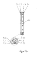
- FIGS. 17a and 17b also show a secondary gas guide part 7 for a secondary gas SG, which consists of two parts.
- a first part 7.2 consists of a good electrical conductivity and good thermal conductivity material and a second part 7.3 of an electrically non-conductive and heat-conductive material.
- a secondary gas guide member 7 for a secondary gas SG which in a plasma cutting torch according to the Fig. 6 to 9 can be used shown.
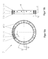
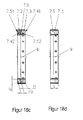
- Fig. 18a shows a plan view and the Fig. 18b and 18c cut side views of different embodiments thereof.
- Fig. 18d shows a non-electrically conductive and heat non-conductive material existing part 7.3 of the secondary gas guide part 7th
- part 7.3 of the secondary gas guide part 7 are radially arranged holes 7.1, which can also be offset radially or radially and / or radially inclined to the center line M and through which the secondary gas SG can flow when the secondary gas guide member 7 is installed in the plasma cutting burner 1.
- twelve bores are offset radially by a dimension a11 and distributed equidistantly around the circumference, the angle enclosed by the centers of the bores being designated ⁇ 11 (here for example 30 °). But it may also be openings, grooves or recesses through which the secondary gas SG flows when the secondary gas guide member 7 in the plasma cutting torch 1 (see, for example Fig. 6 to 9 ) is installed.
- Fig. 18d shows that in this example, the part 7.3 has twelve more axially arranged holes 7.9, which are larger than the holes or openings 7.1.
- Figs. 18a and 18b are in these holes 7.9 twelve parts 7.2, which are exemplified here as round pins introduced.
- the round pins 7.2 consist of an electrically non-conductive and heat well conductive material, while the part 7.3 consists of an electrically non-conductive and heat non-conductive material.
- the parts 7.2 have a diameter d7 and a length 17 which is at least as large as the width b of the part 7.3. It is even better if the length 17 is slightly larger in order to obtain a secure contact between the contact surfaces of the round pins 7.2 and the nozzle cap 5 and the nozzle cap 8.
- the Fig. 18c shows another embodiment of the secondary gas guide member 7 for secondary gas.
- the part 7.3 consists of an electrically non-conductive and heat non-conductive material
- the round pins 7.2 consist of an electrically non-conductive and heat well conductive material
- the round pins 7.6 consist of a good electrical conductivity and heat well conductive material.
- the parts 7.2 have a diameter d7 and a length 171.
- the parts 7.6 have in this example the same diameter and a length 172, wherein the sum of the lengths 171 and 172 is at least as large as the width b of the part 7.3. It is even better if the sum of the lengths is slightly larger, for example greater than 0.1 mm to obtain a secure contact between the contact surfaces 7.51 of the round pins 7.2 and the nozzle cap 5 and the contact surfaces 7.41 of the round pins 7.6 and the nozzle cap 8.
- the present invention thus also relates in generalized form to an insulating part for a plasma torch, in particular a plasma cutting torch, for electrical insulation between at least two electrically conductive components of the plasma torch, the insulating part consisting of at least three parts, one of the parts made of an electrically non-conductive and heat-conductive material, another of the parts of an electrically non-conductive and non-heat conductive material and the other or another of the parts consists of a good electrical conductivity and heat well conductive material.
- the in the 15 to 18 shown secondary gas guide parts 7 can also in a plasma cutting torch 1 according to Fig. 5 be used. There, the electrical insulation between the nozzle cap 8 and the nozzle 4 is realized by the use of this secondary gas guide part 7.
- the electrical insulation in combination with the secondary gas SG protects the nozzle 4 and the nozzle protection cap 8 from arcs that can form between them and a workpiece. These are referred to as double arcs and can lead to damage of the nozzle 4 and the nozzle cap 8.
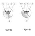
- Fig. 19a to 19d show sectional views of arrangements of a nozzle 4 and a secondary gas guide member 7 for a secondary gas SG according to particular embodiments of the invention in the 15 to 18 ,
- Fig. 5 and to the 15 to 18 are the comments on Fig. 5 and to the 15 to 18 .
- Fig. 19a an arrangement with a secondary gas guide part 7 according to Figs. 15a and 15b .
- Fig. 19b an arrangement with a secondary gas guide part according to the Fig. 16a and 16b .
- Fig. 19c an arrangement with a secondary gas guide part according to the Fig. 17a and 17b and Fig. 19d an arrangement with a secondary gas guide part according to Fig. 18a and Fig. 18b ,
- the secondary gas guide member 7 may be connected to the nozzle 4 in the simplest case by superimposing. But they can also be positively and non-positively connected or by gluing. When using metal / metal and / or metal / ceramic at the junction and soldering is possible as a connection.
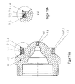
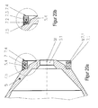
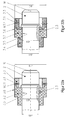
- Fig. 20a to 20d show sectional views of arrangements of a nozzle cap 5 and a secondary gas guide member 7 for a secondary gas SG according to the 15 to 18 according to particular embodiments of the invention.
- Fig. 6 to 9 and to the 15 to 18 are the comments on the Fig. 6 to 9 and to the 15 to 18 .
- Fig. 20a an arrangement with a secondary gas guide part according to the Figs. 15a and 15b ;
- Fig. 20b an arrangement with a secondary gas guide part according to the Fig. 16a and 16b ;
- Fig. 20c an arrangement with a secondary gas guide part according to Fig. 17a and 17b and
- Fig. 20d an arrangement with a secondary gas guide part according to the Fig. 18a to 18d ,
- the secondary gas guide member 7 may be connected to the nozzle cap 5 in the simplest case by superimposing. But they can also be positively and non-positively connected or gluing. When using metal / metal and / or metal / ceramic at the junction and soldering is possible as a connection.
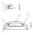
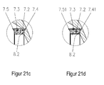
- Fig. 21a to 21d show sectional views of arrangements of a nozzle cap 8 and a secondary gas guide member 7 for a secondary gas SG according to the 15 to 18 ,
- Fig. 5 to 9 and to the 15 to 18 are the comments on the Fig. 5 to 9 and to the 15 to 18 .
- Fig. 21a an arrangement with a secondary gas guide part according to the Figs. 15a and 15b
- Fig. 21b an arrangement with a secondary gas guide part according to the Fig. 16a and 16b
- Fig. 21c an arrangement with a secondary gas guide part according to the Fig. 17a and 17b
- Fig. 21d an arrangement with a secondary gas guide part according to the Fig. 18a to 18d
- the secondary gas guide member 7 may be connected to the nozzle protection cap 8 in the simplest case by superimposing. she but can also be positively and non-positively connected or gluing. When using metal / metal and / or metal / ceramic at the junction and soldering is possible as a connection.
- Figs. 22a and 22b show arrangements of an electrode 2 and a plasma gas guide part 3 for a plasma gas PG according to the Fig. 11 to 13 according to particular embodiments of the invention.
- FIG. 22a an arrangement with a plasma gas guide part according to Fig. 11a and Fig. 11b as well as the Fig. 22b an arrangement with a plasma gas guide part according to Fig. 13a and Fig. 13b ,
- a contact surface 2.3 for example, a cylindrical outer surface of the electrode 2 and a contact surface 3.5 a cylindrical inner surface of the plasma gas guide part 3.
- a clearance with little play for example H7 / h6 according to DIN EN ISO 286 between the cylindrical inner and Used on the one hand to nesting and on the other hand a good contact and thus low thermal resistance and thus good heat transfer.
- the heat transfer can be improved by applying thermal paste to these contact surfaces. Then a fit with a larger game, for example H7 / g6 can be used.
- the Fig. 23 shows an arrangement of an electrode 2 and a plasma gas guide part 3 for a plasma gas PG according to a particular embodiment of the present invention.
- contact surfaces are 3.51 of the round pins 3.2 of the plasma gas guide part 3 with a contact surface 2.3 (here, for example, cylindrical outer surface) of the electrode 2 by contact in contact (see also Fig. 1 to 9 ).
- the parts 3.2 have a diameter d3 and a length 13 which is at least equal to half the difference between the diameters d10 and d20 of the part 3.3. It is even better if the length 13 is slightly larger in order to obtain a secure contact between the contact surfaces of the round pins 3.2 and the nozzle 4 and the electrode 2. It is advantageous, furthermore, if the surface of the contact surfaces 3.61 and 3.51 not just, but the cylindrical outer surface (contact surface 2.3) of the electrode 2 and the cylindrical inner surface (contact surface 4.3) of the nozzle are adapted so that a positive connection is formed.
- wearing parts and the insulating part or the gas guide part are enumerated by way of example only. Of course, other combinations, such as nozzle and gas guide part possible.
- cooling liquid or the like When reference has been made in the foregoing description to cooling liquid or the like, it is intended to mean a cooling medium in general terms.
- Electrode good conducting should mean that the specific electrical resistance is not more than 0.01 ⁇ * cm.
- Electrode non-conductive shall mean that the specific resistance is at least 10 6 ⁇ * cm, better at least 10 10 ⁇ * cm and / or that the voltage breakdown strength is at least 7 kV / mm, better at least 10 kV / mm.
- Heat well conductive should mean that the thermal conductivity is at least 40 W / (m * K), better at least 60 W / (m * K), even better at least 90 W / (m * K).
- Heat well conductive should mean that the thermal conductivity is at least 120 W / (m * K), better at least 150 W / (m * K), even better at least 180 W / (m * K).
- thermal conductivity is at least 200 W / (m * K), better at least 300 W / (m * K).
Landscapes
- Physics & Mathematics (AREA)
- Engineering & Computer Science (AREA)
- Plasma & Fusion (AREA)
- Spectroscopy & Molecular Physics (AREA)
- Plasma Technology (AREA)
- Arc Welding In General (AREA)
Priority Applications (11)
| Application Number | Priority Date | Filing Date | Title |
|---|---|---|---|
| PCT/IB2014/001275 WO2014184656A2 (fr) | 2013-05-16 | 2014-07-04 | Pièce isolante en une ou plusieurs parties pour un chalumeau à plasma, en particulier un chalumeau de coupe à plasma, ainsi que dispositifs et chalumeaux à plasma pourvus de celle-ci |
| JP2016513457A JP6643979B2 (ja) | 2013-10-04 | 2014-07-04 | プラズマ切断トーチ用の複数部分からなる絶縁部分、ならびにそれを有するアセンブリおよびプラズマ切断トーチ |
| RU2015153934A RU2691729C2 (ru) | 2013-05-16 | 2014-07-04 | Монолитная или составная изолирующая деталь для плазменной горелки, в частности горелки для плазменной резки, а также устройство и плазменная горелка с этим устройством |
| MX2015015427A MX370068B (es) | 2013-05-16 | 2014-07-04 | Componente aislante de una o varias partes para un soplete de plasma, en particular un soplete cortador de plasma, y montajes y sopletes de plasma que lo comprenden. |
| BR112015028734-4A BR112015028734B1 (pt) | 2013-10-04 | 2014-07-04 | Peça isolante de uma ou mais partes para uma tocha de arco por plasma, em particular, uma tocha de corte por plasma e disposições e tochas de plasma tendo a mesma |
| CA2910221A CA2910221C (fr) | 2013-05-16 | 2014-07-04 | Piece isolante en une ou plusieurs parties pour un chalumeau a plasma, en particulier un chalumeau de coupe a plasma, ainsi que dispositifs et chalumeaux a plasma pourvus de celle-ci |
| US14/890,615 US10485086B2 (en) | 2013-05-16 | 2014-07-04 | Single or multi-part insulating component for a plasma torch, particularly a plasma cutting torch, and assemblies and plasma torches having the same |
| CN201480027298.3A CN105230131B (zh) | 2013-05-16 | 2014-07-04 | 用于等离子体炬且尤其是等离子体割炬的单件或多件式绝缘构件及具有该绝缘构件的组件和等离子体炬 |
| KR1020157035646A KR102054543B1 (ko) | 2013-05-16 | 2014-07-04 | 플라즈마 토치, 특히 플라즈마 절단 토치의 단일 또는 다수-부분의 절연 부품, 및 이를 가지는 플라즈마 토치와 조립체 |
| ZA2015/08161A ZA201508161B (en) | 2013-05-16 | 2015-11-04 | Single or multi-part insulating component for a plasma torch, particularly a plasma cutting torch, and assemblies and plasma torches having the same |
| US16/550,845 US20200015345A1 (en) | 2013-05-16 | 2019-08-26 | Single or multi-part insulating component for a plasma torch, particularly a plasma cutting torch, and assemblies and plasma torches having the same |
Applications Claiming Priority (1)
| Application Number | Priority Date | Filing Date | Title |
|---|---|---|---|
| DE102013008353 | 2013-05-16 |
Publications (3)
| Publication Number | Publication Date |
|---|---|
| EP2804450A2 true EP2804450A2 (fr) | 2014-11-19 |
| EP2804450A3 EP2804450A3 (fr) | 2014-12-17 |
| EP2804450B1 EP2804450B1 (fr) | 2022-05-04 |
Family
ID=49303695
Family Applications (1)
| Application Number | Title | Priority Date | Filing Date |
|---|---|---|---|
| EP13004796.2A Active EP2804450B1 (fr) | 2013-05-16 | 2013-10-04 | Pièce isolante en plusieurs parties pour une torche à arc plasma, torche et agencements associés dotés de celle-ci et procédé associé |
Country Status (11)
| Country | Link |
|---|---|
| US (2) | US10485086B2 (fr) |
| EP (1) | EP2804450B1 (fr) |
| KR (1) | KR102054543B1 (fr) |
| CN (1) | CN105230131B (fr) |
| CA (1) | CA2910221C (fr) |
| ES (1) | ES2923761T3 (fr) |
| MX (1) | MX370068B (fr) |
| PL (1) | PL2804450T3 (fr) |
| RU (1) | RU2691729C2 (fr) |
| WO (1) | WO2014184656A2 (fr) |
| ZA (1) | ZA201508161B (fr) |
Families Citing this family (14)
| Publication number | Priority date | Publication date | Assignee | Title |
|---|---|---|---|---|
| EP2942144B1 (fr) * | 2014-05-07 | 2024-07-03 | Kjellberg-Stiftung | Système de brûleur pour découpage au jet plasma et utilisation de pièces d'usure pour un système de brûleur pour découpage au jet de plasma |
| JP6522967B2 (ja) | 2015-01-30 | 2019-05-29 | 株式会社小松製作所 | プラズマトーチ用センタパイプ、接触子、電極、及びプラズマトーチ |
| JP6522968B2 (ja) * | 2015-01-30 | 2019-05-29 | 株式会社小松製作所 | プラズマトーチ用絶縁ガイド、及び交換部品ユニット |
| JP6636249B2 (ja) * | 2015-01-30 | 2020-01-29 | 株式会社小松製作所 | プラズマトーチ用交換部品ユニット |
| DE102016219350A1 (de) * | 2016-10-06 | 2018-04-12 | Kjellberg-Stiftung | Düsenschutzkappe, Lichtbogenplasmabrenner mit dieser Düsenschutzkappe sowie eine Verwendung des Lichtbogenplasmabrenners |
| KR102646623B1 (ko) * | 2017-01-23 | 2024-03-11 | 에드워드 코리아 주식회사 | 플라즈마 발생 장치 및 가스 처리 장치 |
| KR102686242B1 (ko) | 2017-01-23 | 2024-07-17 | 에드워드 코리아 주식회사 | 질소 산화물 감소 장치 및 가스 처리 장치 |
| CA3032753C (fr) * | 2017-06-15 | 2021-07-20 | Viktor Khrist'yanovich MANN | Methode et dispositif de bris de croute electrolytique par coupe de separation au plasma |
| RU2020129100A (ru) * | 2018-02-20 | 2022-03-21 | ЭРЛИКОН МЕТКО (ЮЭс) ИНК. | Однодуговой каскадный плазмотрон низкого давления, использующий пакет нейтродов как способ контроля плазменной дуги |
| KR102796422B1 (ko) * | 2019-09-12 | 2025-04-16 | 크엘베르크-스티프텅 | 아크 토치 및 플라즈마 토치용 마모 부품, 이를 포함하는 아크 토치 및 플라즈마 토치, 아크 토치와 플라즈마 토치용 전극 제조방법 및 플라즈마 절단 방법 (wear part for an arc torch and plasma torch, arc torch and plasma torch comprising same, method for plasma cutting and method for producing an electrode for an arc torch and plasma torch) |
| CN110524087B (zh) * | 2019-09-26 | 2024-06-18 | 徐慕庆 | 一种割嘴及自动点火的割枪 |
| US10978225B1 (en) | 2020-03-12 | 2021-04-13 | Lawrence Livermore National Security, Llc | High-voltage insulator having multiple materials |
| DE102020125073A1 (de) * | 2020-08-05 | 2022-02-10 | Kjellberg-Stiftung | Elektrode für einen Plasmaschneidbrenner, Anordnung mit derselben, Plasmaschneidbrenner mit derselben sowie Verfahren zum Plasmaschneiden |
| KR20230068789A (ko) * | 2021-11-11 | 2023-05-18 | 삼성에스디아이 주식회사 | 레이저 용접 노즐 |
Family Cites Families (26)
| Publication number | Priority date | Publication date | Assignee | Title |
|---|---|---|---|---|
| JPS4872053A (fr) * | 1971-12-30 | 1973-09-28 | ||
| EP0094984A1 (fr) * | 1982-07-12 | 1983-11-30 | Manfred J. Wallner | Chalumeau soudeur ou coupeur à l'arc |
| US4659899A (en) * | 1984-10-24 | 1987-04-21 | The Perkin-Elmer Corporation | Vacuum-compatible air-cooled plasma device |
| JP2640707B2 (ja) * | 1991-02-28 | 1997-08-13 | 株式会社小松製作所 | 切断用プラズマトーチ |
| WO1992015421A1 (fr) * | 1991-02-28 | 1992-09-17 | Kabushiki Kaisha Komatsu Seisakusho | Chalumeau coupeur a plasma |
| JPH0639276U (ja) * | 1992-10-20 | 1994-05-24 | 株式会社小松製作所 | プラズマ切断機用トーチ |
| JP3260018B2 (ja) * | 1993-09-22 | 2002-02-25 | 小池酸素工業株式会社 | プラズマ切断トーチ |
| AT405472B (de) * | 1997-03-04 | 1999-08-25 | Bernhard Dr Platzer | Verfahren und vorrichtung zum erzeugen eines plasmas |
| US5906758A (en) * | 1997-09-30 | 1999-05-25 | The Esab Group, Inc. | Plasma arc torch |
| RU2145536C1 (ru) * | 1998-04-07 | 2000-02-20 | Акционерное общество открытого типа "Научно-исследовательский технологический институт" (АО "НИТИ-ТЕСАР") | Плазмотрон для воздушно-плазменной резки |
| FR2777214B1 (fr) * | 1998-04-09 | 2000-05-19 | Soudure Autogene Francaise | Torche et procede de coupage ou soudage a l'arc electrique |
| JP2000082774A (ja) * | 1998-06-30 | 2000-03-21 | Sumitomo Electric Ind Ltd | パワ―モジュ―ル用基板およびその基板を用いたパワ―モジュ―ル |
| JP2000052043A (ja) * | 1998-08-05 | 2000-02-22 | Koike Sanso Kogyo Co Ltd | プラズマトーチ |
| JP3625040B2 (ja) * | 1999-08-11 | 2005-03-02 | 株式会社小松製作所 | プラズマ加工機、プラズマトーチ及びその部品の着脱方法 |
| US6320156B1 (en) * | 1999-05-10 | 2001-11-20 | Komatsu Ltd. | Plasma processing device, plasma torch and method for replacing components of same |
| DE60238470D1 (de) * | 2001-02-27 | 2011-01-13 | Yantai Longyuan Power Tech Co | Plasmazünder mit zusammengesetzter kathode |
| WO2002091809A2 (fr) * | 2001-05-03 | 2002-11-14 | Apit Corp. S.A. | Procede et dispositif de generation d'un rideau de gaz active pour traitement de surface |
| CN1283131C (zh) * | 2001-10-05 | 2006-11-01 | 泰克纳等离子系统公司 | 用于固态电源的多线圈感应等离子体火炬 |
| JP3652350B2 (ja) * | 2002-12-17 | 2005-05-25 | コマツ産機株式会社 | プラズマ加工方法 |
| KR101371979B1 (ko) * | 2005-04-19 | 2014-03-07 | 하이퍼썸, 인크. | 각진 쉴드 흐름 주입을 제공하는 플라즈마 아크 토치 |
| WO2006118003A1 (fr) * | 2005-04-28 | 2006-11-09 | Hitachi Metals, Ltd. | Substrat de nitrure de silicium, son procédé de fabrication, et carte de circuit imprimé en nitrure de silicium et module semi-conducteur l'utilisant |
| US8101882B2 (en) * | 2005-09-07 | 2012-01-24 | Hypertherm, Inc. | Plasma torch electrode with improved insert configurations |
| FR2914369B1 (fr) * | 2007-03-30 | 2014-02-07 | Snecma | Allumeur electrolytique pour moteur-fusee a monergol |
| JP5413218B2 (ja) * | 2010-01-27 | 2014-02-12 | Jfeエンジニアリング株式会社 | 中空電極アーク・レーザ同軸複合溶接方法 |
| US9605376B2 (en) * | 2011-06-28 | 2017-03-28 | Mtix Ltd. | Treating materials with combined energy sources |
| AU2012371647B2 (en) * | 2012-02-28 | 2015-05-07 | Sulzer Metco (Us), Inc. | Extended cascade plasma gun |
-
2013
- 2013-10-04 PL PL13004796.2T patent/PL2804450T3/pl unknown
- 2013-10-04 ES ES13004796T patent/ES2923761T3/es active Active
- 2013-10-04 EP EP13004796.2A patent/EP2804450B1/fr active Active
-
2014
- 2014-07-04 KR KR1020157035646A patent/KR102054543B1/ko active Active
- 2014-07-04 RU RU2015153934A patent/RU2691729C2/ru active
- 2014-07-04 US US14/890,615 patent/US10485086B2/en active Active
- 2014-07-04 CA CA2910221A patent/CA2910221C/fr active Active
- 2014-07-04 MX MX2015015427A patent/MX370068B/es active IP Right Grant
- 2014-07-04 WO PCT/IB2014/001275 patent/WO2014184656A2/fr not_active Ceased
- 2014-07-04 CN CN201480027298.3A patent/CN105230131B/zh active Active
-
2015
- 2015-11-04 ZA ZA2015/08161A patent/ZA201508161B/en unknown
-
2019
- 2019-08-26 US US16/550,845 patent/US20200015345A1/en not_active Abandoned
Non-Patent Citations (1)
| Title |
|---|
| None |
Also Published As
| Publication number | Publication date |
|---|---|
| RU2015153934A (ru) | 2017-06-21 |
| WO2014184656A3 (fr) | 2015-01-22 |
| ZA201508161B (en) | 2017-05-31 |
| EP2804450B1 (fr) | 2022-05-04 |
| WO2014184656A2 (fr) | 2014-11-20 |
| CN105230131A (zh) | 2016-01-06 |
| US10485086B2 (en) | 2019-11-19 |
| CA2910221C (fr) | 2021-11-09 |
| ES2923761T3 (es) | 2022-09-30 |
| KR20160053847A (ko) | 2016-05-13 |
| US20200015345A1 (en) | 2020-01-09 |
| MX370068B (es) | 2019-11-29 |
| RU2015153934A3 (fr) | 2018-03-01 |
| CN105230131B (zh) | 2018-10-09 |
| RU2691729C2 (ru) | 2019-06-18 |
| EP2804450A3 (fr) | 2014-12-17 |
| US20160120014A1 (en) | 2016-04-28 |
| PL2804450T3 (pl) | 2022-12-19 |
| CA2910221A1 (fr) | 2014-11-20 |
| MX2015015427A (es) | 2016-08-04 |
| KR102054543B1 (ko) | 2020-01-22 |
Similar Documents
| Publication | Publication Date | Title |
|---|---|---|
| EP2804450B1 (fr) | Pièce isolante en plusieurs parties pour une torche à arc plasma, torche et agencements associés dotés de celle-ci et procédé associé | |
| DE2025368C3 (de) | Elektrischer Lichtbogenbrenner | |
| DE102009016932B4 (de) | Kühlrohre und Elektrodenaufnahme für einen Lichtbogenplasmabrenner sowie Anordnungen aus denselben und Lichtbogenplasmabrenner mit denselben | |
| EP2465334B1 (fr) | Capot de protection de buse et porte-capot de protection de buse ainsi que torche à plasma équipée de l'un et/ou de l'autre | |
| EP2210455B1 (fr) | Electrode pour torche a plasma | |
| DE102011088433A1 (de) | Verfahren und Plasmalichtbogenbrennersystem zum Markieren und Schneiden von Werkstücken mit dem selben Satz an Hilfsstoffen | |
| EP2855071B1 (fr) | Chalumeau pour le soudage au tungstène et au gaz inerte | |
| EP3684544B1 (fr) | Buse pour tête de chalumeau à plasma, tête de découpe au laser et tête de découpe au laser à plasma | |
| DE102008018530A1 (de) | Düse für einen flüssigkeitsgekühlten Plasmabrenner, Anordnung aus derselben und einer Düsenkappe sowie flüssigkeitsgekühlter Plasmabrenner mit einer derartigen Anordnung | |
| EP2849542B1 (fr) | Structure d'électrodes pour torches de coupage au plasma | |
| DE102019100581A1 (de) | Gasdüse zum Ausströmen eines Schutzgasstromes und Brennerhals mit einer Gasdüse | |
| EP2667689B1 (fr) | Électrode pour chalumeau de coupe au plasma ainsi que son utilisation | |
| EP3639631A2 (fr) | Électrodes pour torches à plasma refroidies par gaz et liquide, agencement d'une électrode et d'un tube de refroidissement, guidage des gaz, torche à plasma, procédé de guidage des gaz dans une torche à plasma et procédé pour faire fonctionner une torche à plasma | |
| EP2457681B1 (fr) | Torche pour le soudage au gaz inerte et électrode tungstène et électrode destinée à être utilisée dans une telle torche | |
| DE202016102971U1 (de) | Schweißbrennerkopf mit Kühlstromleiteinrichtung | |
| EP3829807B1 (fr) | Pièces de liaison d'une tête de traitement destinée à un traitement thermique de matériau, en particulier d'une tête de chalumeau à plasma | |
| DE102017121722B4 (de) | Brennerkörper zum thermischen Fügen, Brenner mit Brennerkörper und Fügevorrichtung | |
| EP3524038B1 (fr) | Capot de protection de buse, torche à plasma équipée de l'un ainsi qu'utilisation de la torche à plasma | |
| EP4029356A2 (fr) | Pièce d'usure pour chalumeau à arc et chalumeau à plasma et chalumeau à arc et chalumeau à plasma comprenant cette pièce d'usure et procédé de découpage au plasma et procédé de fabrication d'une électrode pour un chalumeau à arc et un chalumeau à plasma | |
| EP4193811B1 (fr) | Électrode pour un chalumeau de découpe au plasma, chalumeau de découpe au plasma et procédé de découpe au plasma avec la même | |
| WO2024068182A1 (fr) | Composant tel qu'une pièce d'usure pour une torche à arc, en particulier un brûleur à plasma ou une torche de découpe au plasma, torche à arc le comprenant, et procédé de découpe au plasma | |
| DE3136799C2 (de) | Plasmalichtbogenofen | |
| DE2033072C (de) | Lichtbogen-Plasmabrenner mit einer gekühlten Kathode und gekühlten Anode | |
| DE1003880B (de) | Schweissbrenner zum Lichtbogen-Schutzgas-Schweissen mit keramischer Gasduese |
Legal Events
| Date | Code | Title | Description |
|---|---|---|---|
| PUAL | Search report despatched |
Free format text: ORIGINAL CODE: 0009013 |
|
| PUAI | Public reference made under article 153(3) epc to a published international application that has entered the european phase |
Free format text: ORIGINAL CODE: 0009012 |
|
| 17P | Request for examination filed |
Effective date: 20131004 |
|
| AK | Designated contracting states |
Kind code of ref document: A2 Designated state(s): AL AT BE BG CH CY CZ DE DK EE ES FI FR GB GR HR HU IE IS IT LI LT LU LV MC MK MT NL NO PL PT RO RS SE SI SK SM TR |
|
| AX | Request for extension of the european patent |
Extension state: BA ME |
|
| AK | Designated contracting states |
Kind code of ref document: A3 Designated state(s): AL AT BE BG CH CY CZ DE DK EE ES FI FR GB GR HR HU IE IS IT LI LT LU LV MC MK MT NL NO PL PT RO RS SE SI SK SM TR |
|
| AX | Request for extension of the european patent |
Extension state: BA ME |
|
| RIC1 | Information provided on ipc code assigned before grant |
Ipc: H05H 1/34 20060101AFI20141110BHEP |
|
| R17P | Request for examination filed (corrected) |
Effective date: 20150616 |
|
| RAP1 | Party data changed (applicant data changed or rights of an application transferred) |
Owner name: KJELLBERG-STIFTUNG |
|
| STAA | Information on the status of an ep patent application or granted ep patent |
Free format text: STATUS: EXAMINATION IS IN PROGRESS |
|
| 17Q | First examination report despatched |
Effective date: 20200117 |
|
| GRAP | Despatch of communication of intention to grant a patent |
Free format text: ORIGINAL CODE: EPIDOSNIGR1 |
|
| STAA | Information on the status of an ep patent application or granted ep patent |
Free format text: STATUS: GRANT OF PATENT IS INTENDED |
|
| INTG | Intention to grant announced |
Effective date: 20210622 |
|
| RAP3 | Party data changed (applicant data changed or rights of an application transferred) |
Owner name: KJELLBERG-STIFTUNG |
|
| GRAJ | Information related to disapproval of communication of intention to grant by the applicant or resumption of examination proceedings by the epo deleted |
Free format text: ORIGINAL CODE: EPIDOSDIGR1 |
|
| STAA | Information on the status of an ep patent application or granted ep patent |
Free format text: STATUS: EXAMINATION IS IN PROGRESS |
|
| GRAP | Despatch of communication of intention to grant a patent |
Free format text: ORIGINAL CODE: EPIDOSNIGR1 |
|
| STAA | Information on the status of an ep patent application or granted ep patent |
Free format text: STATUS: GRANT OF PATENT IS INTENDED |
|
| INTC | Intention to grant announced (deleted) | ||
| INTG | Intention to grant announced |
Effective date: 20211119 |
|
| GRAS | Grant fee paid |
Free format text: ORIGINAL CODE: EPIDOSNIGR3 |
|
| GRAA | (expected) grant |
Free format text: ORIGINAL CODE: 0009210 |
|
| STAA | Information on the status of an ep patent application or granted ep patent |
Free format text: STATUS: THE PATENT HAS BEEN GRANTED |
|
| AK | Designated contracting states |
Kind code of ref document: B1 Designated state(s): AL AT BE BG CH CY CZ DE DK EE ES FI FR GB GR HR HU IE IS IT LI LT LU LV MC MK MT NL NO PL PT RO RS SE SI SK SM TR |
|
| REG | Reference to a national code |
Ref country code: GB Ref legal event code: FG4D Free format text: NOT ENGLISH |
|
| REG | Reference to a national code |
Ref country code: CH Ref legal event code: EP |
|
| REG | Reference to a national code |
Ref country code: AT Ref legal event code: REF Ref document number: 1490570 Country of ref document: AT Kind code of ref document: T Effective date: 20220515 |
|
| REG | Reference to a national code |
Ref country code: DE Ref legal event code: R096 Ref document number: 502013016131 Country of ref document: DE |
|
| REG | Reference to a national code |
Ref country code: IE Ref legal event code: FG4D Free format text: LANGUAGE OF EP DOCUMENT: GERMAN |
|
| REG | Reference to a national code |
Ref country code: NL Ref legal event code: FP |
|
| REG | Reference to a national code |
Ref country code: LT Ref legal event code: MG9D |
|
| REG | Reference to a national code |
Ref country code: ES Ref legal event code: FG2A Ref document number: 2923761 Country of ref document: ES Kind code of ref document: T3 Effective date: 20220930 |
|
| PG25 | Lapsed in a contracting state [announced via postgrant information from national office to epo] |
Ref country code: SE Free format text: LAPSE BECAUSE OF FAILURE TO SUBMIT A TRANSLATION OF THE DESCRIPTION OR TO PAY THE FEE WITHIN THE PRESCRIBED TIME-LIMIT Effective date: 20220504 Ref country code: PT Free format text: LAPSE BECAUSE OF FAILURE TO SUBMIT A TRANSLATION OF THE DESCRIPTION OR TO PAY THE FEE WITHIN THE PRESCRIBED TIME-LIMIT Effective date: 20220905 Ref country code: NO Free format text: LAPSE BECAUSE OF FAILURE TO SUBMIT A TRANSLATION OF THE DESCRIPTION OR TO PAY THE FEE WITHIN THE PRESCRIBED TIME-LIMIT Effective date: 20220804 Ref country code: LT Free format text: LAPSE BECAUSE OF FAILURE TO SUBMIT A TRANSLATION OF THE DESCRIPTION OR TO PAY THE FEE WITHIN THE PRESCRIBED TIME-LIMIT Effective date: 20220504 Ref country code: HR Free format text: LAPSE BECAUSE OF FAILURE TO SUBMIT A TRANSLATION OF THE DESCRIPTION OR TO PAY THE FEE WITHIN THE PRESCRIBED TIME-LIMIT Effective date: 20220504 Ref country code: GR Free format text: LAPSE BECAUSE OF FAILURE TO SUBMIT A TRANSLATION OF THE DESCRIPTION OR TO PAY THE FEE WITHIN THE PRESCRIBED TIME-LIMIT Effective date: 20220805 Ref country code: FI Free format text: LAPSE BECAUSE OF FAILURE TO SUBMIT A TRANSLATION OF THE DESCRIPTION OR TO PAY THE FEE WITHIN THE PRESCRIBED TIME-LIMIT Effective date: 20220504 Ref country code: BG Free format text: LAPSE BECAUSE OF FAILURE TO SUBMIT A TRANSLATION OF THE DESCRIPTION OR TO PAY THE FEE WITHIN THE PRESCRIBED TIME-LIMIT Effective date: 20220804 |
|
| PG25 | Lapsed in a contracting state [announced via postgrant information from national office to epo] |
Ref country code: RS Free format text: LAPSE BECAUSE OF FAILURE TO SUBMIT A TRANSLATION OF THE DESCRIPTION OR TO PAY THE FEE WITHIN THE PRESCRIBED TIME-LIMIT Effective date: 20220504 Ref country code: LV Free format text: LAPSE BECAUSE OF FAILURE TO SUBMIT A TRANSLATION OF THE DESCRIPTION OR TO PAY THE FEE WITHIN THE PRESCRIBED TIME-LIMIT Effective date: 20220504 Ref country code: IS Free format text: LAPSE BECAUSE OF FAILURE TO SUBMIT A TRANSLATION OF THE DESCRIPTION OR TO PAY THE FEE WITHIN THE PRESCRIBED TIME-LIMIT Effective date: 20220904 |
|
| PG25 | Lapsed in a contracting state [announced via postgrant information from national office to epo] |
Ref country code: SM Free format text: LAPSE BECAUSE OF FAILURE TO SUBMIT A TRANSLATION OF THE DESCRIPTION OR TO PAY THE FEE WITHIN THE PRESCRIBED TIME-LIMIT Effective date: 20220504 Ref country code: RO Free format text: LAPSE BECAUSE OF FAILURE TO SUBMIT A TRANSLATION OF THE DESCRIPTION OR TO PAY THE FEE WITHIN THE PRESCRIBED TIME-LIMIT Effective date: 20220504 Ref country code: EE Free format text: LAPSE BECAUSE OF FAILURE TO SUBMIT A TRANSLATION OF THE DESCRIPTION OR TO PAY THE FEE WITHIN THE PRESCRIBED TIME-LIMIT Effective date: 20220504 Ref country code: DK Free format text: LAPSE BECAUSE OF FAILURE TO SUBMIT A TRANSLATION OF THE DESCRIPTION OR TO PAY THE FEE WITHIN THE PRESCRIBED TIME-LIMIT Effective date: 20220504 |
|
| REG | Reference to a national code |
Ref country code: DE Ref legal event code: R097 Ref document number: 502013016131 Country of ref document: DE |
|
| PLBE | No opposition filed within time limit |
Free format text: ORIGINAL CODE: 0009261 |
|
| STAA | Information on the status of an ep patent application or granted ep patent |
Free format text: STATUS: NO OPPOSITION FILED WITHIN TIME LIMIT |
|
| PG25 | Lapsed in a contracting state [announced via postgrant information from national office to epo] |
Ref country code: AL Free format text: LAPSE BECAUSE OF FAILURE TO SUBMIT A TRANSLATION OF THE DESCRIPTION OR TO PAY THE FEE WITHIN THE PRESCRIBED TIME-LIMIT Effective date: 20220504 |
|
| 26N | No opposition filed |
Effective date: 20230207 |
|
| PG25 | Lapsed in a contracting state [announced via postgrant information from national office to epo] |
Ref country code: SI Free format text: LAPSE BECAUSE OF FAILURE TO SUBMIT A TRANSLATION OF THE DESCRIPTION OR TO PAY THE FEE WITHIN THE PRESCRIBED TIME-LIMIT Effective date: 20220504 Ref country code: MC Free format text: LAPSE BECAUSE OF FAILURE TO SUBMIT A TRANSLATION OF THE DESCRIPTION OR TO PAY THE FEE WITHIN THE PRESCRIBED TIME-LIMIT Effective date: 20220504 |
|
| REG | Reference to a national code |
Ref country code: CH Ref legal event code: PL |
|
| GBPC | Gb: european patent ceased through non-payment of renewal fee |
Effective date: 20221004 |
|
| PG25 | Lapsed in a contracting state [announced via postgrant information from national office to epo] |
Ref country code: LU Free format text: LAPSE BECAUSE OF NON-PAYMENT OF DUE FEES Effective date: 20221004 |
|
| PG25 | Lapsed in a contracting state [announced via postgrant information from national office to epo] |
Ref country code: LI Free format text: LAPSE BECAUSE OF NON-PAYMENT OF DUE FEES Effective date: 20221031 Ref country code: FR Free format text: LAPSE BECAUSE OF NON-PAYMENT OF DUE FEES Effective date: 20221031 Ref country code: CH Free format text: LAPSE BECAUSE OF NON-PAYMENT OF DUE FEES Effective date: 20221031 |
|
| PG25 | Lapsed in a contracting state [announced via postgrant information from national office to epo] |
Ref country code: IE Free format text: LAPSE BECAUSE OF NON-PAYMENT OF DUE FEES Effective date: 20221004 Ref country code: GB Free format text: LAPSE BECAUSE OF NON-PAYMENT OF DUE FEES Effective date: 20221004 |
|
| REG | Reference to a national code |
Ref country code: AT Ref legal event code: MM01 Ref document number: 1490570 Country of ref document: AT Kind code of ref document: T Effective date: 20221004 |
|
| PG25 | Lapsed in a contracting state [announced via postgrant information from national office to epo] |
Ref country code: AT Free format text: LAPSE BECAUSE OF NON-PAYMENT OF DUE FEES Effective date: 20221004 |
|
| PG25 | Lapsed in a contracting state [announced via postgrant information from national office to epo] |
Ref country code: HU Free format text: LAPSE BECAUSE OF FAILURE TO SUBMIT A TRANSLATION OF THE DESCRIPTION OR TO PAY THE FEE WITHIN THE PRESCRIBED TIME-LIMIT; INVALID AB INITIO Effective date: 20131004 |
|
| PG25 | Lapsed in a contracting state [announced via postgrant information from national office to epo] |
Ref country code: CY Free format text: LAPSE BECAUSE OF FAILURE TO SUBMIT A TRANSLATION OF THE DESCRIPTION OR TO PAY THE FEE WITHIN THE PRESCRIBED TIME-LIMIT Effective date: 20220504 |
|
| PG25 | Lapsed in a contracting state [announced via postgrant information from national office to epo] |
Ref country code: MK Free format text: LAPSE BECAUSE OF FAILURE TO SUBMIT A TRANSLATION OF THE DESCRIPTION OR TO PAY THE FEE WITHIN THE PRESCRIBED TIME-LIMIT Effective date: 20220504 |
|
| PG25 | Lapsed in a contracting state [announced via postgrant information from national office to epo] |
Ref country code: MT Free format text: LAPSE BECAUSE OF FAILURE TO SUBMIT A TRANSLATION OF THE DESCRIPTION OR TO PAY THE FEE WITHIN THE PRESCRIBED TIME-LIMIT Effective date: 20220504 |
|
| PG25 | Lapsed in a contracting state [announced via postgrant information from national office to epo] |
Ref country code: BG Free format text: LAPSE BECAUSE OF FAILURE TO SUBMIT A TRANSLATION OF THE DESCRIPTION OR TO PAY THE FEE WITHIN THE PRESCRIBED TIME-LIMIT Effective date: 20220504 |
|
| REG | Reference to a national code |
Ref country code: DE Ref legal event code: R082 Ref document number: 502013016131 Country of ref document: DE Representative=s name: BOEHMERT & BOEHMERT ANWALTSPARTNERSCHAFT MBB -, DE |
|
| PG25 | Lapsed in a contracting state [announced via postgrant information from national office to epo] |
Ref country code: BG Free format text: LAPSE BECAUSE OF FAILURE TO SUBMIT A TRANSLATION OF THE DESCRIPTION OR TO PAY THE FEE WITHIN THE PRESCRIBED TIME-LIMIT Effective date: 20220504 |
|
| PGFP | Annual fee paid to national office [announced via postgrant information from national office to epo] |
Ref country code: PL Payment date: 20250910 Year of fee payment: 13 |
|
| PGFP | Annual fee paid to national office [announced via postgrant information from national office to epo] |
Ref country code: CZ Payment date: 20250922 Year of fee payment: 13 |
|
| PGFP | Annual fee paid to national office [announced via postgrant information from national office to epo] |
Ref country code: SK Payment date: 20250917 Year of fee payment: 13 |
|
| PGFP | Annual fee paid to national office [announced via postgrant information from national office to epo] |
Ref country code: NL Payment date: 20251024 Year of fee payment: 13 |
|
| PG25 | Lapsed in a contracting state [announced via postgrant information from national office to epo] |
Ref country code: TR Free format text: LAPSE BECAUSE OF FAILURE TO SUBMIT A TRANSLATION OF THE DESCRIPTION OR TO PAY THE FEE WITHIN THE PRESCRIBED TIME-LIMIT Effective date: 20220504 |
|
| PGFP | Annual fee paid to national office [announced via postgrant information from national office to epo] |
Ref country code: DE Payment date: 20251028 Year of fee payment: 13 |
|
| PGFP | Annual fee paid to national office [announced via postgrant information from national office to epo] |
Ref country code: IT Payment date: 20251022 Year of fee payment: 13 |
|
| PGFP | Annual fee paid to national office [announced via postgrant information from national office to epo] |
Ref country code: BE Payment date: 20251024 Year of fee payment: 13 |
|
| PGFP | Annual fee paid to national office [announced via postgrant information from national office to epo] |
Ref country code: ES Payment date: 20251118 Year of fee payment: 13 |