EP2804455A2 - Kühlkörper und Anzeigegerät mit Kühlkörper - Google Patents
Kühlkörper und Anzeigegerät mit Kühlkörper Download PDFInfo
- Publication number
- EP2804455A2 EP2804455A2 EP14166672.7A EP14166672A EP2804455A2 EP 2804455 A2 EP2804455 A2 EP 2804455A2 EP 14166672 A EP14166672 A EP 14166672A EP 2804455 A2 EP2804455 A2 EP 2804455A2
- Authority
- EP
- European Patent Office
- Prior art keywords
- heat sink
- region
- attachment component
- main component
- component
- Prior art date
- Legal status (The legal status is an assumption and is not a legal conclusion. Google has not performed a legal analysis and makes no representation as to the accuracy of the status listed.)
- Withdrawn
Links
- 238000004080 punching Methods 0.000 claims description 28
- 238000009957 hemming Methods 0.000 claims description 18
- 230000007423 decrease Effects 0.000 claims description 11
- 238000001125 extrusion Methods 0.000 claims description 11
- 238000000465 moulding Methods 0.000 claims description 3
- 230000000694 effects Effects 0.000 description 21
- 230000017525 heat dissipation Effects 0.000 description 19
- 238000010521 absorption reaction Methods 0.000 description 4
- 239000004973 liquid crystal related substance Substances 0.000 description 4
- 239000000463 material Substances 0.000 description 4
- 230000002093 peripheral effect Effects 0.000 description 4
- 239000000470 constituent Substances 0.000 description 3
- 238000000034 method Methods 0.000 description 3
- 238000005266 casting Methods 0.000 description 2
- 229910052751 metal Inorganic materials 0.000 description 2
- 239000002184 metal Substances 0.000 description 2
- 230000004048 modification Effects 0.000 description 2
- 238000012986 modification Methods 0.000 description 2
- 230000001737 promoting effect Effects 0.000 description 2
- 230000001154 acute effect Effects 0.000 description 1
- 229910052782 aluminium Inorganic materials 0.000 description 1
- XAGFODPZIPBFFR-UHFFFAOYSA-N aluminium Chemical compound [Al] XAGFODPZIPBFFR-UHFFFAOYSA-N 0.000 description 1
- 238000005452 bending Methods 0.000 description 1
- 230000009977 dual effect Effects 0.000 description 1
- 238000005516 engineering process Methods 0.000 description 1
- 230000003760 hair shine Effects 0.000 description 1
Images




Classifications
-
- H—ELECTRICITY
- H05—ELECTRIC TECHNIQUES NOT OTHERWISE PROVIDED FOR
- H05K—PRINTED CIRCUITS; CASINGS OR CONSTRUCTIONAL DETAILS OF ELECTRIC APPARATUS; MANUFACTURE OF ASSEMBLAGES OF ELECTRICAL COMPONENTS
- H05K7/00—Constructional details common to different types of electric apparatus
- H05K7/20—Modifications to facilitate cooling, ventilating, or heating
- H05K7/20954—Modifications to facilitate cooling, ventilating, or heating for display panels
- H05K7/20963—Heat transfer by conduction from internal heat source to heat radiating structure
-
- F—MECHANICAL ENGINEERING; LIGHTING; HEATING; WEAPONS; BLASTING
- F21—LIGHTING
- F21V—FUNCTIONAL FEATURES OR DETAILS OF LIGHTING DEVICES OR SYSTEMS THEREOF; STRUCTURAL COMBINATIONS OF LIGHTING DEVICES WITH OTHER ARTICLES, NOT OTHERWISE PROVIDED FOR
- F21V33/00—Structural combinations of lighting devices with other articles, not otherwise provided for
- F21V33/0004—Personal or domestic articles
- F21V33/0052—Audio or video equipment, e.g. televisions, telephones, cameras or computers; Remote control devices therefor
-
- F—MECHANICAL ENGINEERING; LIGHTING; HEATING; WEAPONS; BLASTING
- F21—LIGHTING
- F21V—FUNCTIONAL FEATURES OR DETAILS OF LIGHTING DEVICES OR SYSTEMS THEREOF; STRUCTURAL COMBINATIONS OF LIGHTING DEVICES WITH OTHER ARTICLES, NOT OTHERWISE PROVIDED FOR
- F21V29/00—Protecting lighting devices from thermal damage; Cooling or heating arrangements specially adapted for lighting devices or systems
- F21V29/50—Cooling arrangements
- F21V29/70—Cooling arrangements characterised by passive heat-dissipating elements, e.g. heat-sinks
Definitions
- This invention generally relates to a heat sink. This invention also relates to a display device with a heat sink.
- Display devices having a backlight that emits light toward the rear face of a display panel, such as in a liquid crystal television set, are well-known in the art (see Japanese Unexamined Patent Application No. 2007-311461 (Patent Literature 1), for example).
- the housing of this display device includes a plastic front cabinet provided on the display panel side, and a plastic rear cabinet provided on the backlight side.
- a rear frame is provided between the front cabinet and the rear cabinet.
- the backlight has a heat sink, a wiring board attached to the heat sink, and a plurality of LEDs (light emitting diodes) mounted on the wiring board.
- the heat sink is fastened to the rear frame by screws.
- the heat sink disclosed in Patent Literature 2 for example, the spread-out surface area of the heat sink is increased, or the overall sheet thickness of the heat sink is increased in order to improve the heat dissipation effect in the heat sink.
- the heat sink ends up being larger. It has been discovered that a larger heat sink makes it difficult to lay out the internal parts other than the heat sink that are provided to the display device. Furthermore, it has also been discovered that making the heat sink larger requires a corresponding increase in material expense. Therefore, it ends up being linked to higher cost.
- a heat sink that includes a main component, and an attachment component to which a light source is configured to be attached.
- the attachment component is disposed at one end of the main component such that the heat sink is configured to dissipate heat generated by the light source.
- a first region of the heat sink defined by the attachment component and the one end of the main component has a surface area per unit of volume that is smaller than that of a second region of the heat sink defined by the other end of the main component.
- a display device 2 is illustrated that is equipped with a heat sink 9 in accordance with a first embodiment.
- FIG. 1 is a front perspective view of the display device 2 in accordance with the first embodiment.
- FIG. 2 is a rear perspective view of the display device 2.
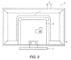
- FIG. 3 is a rear elevational view of the display device 2.
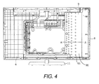
- FIG. 4 is a rear elevational view of the display device 2, illustrating the interior of the display device 2.
- FIG. 5 is a partial cross sectional view of the main components of the display device 2, taken along A-A line in FIG. 4 .
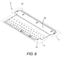
- FIG. 6 is a perspective view of the heat sink 9 in accordance with the first embodiment.
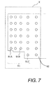
- FIG. 7 is a partial plan view of the heat sink 9 in the region X in FIG. 6 .
- FIG. 8 is a partial cross sectional view of the heat sink 9 in the region Y in FIG. 6 .
- the display device 2 is a liquid crystal television set, for example.
- the display device 2 includes a housing 4 having a front cabinet 5 and a rear frame 6 with a convex component 7, a light source 8, the heat sink 9, a rear cover 10, and a stand 11.
- the display panel 3 is disposed inside the housing 4.
- the light source 8 and the heat sink 9 are also disposed inside the housing 4.
- the housing 4 is formed by putting together the front cabinet 5 and the rear frame 6.
- the front cabinet 5 is disposed on the front side of the display device 2 (i.e., the front side of the display panel 3). As shown in FIG. 1 , the front cabinet 5 is in the shape of a picture frame, and covers the outer peripheral part of the display panel 3.
- the front cabinet 5 here is formed form plastic or another such material.
- the display panel 3 is supported by the front cabinet 5 along with a diffusing plate (not shown) and so forth, via a cell guide (not shown).
- the rear face of the display panel 3 is irradiated with light from the light source 8 (discussed below), causing an image to be displayed on the display panel 3.
- the rear frame 6 is formed from plastic or another such material, and is disposed on the rear side of the display device 2 (i.e., the rear side of the display panel 3). As shown in FIG. 2 , the rear frame 6 has a shape that bulges out slightly on the rear side of the display device 2 (i.e., the opposite side of the display device 2 from the side with the display panel 3), and covers the entire rear face of the display panel 3.
- the heat sink 9 is fastened (fixed) via a fastening member to the inner face of the rear frame 6 (i.e., the front side of the display device 2).
- the "fastening member” here is a screw or hook, for example.
- the convex component 7 is provided to the outer face of the rear frame 6.
- the convex component 7 positions the rear cover 10 (discussed below) with respect to the rear frame 6.
- the convex component 7 extends along the outer peripheral part of the rear cover 10 and protrudes slightly on the opposite side from that of the display panel 3.
- a power supply board or the like (not shown) for supplying power to the display panel 3, the light source 8 (or a plurality of light sources), etc., is attached to the center part of the rear frame 6.
- the power supply board or the like is covered by the rear cover 10 when the rear cover 10 is attached to the outer face of the rear frame 6.
- the rear cover 10 is formed from plastic or the like, and is attached to the outer face of the rear frame 6.
- the outer peripheral part of the rear cover 10 contacts with the inner peripheral part of the convex component 7, and is thereby positioning with respect to the rear frame 6.
- the stand 11 is attached to the lower end of the rear cover 10, and supports the housing 4 from below.
- the light source 8 is an edge-type LED backlight, for example, and is formed in a long, slender shape.
- the light source 8 shines light on the rear face of the display panel 3 when power is supplied from the above-mentioned power supply board.
- the light source 8 is attached to the heat sink 9. When the heat sink 9 is fastened to the rear frame 6, the light source 8 is disposed on the right edge of the display device 2 as shown in FIG. 4 , for example, and substantially parallel to the right edge.
- the light source 8 has a board 81 formed in a flat, slender shape, and a plurality of light emitting elements 82.
- the light emitting elements 82 are disposed on the board 81 in a row, spaced apart in the lengthwise direction of the board 81.
- the board 81 is formed from a metal with high thermal conductivity, such as aluminum, and is attached to an attachment component 92 of the heat sink 9 (discussed below) by double-sided tape (not shown) having high thermal conductivity.
- the heat sink 9 includes a main component 90 with a plurality of punchings 91, and the attachment component 92 to which the light source 8 is attached, and dissipates the heat generated by the attached light source 8.
- the attachment component 92 is disposed at one end of the main component 90 such that the heat sink 9 dissipates the heat generated by the light source 8.
- the heat sink has a region Y (e.g., a first region) that is defined by the attachment component 92 and the one end of the main component 90, and a region X (e.g., a second region) that is defined by the other end of the main component 90. More specifically, in the illustrated embodiment, as shown in FIG.
- the regions X and Y are laterally spaced apart from each other.
- the regions X and Y can be directly adjacent to each other.
- the region X can be a differently defined as long as the region X includes a part of the main component 90 in which all of the punchings 91 are included. In other words, the region X can range from the other end of the main component 90 to the one end of the main component 90.
- the region Y can also be a differently defined as long as the region Y includes the attachment component 92. In other words, the region Y can laterally range from the one end of the main component 90 to the location where the nearest point of the punchings 91 closest to the attachment component 92 is located.
- the attachment component 92 is formed at the one end of the heat sink 9 in the region Y.
- the attachment component 92 is formed thicker (with a higher volume) than the rest portion of the heat sink 9 other than the attachment component 92.
- the attachment component 92 is formed by hemming the one end of the heat sink 9 by stamping. More specifically, as shown in FIG. 8 , for example, the attachment component 92 is formed by hemming in which the one end of the heat sink 9 is folded outward (to the right in the drawing) of the heat sink 9. Hemming is a bending method in which a piece of sheet metal is bent at an acute angle and then pushed in further and smashed flat so that it is folded back on itself. Performing the hemming has the effect of doubling the thickness of the folded portion (i.e., increasing the volume).
- the attachment component 92 has a thickness that is twice as much as that of the rest portion of the heat sink 9 other than the attachment component 92. As shown in FIG. 8 , the attachment component 92 extends perpendicularly relative the rest portion of the heat sink 9 other than the attachment component 92.
- the attachment component 92 has a hemming part formed by stamping the one end of the main component 90.
- the attachment component 92 has a thickness that is greater than that of the one end of the main component 90.
- the attachment component 92 has a hemming part formed by outwardly folding the one end of the main component 90 that has been perpendicularly bent relative to the main component 90.
- the punchings 91 are formed in the region X that includes the other end of the heat sink 9.
- the surface area of the heat sink 9 in the region X increases as moving away from the attachment component 92. That is, the pitch of the punchings 91 decreases as moving away from the attachment component 92, as shown in FIG. 7 , for example. More specifically, as shown in FIG. 7 , the pitch in the direction intersecting the attachment component 92 decreases as moving away from the attachment component 92, in the order of the punchings 91C, the punchings 91B, and the punchings 91A.
- the result of this configuration is that the heat dissipation of the heat sink 9 increases as moving away from the light source (heat source). Also, since the punchings 91 can be formed by stamping, the surface area of the heat sink 9 in the portion (the region X) farther from the light source 8 (heat source) can be easily increased. In other words, in the illustrated embodiment, the punchings 91 are arranged denser as moving away from the attachment component 92. Thus, the main component 90 includes the punchings 91 in the region X of the heat sink 9. Also, the punchings 91 are spaced apart from each other with the pitch that decreases as moving away from the attachment component 92 (in a lateral direction from the region Y to the region X). Thus, a surface area per unit of volume of the region X of the heat sink 9 increases as moving away from the attachment component 92.
- the pitch in the direction along the attachment component 92 can instead decrease as moving away from the attachment component 92, in the order of the punchings 91C, the punchings 91B, and the punchings 91A.
- the punchings can also be such that the pitch decreases in the directions that intersect and follow the attachment component 92. Doing this allows the surface area of the heat sink 9 to increase moving away from the attachment component 92, so heat generated by the light source 8 can be more efficiently dissipated.
- the punchings 91 can also be half-punchings formed by stamping. In other words, the punchings 91 can be recesses or protrusions formed by stamping, instead of through-holes.
- the heat sink 9 has the attachment component 92 formed by hemming the one end of the heat sink 9.
- the volume of the heat sink 9 in the region X e.g., the second region
- the volume of the heat sink 9 in the region Y e.g., the first region
- the heat sink 9 has the punchings 91 formed in the region X.
- the surface area of the heat sink 9 in the region X is greater than the surface area of the heat sink 9 in the region Y.
- the region Y of the heat sink 9 has a surface area per unit of volume that is smaller than that of the region X of the heat sink 9.
- the thermal capacity of the region Y (e.g., the first region) of the heat sink 9, which is the portion nearer the light source 8 (heat source), is increased. This promotes the absorption of heat generated from the light source 8. This also promotes the dissipation of heat in the region X (e.g., the second region) of the heat sink 9, which is the portion farther away from the light source 8 (heat source). This means that the heat dissipation effect of the heat sink 9 can be enhanced without increasing the size.
- the heat dissipation effect of the heat sink 9 can be enhanced by the above configuration, a given heat dissipation effect can be maintained even if the size of the heat sink 9 is reduced.
- the effect of this is that the size of the heat sink 9 (the volume of its parts) can be kept to a minimum.
- FIG. 9 is a partial plan view of a heat sink in accordance with a modified example of the heat sink 9 in a region X corresponding to the region X in FIG. 6 .
- the pitch of the punchings 91 can be uniform (constant). This is because even if punchings 91D are formed at a uniform pitch in the region X, the surface area of the heat sink 9 in the region X will be greater than the surface area of the heat sink in the region Y (see FIG. 6 ).
- the surface area of the region X can be made greater than the surface area of the region Y, which affords a consistent effect of promoting heat dissipation by the heat sink in the region X, which is the portion farther from the light source 8 (heat source).
- the region Y of the heat sink has a surface area per unit of volume that is smaller than that of the region X of the heat sink.
- FIG. 10 is a partial cross sectional view of a heat sink in accordance with another modified example of the heat sink 9 in a region Y corresponding to the region Y in FIG. 6 .
- an attachment component 92A can be formed by hemming in which one end of the heat sink is folded inward (to the left in the drawing) of the heat sink.
- the attachment component 92A when the attachment component 92A is formed by hemming the one end of the heat sink, a radius is formed at a different sheet portion (e.g., the one end of the heat sink in the region X1 in FIG. 10 ) from the sheet portion where the light source 8 is attached, out of the two sheet portions forming the attachment component 92A.
- the radius does not interfere when the light source 8 is attached to the attachment component 92A.
- the attachment component 92A has a hemming part formed by inwardly folding the one end of the main component 90 that has been perpendicularly bent relative to the main component 90.
- a heat sink 9A in accordance with a second embodiment will now be explained.
- the parts of the second embodiment that are identical to the parts of the first embodiment will be given the same reference numerals as the parts of the first embodiment.
- the descriptions of the parts of the second embodiment that are identical to the parts of the first embodiment may be omitted for the sake of brevity.
- the heat sink 9 includes the attachment component 92 and the punchings 91 formed by stamping.
- this is not the only option.
- a different heat sink shape from that in the first embodiment will now be described through reference to the drawings.
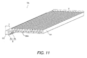
- FIG. 11 is a perspective view of the heat sink 9A in accordance with the second embodiment.
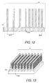
- FIG. 12 is a partial cross sectional view of the heat sink 9A in the region X in FIG. 11 .
- Those components that are the same as in FIGS. 5 to 8 are numbered the same and will not be described again in detail.
- the heat sink 9A differs from the heat sink 9 in accordance with the first embodiment shown in FIG. 6 , for example, in the shape of an attachment component 93 and the shape in the region X.
- the heat sink 9A includes a main component 90A with a plurality of fins 94, and the attachment component 93 to which the light source 8 is attached.
- the attachment component 93 is disposed at one end of the main component 90A such that the heat sink 9A dissipates the heat generated by the attached light source 8.
- the heat sink has a region Y (e.g., a first region) that is defined by the attachment component 93 and the one end of the main component 90A, and a region X (e.g., a second region) that is defined by the other end of the main component 90A. More specifically, in the illustrated embodiment, the regions X and Y can be laterally spaced apart from each other.
- the regions X and Y can also be directly adjacent to each other.
- the region X can be a differently defined as long as the region X includes a part of the main component 90A in which all of the fins 94 are included. In other words, the region X can range from the other end of the main component 90A to the one end of the main component 90A.
- the region Y can also be a differently defined as long as the region Y includes the attachment component 93. In other words, the region Y can laterally range from the one end of the main component 90 to the location where the nearest point of the fins 94 closest to the attachment component 93 is located.
- the attachment component 93 is formed at the one end of the heat sink 9A in the region Y, just as in the first embodiment. Also, the attachment component 93 is formed thicker (with a greater volume) than the rest of the heat sink 9A other than the attachment component 93.
- the attachment component 93 is formed by extrusion molding. Since the attachment component 93 can thus be formed using extrusion molding, the volume of the heat sink 9A can be easily increased in the portion (e.g., the region Y) nearer to the light source 8 (heat source). As shown in FIG. 11 , the attachment component 93 extends perpendicularly relative the rest portion of the heat sink 9 other than the attachment component 93.
- the attachment component 93 has a molding part formed by the extrusion molding.
- the attachment component 93 has a thickness that is greater than that of the one end of the main component 90A.
- the attachment component 93 perpendicularly extends from the one end of the main component 90A with respect to the main component 90A.
- the plurality of fins 94 are formed in the region X that includes the other end of the heat sink 9A.
- the fins 94 are formed by extrusion molding. With this configuration, the fins 94 can be easily formed using extrusion molding, so the surface area of the heat sink 9A can be easily increased in the portion (the region X) farther away from the light source 8 (heat source).
- the surface area of the heat sink 9A in the region X increases as moving away from the attachment component 93.
- the pitch of the fins 94 is reduced as moving away from the attachment component 93, as shown in FIG. 12 , for example. Since the surface area of the heat sink 9A thus increases as moving away from the attachment component 93, heat generated by the light source 8 can be dissipated more efficiently.
- the fins 94 are arranged denser as moving away from the attachment component 93.
- the main component 90A includes the fins 94 disposed on the region X of the heat sink 9A.
- the fins 94 are spaced apart from each other with the pitch that decreases as moving away from the attachment component 93 (in a lateral direction from the region Y to the region X).
- a surface area per unit of volume of the region X of the heat sink 9A increases as moving away from the attachment component 93.
- the heat sink 9A has the attachment component 93 that is formed thicker by extrusion molding.
- the volume of the heat sink 9A in the region X e.g., the second region
- the volume of the heat sink 9A in the region Y e.g., the first region
- the heat sink 9A has the fins 94 formed in the region X.
- the surface area of the heat sink 9A in the region X is greater than the surface area of the heat sink 9A in the region Y.
- the region Y of the heat sink 9A has a surface area per unit of volume that is smaller than that of the region X of the heat sink 9A.
- the thermal capacity of the region Y (e.g., the first region) of the heat sink 9A, which is the portion nearer the light source 8 (heat source), is increased. This promotes the absorption of heat generated from the light source 8. This also promotes the dissipation of heat in the region X (e.g., the second region) of the heat sink 9A, which is the portion farther away from the light source 8 (heat source). This means that the heat dissipation effect of the heat sink 9A can be enhanced without increasing the size.
- the heat dissipation effect of the heat sink 9A can be enhanced by the above configuration, a given heat dissipation effect can be maintained even if the size of the heat sink 9A is reduced.
- the effect of this is that the size of the heat sink 9A (the volume of its parts) can be kept to a minimum.
- the fins 94 can be formed by the same method (extrusion molding) as the attachment component 93. Thus, the above configuration can be easily formed.
- the heat sink 9A is not limited to being produced by the method discussed above.
- the attachment component 93 of the heat sink 9A can be formed so as to provide a thicker part by using a bulge produced by casting (heading).
- the fins 94 should be formed by flattening by casting (heading).
- FIG. 13 is a perspective view of a heat sink in accordance with a modified example of the heat sink 9A in a region X corresponding to the region X in FIG. 11 .
- the shape of the fins 94 is rectangular as shown in FIG. 12 , for example.
- bumps or protrusions can be formed on triangular fins 95. Forming the fins 95 in this way further increases the surface area of the heat sink in the region X. Consequently, it has the effect of further promoting the dissipation of heat from the heat sink in the region X, which is the portion farther away from the light source 8 (heat source).
- the region Y of the heat sink can have a surface area per unit of volume that is smaller than that of the region X of the heat sink.
- the present application provides a heat sink with which the heat dissipation effect can be enhanced without an increase in size.
- the present application provides a display device with this heat sink. More specifically, with the heat sink and the display device with this heat sink, the thermal capacity of the first region of the heat sink is increased in the portion closer to the light source (heat source), which promotes the absorption of heat generated from the light source, and also promotes heat dissipation in the second region of the heat sink in the portion farther away from the light source (heat source). Consequently, a heat sink can be obtained with which the heat dissipation effect can be enhanced without an increase in size.
- the heat sink and the display device with this heat sink in accordance with the above-described embodiments are provided for illustration only, not for the purpose of limiting the invention.
- the above embodiments and modification examples can be variously combined as needed and/or desired.
- the light source 8 described above is an edge-type LED backlight.
- a directly-under type of LED backlight can be used instead.
- the present invention can be applied to heat sinks and display devices with the heat sinks.
- the present invention can also be applied to organic monitors and liquid crystal monitors used for computers, television sets equipped with organic panels, liquid crystal panels, etc., and the like.
- the heat sink in accordance with one aspect of the present invention includes the main component, and the attachment component to which the light source is configured to be attached.
- the attachment component is disposed at one end of the main component such that the heat sink is configured to dissipate heat generated by the light source.
- the first region of the heat sink defined by the attachment component and the one end of the main component has a surface area per unit of volume that is smaller than that of the second region of the heat sink defined by the other end of the main component.
- the thermal capacity of the first region of the heat sink in a portion near the light source (heat source) is increased. This can promote the absorption of heat generated by the light source. This also can promote heat dissipation in the second region of the heat sink in a portion farther away from the light source (heat source). Consequently, a heat sink can be obtained in which the heat dissipation effect is improved without increasing the size.
- the heat dissipation effect can be improved. In other words, the heat dissipation effect can be maintained even if the size is reduced. This has the effect of allowing the size of the heat sink (the volume of the parts) to be kept to a minimum.
- the surface area per unit of volume of the second region increases as moving away from the attachment component.
- the heat dissipation of the heat sink can be improved in proportion to the distance from the light source (heat source).
- the attachment component can have the hemming part formed by stamping the one end of the main component.
- stamping can be used to easily increase the volume of the heat sink in the first region, which is the portion nearer to the light source (heat source).
- the attachment component can have the hemming part formed by inwardly folding the one end of the main component.
- the main component can include a plurality of punchings in the second region of the heat sink.
- the surface area of the second region of the heat sink can be easily increased in the portion farther away from the light source (heat source).
- the punchings can be spaced apart from each other with the pitch that decreases as moving away from the attachment component.
- the surface area of the heat sink can be increased as moving away from the attachment component.
- the heat generated by the light source can be more efficiently dissipated.
- the attachment component can have a molding part formed by extrusion molding.
- the attachment component can be formed using extrusion molding.
- the volume of the heat sink can be easily increased in the first region in the portion nearer to the light source (heat source).
- the main component can include a plurality of fins disposed on the second region of the heat sink.
- the fins can be easily formed using extrusion molding.
- the surface area of the heat sink in the second region can be easily increased in the portion farther away from the light source (heat source).
- the fins are spaced apart from each other with the pitch that decreases as moving away from the attachment component.
- the surface area of the heat sink can be increased as moving away from the attachment component.
- the heat generated by the light source can be more efficiently dissipated.
- the light source can include an edge-type LED backlight.
- the attachment component has a thickness that is greater than that of the one end of the main component.
- the attachment component perpendicularly extends from the one end of the main component with respect to the main component.
- the display device in accordance with one aspect of the present invention includes the light source and the heat sink.
- the light source includes a board and a plurality of light emitting elements disposed on the board.
- the heat sink includes the main component and the attachment component to which the light source is attached.
- the attachment component is disposed at one end of the main component such that the heat sink dissipates the heat generated by the light source.
- the first region of the heat sink defined by the attachment component and the one end of the main component has a surface area per unit of volume that is smaller than that of the second region of the heat sink defined by the other end of the main component.
- the present invention provides the heat sink with which the heat dissipation effect can be enhanced even though the size is reduced, as well as the display device with this heat sink.
- first and second may be used herein to describe various components these components should not be limited by these terms. These terms are only used to distinguish one component from another. Thus, for example, a first component discussed above could be termed a second component and vice-a-versa without departing from the teachings of the present invention.
- the term "attached” or “attaching”, as used herein, encompasses configurations in which an element is directly secured to another element by affixing the element directly to the other element; configurations in which the element is indirectly secured to the other element by affixing the element to the intermediate member(s) which in turn are affixed to the other element; and configurations in which one element is integral with another element, i.e.
Landscapes
- Engineering & Computer Science (AREA)
- General Engineering & Computer Science (AREA)
- Physics & Mathematics (AREA)
- Thermal Sciences (AREA)
- Microelectronics & Electronic Packaging (AREA)
- Multimedia (AREA)
- Liquid Crystal (AREA)
- Cooling Or The Like Of Electrical Apparatus (AREA)
- Cooling Or The Like Of Semiconductors Or Solid State Devices (AREA)
Applications Claiming Priority (1)
| Application Number | Priority Date | Filing Date | Title |
|---|---|---|---|
| JP2013105520A JP2014229935A (ja) | 2013-05-17 | 2013-05-17 | ヒートシンクおよびそれを備える表示装置 |
Publications (1)
| Publication Number | Publication Date |
|---|---|
| EP2804455A2 true EP2804455A2 (de) | 2014-11-19 |
Family
ID=50677979
Family Applications (1)
| Application Number | Title | Priority Date | Filing Date |
|---|---|---|---|
| EP14166672.7A Withdrawn EP2804455A2 (de) | 2013-05-17 | 2014-04-30 | Kühlkörper und Anzeigegerät mit Kühlkörper |
Country Status (3)
| Country | Link |
|---|---|
| US (1) | US20140340874A1 (de) |
| EP (1) | EP2804455A2 (de) |
| JP (1) | JP2014229935A (de) |
Citations (2)
| Publication number | Priority date | Publication date | Assignee | Title |
|---|---|---|---|---|
| JP2007311461A (ja) | 2006-05-17 | 2007-11-29 | Renesas Technology Corp | 半導体装置の製造方法 |
| JP2012129379A (ja) | 2010-12-16 | 2012-07-05 | Panasonic Corp | 放熱フィン |
Family Cites Families (8)
| Publication number | Priority date | Publication date | Assignee | Title |
|---|---|---|---|---|
| KR100769425B1 (ko) * | 2006-09-21 | 2007-10-22 | 삼성에스디아이 주식회사 | 유기전계발광 표시장치 |
| US7467882B2 (en) * | 2007-05-17 | 2008-12-23 | Kun-Jung Chang | Light-emitting diode heat-dissipating module |
| KR101365069B1 (ko) * | 2007-06-07 | 2014-02-20 | 삼성디스플레이 주식회사 | 수납 용기, 이의 제조 방법 및 이를 갖는 액정 표시 장치 |
| US7911774B2 (en) * | 2007-06-28 | 2011-03-22 | Epson Imaging Devices Corporation | Metal frame for electro-optical device having a folding portion and a seamless curved shape |
| JP4909866B2 (ja) * | 2007-10-10 | 2012-04-04 | 富士フイルム株式会社 | 面状照明装置 |
| JP2009098310A (ja) * | 2007-10-15 | 2009-05-07 | Hitachi Displays Ltd | 液晶表示装置 |
| KR20100087950A (ko) * | 2009-01-29 | 2010-08-06 | 삼성전자주식회사 | 백라이트 어셈블리 및 이를 이용한 액정표시장치 |
| JP2011221159A (ja) * | 2010-04-07 | 2011-11-04 | Seiko Epson Corp | 放熱部材、電気光学装置および電子機器 |
-
2013
- 2013-05-17 JP JP2013105520A patent/JP2014229935A/ja active Pending
-
2014
- 2014-04-16 US US14/254,622 patent/US20140340874A1/en not_active Abandoned
- 2014-04-30 EP EP14166672.7A patent/EP2804455A2/de not_active Withdrawn
Patent Citations (2)
| Publication number | Priority date | Publication date | Assignee | Title |
|---|---|---|---|---|
| JP2007311461A (ja) | 2006-05-17 | 2007-11-29 | Renesas Technology Corp | 半導体装置の製造方法 |
| JP2012129379A (ja) | 2010-12-16 | 2012-07-05 | Panasonic Corp | 放熱フィン |
Also Published As
| Publication number | Publication date |
|---|---|
| US20140340874A1 (en) | 2014-11-20 |
| JP2014229935A (ja) | 2014-12-08 |
Similar Documents
| Publication | Publication Date | Title |
|---|---|---|
| JP6195698B2 (ja) | 表示装置 | |
| JP2012221787A (ja) | 表示モジュールおよび表示装置 | |
| CN106023808B (zh) | 显示装置 | |
| US20190141281A1 (en) | Display device | |
| USRE47914E1 (en) | Display device | |
| KR102600981B1 (ko) | 디스플레이 장치 | |
| US9588364B2 (en) | Display device | |
| US9075264B2 (en) | Display device | |
| US10459270B2 (en) | Display device | |
| MX2013012560A (es) | Modelo de representacion y aparato de representacion que lo contiene. | |
| EP3264400B1 (de) | Rückplatte für verwendung in einer anzeigevorrichtung und anzeigevorrichtung mit einer solchen rückplatte | |
| EP2806305A1 (de) | Anzeigegerät | |
| EP2804455A2 (de) | Kühlkörper und Anzeigegerät mit Kühlkörper | |
| EP2804044A1 (de) | Anzeigegerät mit einteiligem Metallrahmen | |
| US10302848B2 (en) | Curved display device | |
| JP2014215452A (ja) | 液晶モジュール | |
| JP2014059955A (ja) | 照明装置およびそれを備えた表示装置 | |
| JP2021017177A (ja) | 表示装置 | |
| JP2021002562A (ja) | 表示装置 | |
| TWI454793B (zh) | 光源裝置 | |
| KR20140070858A (ko) | 조립성이 향상된 백라이트 유닛 |
Legal Events
| Date | Code | Title | Description |
|---|---|---|---|
| PUAI | Public reference made under article 153(3) epc to a published international application that has entered the european phase |
Free format text: ORIGINAL CODE: 0009012 |
|
| 17P | Request for examination filed |
Effective date: 20140430 |
|
| AK | Designated contracting states |
Kind code of ref document: A2 Designated state(s): AL AT BE BG CH CY CZ DE DK EE ES FI FR GB GR HR HU IE IS IT LI LT LU LV MC MK MT NL NO PL PT RO RS SE SI SK SM TR |
|
| AX | Request for extension of the european patent |
Extension state: BA ME |
|
| STAA | Information on the status of an ep patent application or granted ep patent |
Free format text: STATUS: THE APPLICATION HAS BEEN WITHDRAWN |
|
| 18W | Application withdrawn |
Effective date: 20160322 |