EP2804456A2 - Flüssigkeitsgekühltes Gehäuse für Schaltungsmodulvorrichtung und Verfahren zur Kühlung eines gekühlten Wärmeableitungsschaltungsmoduls - Google Patents
Flüssigkeitsgekühltes Gehäuse für Schaltungsmodulvorrichtung und Verfahren zur Kühlung eines gekühlten Wärmeableitungsschaltungsmoduls Download PDFInfo
- Publication number
- EP2804456A2 EP2804456A2 EP20140168198 EP14168198A EP2804456A2 EP 2804456 A2 EP2804456 A2 EP 2804456A2 EP 20140168198 EP20140168198 EP 20140168198 EP 14168198 A EP14168198 A EP 14168198A EP 2804456 A2 EP2804456 A2 EP 2804456A2
- Authority
- EP
- European Patent Office
- Prior art keywords
- fluid
- fluid conduit
- end portion
- interface
- enclosure
- Prior art date
- Legal status (The legal status is an assumption and is not a legal conclusion. Google has not performed a legal analysis and makes no representation as to the accuracy of the status listed.)
- Granted
Links
Images





Classifications
-
- H—ELECTRICITY
- H05—ELECTRIC TECHNIQUES NOT OTHERWISE PROVIDED FOR
- H05K—PRINTED CIRCUITS; CASINGS OR CONSTRUCTIONAL DETAILS OF ELECTRIC APPARATUS; MANUFACTURE OF ASSEMBLAGES OF ELECTRICAL COMPONENTS
- H05K7/00—Constructional details common to different types of electric apparatus
- H05K7/20—Modifications to facilitate cooling, ventilating, or heating
-
- H—ELECTRICITY
- H05—ELECTRIC TECHNIQUES NOT OTHERWISE PROVIDED FOR
- H05K—PRINTED CIRCUITS; CASINGS OR CONSTRUCTIONAL DETAILS OF ELECTRIC APPARATUS; MANUFACTURE OF ASSEMBLAGES OF ELECTRICAL COMPONENTS
- H05K7/00—Constructional details common to different types of electric apparatus
- H05K7/20—Modifications to facilitate cooling, ventilating, or heating
- H05K7/20009—Modifications to facilitate cooling, ventilating, or heating using a gaseous coolant in electronic enclosures
- H05K7/20136—Forced ventilation, e.g. by fans
- H05K7/20145—Means for directing air flow, e.g. ducts, deflectors, plenum or guides
-
- H—ELECTRICITY
- H05—ELECTRIC TECHNIQUES NOT OTHERWISE PROVIDED FOR
- H05K—PRINTED CIRCUITS; CASINGS OR CONSTRUCTIONAL DETAILS OF ELECTRIC APPARATUS; MANUFACTURE OF ASSEMBLAGES OF ELECTRICAL COMPONENTS
- H05K7/00—Constructional details common to different types of electric apparatus
- H05K7/20—Modifications to facilitate cooling, ventilating, or heating
- H05K7/20536—Modifications to facilitate cooling, ventilating, or heating for racks or cabinets of standardised dimensions, e.g. electronic racks for aircraft or telecommunication equipment
- H05K7/20554—Forced ventilation of a gaseous coolant
- H05K7/20563—Forced ventilation of a gaseous coolant within sub-racks for removing heat from electronic boards
Definitions
- the present disclosure relates generally to fluid cooled enclosure and methods of cooling conduction cooled circuit module and, more particularly, to fluid cooled enclosure for supporting conduction cooled circuit modules of a circuit module apparatus and methods of cooling conduction cooled circuit module with a fluid cooled enclosure.
- Cooling assemblies may provide fluid passages to help transfer heat away from the conduction cooled circuit modules.
- fluid cooled enclosure that can accommodate a wide range of applications with different conduction cooled circuit module arrangements.
- fluid cooled enclosure with enhanced heat transfer capabilities.
- fluid cooled enclosure that allows fabrication of fluid conduits at a reduced cost and weight.
- a fluid cooled enclosure for a circuit module apparatus comprises a housing with a first side and a second side.
- the fluid cooled enclosure further includes a fluid conduit including a first end portion positioned at the first side of the housing and a second end portion positioned at the second side of the housing.
- the fluid conduit provides a fluid coolant path between the first side and the second side of the housing.
- the fluid cooled enclosure further includes an interface block configured to be mounted with respect to the housing such that a first interface surface of the interface block engages an interface surface of the first end portion of the fluid conduit.
- the interface block includes a second interface surface configured to interface with a surface of a conduction member of a conduction cooled circuit module.
- the first interface surface and the second interface surface of the interface block face away from one another.
- the first interface surface can be substantially parallel to the second interface surface of the interface block.
- the first end portion of the fluid conduit is fabricated with a first material composition and the interface block is fabricated with a second material composition that has a higher thermal conductivity than the first material composition.
- the fluid conduit comprises an extruded fluid conduit with a substantially constant cross sectional extruded shape.
- the fluid conduit is configured for bi-directional cooling wherein the first end portion of the fluid conduit includes a first inlet port for a first fluid coolant and the second end portion of the fluid conduit includes a second inlet port for a second fluid coolant.
- the first end portion of the fluid conduit includes a second outlet port for the second fluid coolant and the second end portion of the fluid conduit includes a first outlet for the first fluid coolant.
- the fluid conduit includes a first fluid conduit for a first fluid coolant and a second fluid conduit for the second fluid coolant.
- the first fluid conduit is nested with the second fluid conduit.
- the enclosure further comprises a biasing member configured to bias a portion of a conduction member of a conduction cooled circuit module against the interface block. Once biased, the interface block is compressed between the first end portion of the fluid conduit and the portion of the conduction member of the conduction cooled circuit module.
- the interface block is integral with a conduction member of a conduction cooled circuit module.
- the first aspect may be provided alone or with any one or combination of the examples of the first aspect discussed above.
- a fluid cooled enclosure for a circuit module apparatus comprises a housing with a first side and a second side.
- the enclosure further includes a fluid conduit including a first end portion positioned at the first side of the housing and a second end portion positioned at the second side of the housing.
- the fluid conduit provides a fluid coolant path between the first side and the second side of the housing.
- the enclosure further includes an interface block configured to be mounted with respect to the first end portion of the fluid conduit.
- the first end portion of the fluid conduit is fabricated with a first material composition and the interface block is fabricated with a second material composition that has a higher thermal conductivity than the first material composition.
- a fluid cooled enclosure for a circuit module apparatus comprises a housing with a first side and a second side.
- the enclosure includes a fluid conduit configured for bi-directional cooling, wherein the fluid conduit includes a first end portion positioned at the first side of the housing and a second end portion positioned at the second side of the housing.
- the fluid conduit provides bi-directional fluid coolant paths between the first side and the second side of the housing.
- the first end portion of the fluid conduit includes a first inlet port for a first fluid coolant and the second end portion of the fluid conduit includes a second inlet port for a second fluid coolant.
- the second end portion of the fluid conduit can further include a first outlet for the first fluid coolant and the first end portion of the fluid conduit can further include a second outlet port for the second fluid coolant.
- the fluid conduit can include a first fluid conduit for a first fluid coolant and a second fluid conduit for the second fluid coolant.
- the first fluid conduit may be nested with the second fluid conduit.
- the third aspect may be provided alone or with any one or combination of the examples of the third aspect discussed above.
- a method of cooling a conduction cooled circuit module comprises the step (I) of providing a fluid cooled enclosure with a fluid conduit and the step (II) of mounting an interface block to the conduction cooled circuit module such that a portion of a conduction member of the conduction cooled module engages an interface surface of the interface block.
- the method further includes the step (III) of mounting the interface block with respect to the fluid conduit such that another interface surface of the interface block engages an interface surface of the fluid conduit.
- the method also includes the step (IV) of cooling electrical circuits of the conduction cooled circuit module by flowing fluid coolant through the fluid conduit, wherein heat is transferred from the electrical circuits, through the conduction member, through the interface block and carried away by the fluid coolant.
- the method further includes the step of selecting an interface block including a desired heat transfer characteristic for mounting during step (II).
- step (II) occurs before step (III).
- the fourth aspect may be provided alone or with any one or combination of the examples of the fourth aspect discussed above.
- fluid cooled enclosure may be provided that may simultaneously support and cool one or more conduction cooled circuit modules.
- a plurality of circuit modules of relatively high power can be supported together in a relatively compact arrangement while providing sufficient cooling of the conduction cooled circuit modules to prevent overheating that might otherwise occur without sufficient cooling.
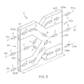
- FIG. 1 illustrates just one example of a fluid cooled enclosure 101 for a circuit module apparatus 103.
- the fluid cooled enclosure 101 includes a housing 105 that may facilitate support of the circuit modules while protecting the circuit modules from damage and/or contamination from environmental conditions.
- the housing 105 can comprise a first side 107 comprising a first lateral side and a second side 109 comprising a second lateral side.
- the first and second sides can be selected from any combination of the first lateral side 107, the second lateral side 109, a top side 113, a bottom side 115, a front side 117 and a rear side 119.
- the first and second side can comprise opposite sides comprising the first and second lateral sides 107, 109; the top and bottom sides 113, 115; or the front and rear sides 117, 119.
- the first and second sides can comprise any combination of adjacent sides of the housing 105.
- the housing 105 is shown as a box-like configuration with six total sides although other housing configurations may have more or less than six sides in further examples.
- the sides of the housing are illustrated as substantially planar sides, further shapes may be provided in further examples.
- the housing may comprise a cylindrical housing where the sides may comprise any combination of a front end, a rear end, one of the cylindrical lateral sides, the cylindrical top or the cylindrical bottom of the cylindrical housing.
- the fluid cooled enclosure 101 further includes a plurality of fluid conduits 111 although a single fluid conduit may be provided in further examples.
- Fluid conduits may be designed to accommodate various fluid coolants such as liquid or gas fluid coolants.
- the fluid conduit may accommodate air being passed through the fluid conduit to cool the system.
- liquid may be used to enhance heat transfer from the conduction cooled circuit module when compared to air cooled systems.
- each fluid conduit 111 is substantially identical with one another although fluid conduits may have different configurations in further examples.
- the fluid conduit 111 can include a first end portion 201 positioned at the first side comprising the first lateral side 107 of the housing 105 and a second end portion 203 positioned at the second side comprising the second lateral side 109 of the housing 105.
- the fluid conduit 111 can optionally be configured for bi-directional cooling wherein fluid flow can be provided with bi-directional fluid coolant paths between the first side 107 and the second side 109 of the housing 105.
- the example fluid conduit 111 provides a first fluid coolant path 301, 301a, 301b between the first side 107 and the second side 109 of the housing 105.
- a first fluid coolant may pass along the first fluid coolant path 301, 301a, 301b in a direction from the first side 107 to the second side 109 of the housing.
- the example fluid conduit 111 can further provide a second fluid coolant path 311, 311a, 311b between the first side 107 and the second side 109 of the housing 105. As represented by the arrows designated "B" in FIG. 3 , a second fluid coolant may pass along the second fluid coolant path 311, 311a, 311b in a direction from the second side 109 to the first side 107 of the housing 105.
- the first end portion 201 of the fluid conduit 111 can include a first inlet port 303 for the first fluid coolant and the second end portion 203 of the fluid conduit 111 can include a second inlet port 305 for the second fluid coolant.
- the second end portion 203 of the fluid conduit 111 includes a first outlet port, for example, that may be optionally split into separate portions.
- the first outlet port includes a first portion 309a and a second portion 309b.
- the first end portion 201 can include a second outlet port, for example, that may also be optionally split into separate portions. For instance, as also shown in FIG.
- the second outlet port includes a first portion 307a and a second portion 307b.
- Splitting the first and second outlet port can provide one example configuration that allows the fluid conduit 111 to include a first fluid conduit 401 and a second fluid conduit 403 (see FIG. 4 ) that can be nested together as shown in FIG. 3 .
- the first fluid conduit 401 can comprise a Y-shaped conduit including an inlet branch 405 including the first inlet port 303 and two outlet branches 407a, 407b that respectively include the first and second portions 309a, 309b of the first outlet port.
- the second fluid conduit 403 can also comprise a similar Y-shaped conduit with an inlet branch 409 including the second inlet port 305 and two outlet branches 411a, 411b that respectively include the first and second portions 307a, 307b of the second outlet port.
- the outlet branches each fluid conduit can include recessed portions 413a, 413b configured to receive a portion of the outlet branches of the other fluid conduit when the fluid conduits 401, 403 are nested together as shown in FIG. 3 .
- the first fluid conduit 401 can be nested with the second fluid conduit 403 by inverting the Y-shaped conduits and aligning the conduits such that the recessed portions 413a, 413b of each conduit face one another.
- the fluid conduits 401, 403 are nested together as shown in FIG. 3 , wherein the inlet branch 405 of the first conduit 401 is straddled by the outlet branches 411a, 411b of the second conduit 403 while the inlet branch 409 of the second conduit 403 is straddled by the outlet branches 407a, 407b of the first conduit 401.
- first conduit 401 being nested with the second conduit 403 can provide a compact design permitting a reduced cooling footprint area while allowing bidirectional cooling from separate fluid coolant streams. Moreover, providing bi-directional cooling can permit relatively favorable cooling at both ends of the fluid conduit when compared to uni-directional cooling.
- first fluid coolant is designed to enter the first inlet port 303 at a lower temperature than the first fluid coolant exiting the second fluid port of the first conduit 401.
- the second fluid coolant is designed to enter the second inlet port 305 at a lower temperature than the second fluid coolant exiting the second fluid port of the second conduit 403.
- Fluid conduits throughout the disclosure can be fabricated by injection molding, 3D printing, extrusion or other fabrication techniques.
- the fluid conduits 401, 403 may be fabricated by 3D printing of fluid using, for example, laser sintering or other 3D printing techniques.
- FIG. 1 illustrates a potential arrangement of a plurality of the fluid conduits 111 arranged to be spaced apart from one another along an axis of the housing 105.
- the first side 107 can include elongated openings 121 aligned with elongated openings 123 in the second side 109.
- the elongated openings 121 in the first side 107 are configured to receive the first end portion 201 of the fluid conduits while the elongated openings 123 in the second side 109 are configured to receive the second end portion 203.
- the end edges 201a of the first end portion 201 can be flush with respect to the outer surface 205 of the first side 107 of the housing while the end edges 203a of the second end portion 203 can be flush with respect to the outer surface 207 of the second side 109 of the housing.
- a first U-shaped conduit 127 may be mounted with respect to the first side 107 with opposed walls 129a, 129b extending across respective intermediate portions 125a, 125b of the first end portions 201 of the fluid conduits 111 to place the first inlet ports 303 in fluid communication with one another.
- a second U-shaped conduit 131 can also be mounted with respect to the second side 109 with opposed walls 133a, 133b that likewise extends across respective intermediate portions of the second end portions 203 of the fluid conduits to place the second inlet ports 305 in fluid communication with one another.
- a first fluid coolant stream 135 can enter an inlet of the first U-shaped conduit 127.
- the first fluid coolant stream 135 is then divided such that portions enter respective first inlets 303 of the fluid conduits 111.
- the fluid is then further divided to exit portions 309a, 309b of the first outlet port to be discharged above and below the second U-shaped conduit 131.
- a second fluid coolant stream 137 can enter an inlet of the second U-shaped conduit 131.
- the second fluid coolant stream 137 is then divided such that portions enter respective second inlets 305 of the fluid conduits 111.
- the fluid is then further divided to second portions 307a, 307b of the second outlet port to be discharged above and below the first U-shaped conduit 127.
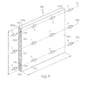
- FIG. 5 illustrates another example of a fluid cooled enclosure 501 for a circuit module apparatus 503.
- the fluid cooled enclosure 501 can include the housing 105 discussed above although other configurations may be used in further examples.
- the fluid cooled enclosure 501 further includes a plurality of fluid conduits 505 although a single fluid conduit may be provided in further examples. As shown, each fluid conduit 505 is substantially identical with one another although fluid conduits may have different configurations in further examples. As shown in FIG. 6 , the fluid conduit 505 can include a first end portion 601 positioned at the first side 107 comprising the first lateral side of the housing 105 and a second end portion 603 positioned at the second side 109 comprising the second lateral side of the housing 105.
- FIG. 5 illustrates a potential arrangement of a plurality of the fluid conduits 505 arranged to be spaced apart from one another along the axis of the housing 105.
- the elongated openings 121 in the first side 107 are configured to receive the first end portion 601 of the fluid conduits 505 while the elongated openings 123 in the second side 109 are configured to receive the second end portion 603.
- end edges 601a of the first end portion 201 can be flush with respect to the outer surface 205 of the first side 107 of the housing while end edges 203a of the second end portion 603 can be flush with respect to the outer surface 207 of the second side 109 of the housing 105.
- the fluid conduit 505 can optionally be configured for uni-directional cooling wherein fluid flow can be provided with one or more unidirectional fluid coolant paths between the first side 107 and the second side 109 of the housing 105.
- the example fluid conduit 505 provides a first fluid coolant path 701 between the first side 107 and the second side 109 of the housing 105.
- a first fluid coolant may pass along the first fluid coolant path 701 in a direction from the first side 107 to the second side 109 of the housing.
- the fluid conduit 505 includes a single fluid path.
- the single fluid path may be provided with one or more optional fins 703 that may extend partially or entirely across the entire length "L" of the fluid conduit 505.
- the fins 703, if provided, can help facilitate convection heat transfer from the walls of the fluid conduit 505 to the first fluid coolant stream.
- the walls may be substantially free from fins which may be desired to simplify the fluid conduit 505 while maintaining sufficient heat transfer in some applications.
- the fluid conduit 505 may include a second fluid coolant path 705 that may be isolated from the first fluid coolant path 701 by way of partition walls 707 that extend partially, or entirely, along the length "L" of the fluid conduit 505.
- Isolating the fluid coolant paths may be desired to help control cooling at different portions along the height " H " of the fluid conduit 505.
- a plurality of additional fluid coolant paths 709 may also be defined, for example, by way of the partition walls 707.
- the additional fluid coolant paths 709 may be defined by the partition walls 707 without free-ended fins extending within the fluid coolant paths 709.
- the partition walls 707 may be spaced close enough together to help facilitate conduction heat transfer from the major walls of the fluid conduit to the fluid stream.
- the partition walls 707 may substantially increase the structural strength and rigidity of the fluid conduit 505.
- a single fluid coolant path may be provided including any of the features discussed above.
- the fluid conduit may be designed with a single fluid coolant path defined by the two major walls 711a, 711b and the two end walls 713a, 713b.
- the single fluid coolant path may optionally include one or more of the fins 703 although the inner surfaces of the major walls and end walls may be provided without fins in further examples.
- the fluid conduit may be provided entirely by the plurality of fluid coolant paths defined by the partition walls 707.
- the fluid conduit can provide the above-referenced uni-directional cooling. Unidirectional cooling can simplify the fluid conduit design while providing sufficient heat transfer capabilities depending on the particular application.
- unidirectional cooling may be easily achieved by inexpensively forming the fluid conduit 505 by an extrusion process wherein the extruded conduit is provided with a substantially constant cross-sectional extruded shape.
- the cross sectional shape illustrated at the first end portion 601 of the fluid conduit 505 extends continuously along the entire length "L" of the fluid conduit 505 such that the cross-sectional extruded shape illustrated at the first end portion 601 shown in FIG. 7 exists at every cross section taken parallel to end edges 601a of the first end portion 601.
- providing the fluid conduit 505 as the illustrated extruded fluid conduit with a substantially constant cross sectional extruded shape can reduce the cost of producing the fluid conduit 505 and costs of installing the fluid conduit to the housing while still providing sufficient cooling capacity.
- a first U-shaped conduit 507 may be mounted with respect to the first side 107 with opposed walls 507a, 507b extending to the first side 107 of the housing 105 to place inlet ports 605 of the fluid conduits 505 in fluid communication with one another.
- a second U-shaped conduit 509 can also be mounted with respect to the second side 109 with opposed walls 509a, 509b that likewise extend to the second side 109 of the housing 105 to place outlet ports 607 of the second end portions 603 of the fluid conduits to place outlet ports 607 of the fluid conduits 505 in fluid communication with one another.
- a first fluid coolant stream 511 can enter an inlet of the first U-shaped conduit 507.
- the first fluid coolant stream 511 is then divided such that portions enter respective first inlets 605 of the fluid conduits 505.
- the fluid then travels to outlet ports 607 to be received in the second U-shaped conduit 509 and carried away as fluid stream 513 exiting the fluid conduit.
- the fluid cooled enclosure 101, 501 further includes at least one interface block configured to be mounted with respect to the housing.
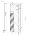
- FIGS. 8 and 9 illustrate example interface blocks 801, 901 that may be used in accordance with aspects of the disclosure with the understanding that alternative interface blocks may be provided in further examples.
- features of the example interface blocks 801, 901 are shown with respect to the second end portions 203, 603 with the understanding that similar or identical interface blocks may be provided at the first end portions 201, 601.
- the end configuration associated with the first end portion 201 may comprise a mirror image of the end configurations of the second end portions 203, 603.
- a detailed discussion of the interface blocks 801, 901 will be described with reference to the second end portions 203, 603 with the understanding that a similar or identical mirror image configuration may be provided at the first end portions 201, 601.
- one example interface block 801 is mounted with respect to the housing 105 such that a first interface surface 803 of the interface block 801 engages an interface surface 805 of the first end portion 201 of the fluid conduit 111.
- the first interface surface 803 very closely matches the interface surface 805 of the fluid conduit 111 to provide excellent conductive heat transfer therebetween.
- the first interface surface 803 can be machined to be extremely flat or may be nickel plated or otherwise processed to be extremely flat.
- the first interface surface 803 can be provided with a flat surface having a reduced surface roughness (Ra), for example, from about 0.2 ⁇ m to about 1.5 ⁇ m to reduce or eliminate potential air gaps between the first interface surface 803 and the interface surface 805.
- Ra surface roughness
- the surface roughness can be selected as a heat transfer characteristic to provide the desired heat transfer efficiency for the particular cooling application.
- the surface roughness can be left relatively rough to reduce costs associate with machining, coating or other processing techniques while still providing a desired cooling capacity.
- the surface roughness can be reduced to enhance heat transfer in applications where a higher cooling capacity is desired.
- At least one of the first end portion 201, 601 and the second end portion 203, 603 of the fluid conduit 111, 505 may be fabricated with a first material composition and the interface block 801 may be fabricated with a second material composition that has a higher thermal conductivity than the first material composition although the thermal conductivity may be substantially the same in further examples.
- the second material composition of the interface block 801 can have a thermal conductivity that is greater than or equal to 200 W/m ⁇ K.
- the first material composition of the fluid conduit can comprise aluminum with a thermal conductivity of 180 W/m ⁇ K while the second material composition of the interface block 801 can comprise copper with a thermal conductivity of 400 W/m ⁇ K or a composite material with a thermal conductivity of from about 600 W/m ⁇ K to about 2000 W/m ⁇ K.
- a composite material may comprise a carbon fiber matrix fused with aluminum or copper although other composite materials may be provided in further examples.
- the interface block 801 may be fabricated from a material that is preselected to provide the desired heat transfer characteristic by adjusting the thermal conductivity of the interface block 801. A higher heat transfer conductivity for the second material of the interface block may be selected to accommodate high power applications requiring enhanced thermal conductivity while a lower heat transfer conductivity for the second material of the interface block may be selected to accommodate lower power applications.
- the interface block 801 may have a width "W" that is substantially less than the length "L" of the fluid conduit.
- the width can be maximized to provide enhanced heat transfer while being reduced to the extent necessary to maintain the desired bearing pressure of the first interface surface 803 against the interface surface 805.
- the length of the interface block 801 can be selected to extend along a substantial portion or the entire height " H " of the fluid conduit.
- the width "W" of the interface block 801 can be selected to provide the desired clamping pressure selected for the particular application and can range, for example, from about 0.1 MPa to about 8 MPa, such as from about 0.5 MPa to about 2 MPa, such as from about 0.1 MPa to about 1 MPa.
- the width of the interface block 801 may be preselected to provide the desired heat transfer characteristic by adjusting the contact bearing pressure of the interface block against the fluid conduit.
- the interface block 801 can further include a second interface surface 807 configured to interface with a surface 809 of a conduction member 811 of a conduction cooled circuit module 813.
- the first interface surface 803 and the second interface 807 surface of the interface block 801 face away from one another and, in some examples, the first interface surface 803 is substantially parallel to the second interface surface 807 of the interface block.
- Providing the interface block with substantially parallel surfaces can be effective to accommodate a conduction member 811 comprising a conduction plate wherein the surface 809 is substantially flat and extends along a plane. As such, both ends of the conduction plate may more effectively abut corresponding second interface surfaces 807 of respective interface blocks 801 mounted at the first end portion and the second end portion of the fluid conduits 111, 505.
- an optional layer of thermal interface material (TIM) 808 may be provided.
- the material may comprise a phase change material configured to fill interstitial voids during an initial heat cycle that operates to integrate the second interface surface 807 with the surface 809 of the conduction member 811.
- TIM thermal interface material
- providing a desired level of thermal conductivity at the interface between the conduction member 811 of the conduction cooled circuit module 813 and the interface block 801 can be preselected to provide the desired heat transfer characteristic.
- the interface block 801 is mounted to the conduction member 811 of a conduction cooled circuit module 813 which is then in turn mounted to the housing.
- the interface block 801 is configured to be mounted with respect to the housing indirectly by way of the circuit module 813. Such a configuration may be beneficial to allow a circuit module to be easily removed from the housing and replaced with another module possibly having a different interface block configuration to address a unique power requirement of the circuit module 813.
- the interface block 801 may optionally be configured to be mounted with respect to the housing by being directly mounted to the housing.
- FIGS. 8 and 9 each show examples wherein the interface block 801, 901 is not integral with the first or second end portion of the fluid conduits.
- Providing the interface blocks that are separate from the end portions of the fluid conduits can allow formation of the fluid conduits by way of an extrusion process wherein the extruded conduit is provided with a substantially constant cross-sectional extruded shape.
- the interface block 901 may optionally be integral with the conduction member 811 of the conduction cooled circuit module 813. Providing an integral interface block 901 may be desired to reduce the number of parts.
- FIG. 8 illustrates examples where the interface block 801 is not integral with the conduction member 811.
- Providing a separate interface block 801 that is later integrated with the surface 809 of the conduction member 811 can allow retrofitting of various existing conduction cooled circuit modules 813 with conduction members 811 comprising substantially flat plates. Moreover, providing separate interface blocks 801 can allow tuning of the enclosure to tailor the enclosure to accommodate a particular conduction cooled circuit module with power requirements for the electronics on the circuit boards of the circuit modules.
- the enclosure can optionally comprise a biasing member 815 configured to bias a portion 817 of a conduction member 811 of a conduction cooled circuit module 813 against the interface block 801 such that the interface block is compressed between the first end portion 201 of the fluid conduit and the portion 817 of the conduction member 811 of the conduction cooled circuit module 813.
- the biasing member 815 can comprise a wedgelock expander although captive fasteners with springs or other biasing devices may be provided in further examples.
- the biasing member 815 can be designed to apply a predetermined force to the allow the interface block to apply the desired bearing pressure against the fluid conduit sufficiently reduce resistance to heat transfer from the conduction member 811 to the fluid conduit.
- the conduction cooled circuit module 831 includes a circuit board 816 with electrical components 818, such as central processing units, or other electrical components mounted on the circuit board 816.
- the conduction member 811 such as the illustrated conduction plate may be mounted to the circuit board such that heat from the electrical components may freely travel to the conduction member 811.
- the conduction member may comprise metal or composites that facilitate conduction of heat away from the electrical components 818.
- the conduction member 811 may span a substantial portion of the length "L" of the fluid conduit, such as substantially the entire length "L” to maximize heat transfer from the conduction member 811 to the fluid conduit.
- the method can include the step of providing the fluid cooled enclosure 101, 501 with the fluid conduit 111, 505.
- the interface block 801 can be mounted to the conduction cooled circuit module 813 such that a portion of a conduction member 811 of the conduction cooled module 813 engages the second interface surface 807 of the interface block 801.
- the method can then include the step of mounting the interface block 801 with respect to the fluid conduit 111, 505 such that the first interface surface 803 of the interface block 801 engages an interface surface 805 of the fluid conduit 111, 505.
- the interface block may be mounted to the conduction cooled circuit module prior to mounting the interface block with respect to the fluid conduit.
- the interface block may be mounted with respect to the fluid conduit prior to mounting the interface block to the conduction cooled circuit module.
- the method can further include the step of cooling electrical circuits of the conduction cooled circuit module 813 by flowing fluid coolant through the fluid conduit, wherein heat is transferred from the electrical circuits, through the conduction member, through the interface block and carried away by the fluid coolant.
- the method can comprise the step of selecting an interface block including a desired heat transfer characteristic for mounting the interface block with respect to the fluid conduit.
- an interface block may include a desired surface roughness for the first interface surface 803, a desired width "W", a desired material composition used to fabricate the interface block or other characteristics wherein the thermal resistance provided by the interface block may be dialed in to a particular thermal cooling configuration.
- heat transfer characteristics of the interface blocks may be tailored to accommodate the particular conduction cooled circuit module 813.
- Lower power modules may require lower conductivity and may therefore select interface blocks comprising materials with a relatively low thermal conductivity (e.g., aluminum), comprise interface blocks with relatively small widths "W” or relatively rough interface surfaces.
- Higher power modules may also be handled by providing the enclosure with a relatively high conductivity by selecting an interface block comprising materials with a relatively high thermal conductivity (e.g., copper, composite materials with high conductivity), interface blocks that have relatively wide widths "W” with sufficient bearing pressure, or relatively smooth interface surfaces.
- Fluid cooled enclosure may accommodate fluid coolant sources such as air (or other gas), liquid, or vapor to cool 200W+ systems such as conduction cooled circuit modules 813 with circuits comprising two 70W processors or other relatively high power electrical components.
- the fluid cooled enclosure of the present disclosure can provide a relatively rugged design to accommodate a wide range of conduction cooled circuit modules having different cooling requirements.
- Example embodiments can include the fluid conduit 505 that may be extruded with little or no post-machining of the exterior surfaces. Such fluid conduits 505 may be provided with a constant cross-sectional size and shape along the length to provide relatively inexpensive production of fluid conduits for fabricating the fluid cooled enclosure.
- Example embodiments further include fluid cooled enclosure that provide the housing 105 with openings 121 that may receive the end portions of the fluid conduits and bond the end portions to provide a fluid tight seal to prevent leakage of the fluid coolant into the interior of the housing outside the fluid conduit.
- Example embodiments further optionally provide a fluid conduit 111 configured for bi-directional cooling arrangement that can provide superior cooling when compared to uni-directional designs.
- the bi-directional cooling arrangement can allow high powered circuit components to be located near the card edges corresponding to the end portions 201, 203 of the fluid conduit 111. As such, both card edges can provide superior cooling efficiency when compared to uni-directional designs that may only provide superior cooling at one edge of the conduction cooled circuit module.
- the interface blocks can be attached to the card edges to allow tailoring of the thermal resistance between the circuit module edges and the fluid conduit.
- the width "W" of the interface block can be selected depending on the power of the modules and therefore the amount of cooling needed. Wider blocks will involve a larger surface area and may therefore be used to accommodate higher power configurations while narrower blocks can be used with lower power modules. Materials having higher thermal conductivity may be used to fabricate the interface blocks in applications with high power requirements while lower thermal conductivity may be used to fabricate interface blocks in applications with lower power requirements.
- High conductivity composites with a thermal conductivity of greater than 400 W/m ⁇ K, copper (about 400 W/m ⁇ K) or aluminum (about 200 W/m ⁇ K) may optionally be used to fabricate the interface blocks depending on the desired cooling requirements of the particular application. Still further, the surface finish of the interface blocks may be tailored to the circuit module power. Finishes with low thermal contact resistance (e.g., nickel plating) may be used for higher power modules, whereas other finishes like anodizing and chemical conversion may be used for lower power modules.
- the layer of thermal interface material (TIM) 808 may be used to facilitate alignment of the contact surface of the interface block while reducing thermal contact resistance between the conduction member 811 and the interface block.
- a resilient heat transfer member 819 may be provided to facilitate heat transfer between central portions of the conduction member 811 and the fluid conduit.
- the resilient heat transfer member 819 is designed to provide a bridge between the space that may otherwise exist between the back surface of the conduction member and the fluid conduit without contributing substantially to the bearing stress against the fluid conduit. As such, pressure may be maintained between the first interface surface 803 of the interface block 801 and the interface surface 805 of the fluid conduit.
- a fluid cooled enclosure 101, 501 for a circuit module apparatus 103, 503 comprises a housing 105 with a first side 107 and a second side 109.
- the fluid cooled enclosure further comprises a fluid conduit 111, 401, 403, 505 including a first end portion 201, 601 positioned at the first side of the housing and a second end portion 203, 603 positioned at the second side of the housing.
- the fluid conduit provides a fluid coolant path 301, 301a, 301b, 311, 311a, 311b, 701, 705, 709 between the first side and the second side of the housing.
- the fluid cooled enclosure further comprises an interface block 801, 901 configured to be mounted with respect to the housing such that a first interface surface 803 of the interface block engages an interface surface 805 of the first end portion of the fluid conduit.
- the example E1 may provide the interface block 801 with a second interface surface 807 configured to interface with a surface 809 of a conduction member 811 of a conduction cooled circuit module 813.
- E3 the example E2 may be provided wherein the first interface surface and the second interface surface of the interface block face away from one another.
- example E2 or E3 may be provided wherein the first interface surface is substantially parallel to the second interface surface of the interface block.
- the example E1 may be provided wherein the interface block is integral with a conduction member 811 of a conduction cooled circuit module 813.
- any one of the examples E1-E5 may be provided wherein the first end portion of the fluid conduit is fabricated with a first material composition and the interface block is fabricated with a second material composition that has a higher thermal conductivity than the first material composition.
- any one of the examples E1-E6 may further comprise a biasing member 815 configured to bias a portion 817 of a conduction member 811 of a conduction cooled circuit module 813 against the interface block such that the interface block is compressed between the first end portion of the fluid conduit and the portion of the conduction member of the conduction cooled circuit module.
- any one of the examples E1-E7 may be provided wherein the fluid conduit 505 comprises an extruded fluid conduit with a substantially constant cross sectional extruded shape.
- a fluid cooled enclosure 101 for a circuit module apparatus 103 comprises a housing 105 with a first side 107 and a second side 109.
- the fluid cooled enclosure further comprises a fluid conduit 111, 401, 403 configured for bi-directional cooling.
- the fluid conduit includes a first end portion 201 positioned at the first side of the housing and a second end portion 203 positioned at the second side of the housing.
- the fluid conduit provides bi-directional fluid coolant paths 301, 301a, 301b, 311, 311a, 311b between the first side and the second side of the housing.
- the example E9 is provided wherein the first end portion of the fluid conduit includes a first inlet port 303 for a first fluid coolant and the second end portion of the fluid conduit includes a second inlet port 305 for a second fluid coolant.
- any one of examples E1-E7 may be provided wherein the fluid conduit 111, 401, 403 is configured for bi-directional cooling wherein the first end portion of the fluid conduit includes a first inlet port 303 for a first fluid coolant and the second end portion of the fluid conduit includes a second inlet port 305 for a second fluid coolant.
- any one of examples E9-E11 may be provided wherein the second end portion of the fluid conduit includes a first outlet for the first fluid coolant and the first end portion of the fluid conduit includes a second outlet port for the second fluid coolant.
- any one of examples E9-E12 may be provided wherein the first end portion of the fluid conduit includes a second outlet port 307a, 307b for the second fluid coolant and the second end portion of the fluid conduit includes a first outlet 309a, 309b for the first fluid coolant.
- any one of examples E10-E13 may be provided wherein the fluid conduit 401, 403 includes a first fluid conduit 401 for a first fluid coolant and a second fluid conduit 403 for the second fluid coolant.
- the example of E14 may be provided wherein the first fluid conduit is nested with the second fluid conduit.
- a method of cooling a conduction cooled circuit module 813 comprises the step (I) of providing a fluid cooled enclosure 101, 501 with a fluid conduit 111, 401, 403, 505 and the step (II) of mounting an interface block 801, 901 to the conduction cooled circuit module such that a portion 817 of a conduction member 811 of the conduction cooled module engages an interface surface 803 of the interface block.
- the method further includes the step (III) of mounting the interface block with respect to the fluid conduit such that another interface surface 803 of the interface block engages an interface surface 805 of the fluid conduit.
- the method still further includes the step (IV) of cooling electrical circuits of the conduction cooled circuit module by flowing fluid coolant through the fluid conduit, wherein heat is transferred from the electrical circuits, through the conduction member, through the interface block and carried away by the fluid coolant.
- the method of example E16 further comprises the step of selecting an interface block including a desired heat transfer characteristic for mounting during step (II).
- step (II) occurs before step (III).
Landscapes
- Engineering & Computer Science (AREA)
- Microelectronics & Electronic Packaging (AREA)
- Physics & Mathematics (AREA)
- Thermal Sciences (AREA)
- Aviation & Aerospace Engineering (AREA)
- Cooling Or The Like Of Semiconductors Or Solid State Devices (AREA)
- Cooling Or The Like Of Electrical Apparatus (AREA)
Applications Claiming Priority (2)
| Application Number | Priority Date | Filing Date | Title |
|---|---|---|---|
| US201361823615P | 2013-05-15 | 2013-05-15 | |
| US14/245,570 US9526191B2 (en) | 2013-05-15 | 2014-04-04 | Fluid cooled enclosure for circuit module apparatus and methods of cooling a conduction cooled circuit module |
Publications (3)
| Publication Number | Publication Date |
|---|---|
| EP2804456A2 true EP2804456A2 (de) | 2014-11-19 |
| EP2804456A3 EP2804456A3 (de) | 2015-06-03 |
| EP2804456B1 EP2804456B1 (de) | 2019-07-31 |
Family
ID=50771417
Family Applications (1)
| Application Number | Title | Priority Date | Filing Date |
|---|---|---|---|
| EP14168198.1A Active EP2804456B1 (de) | 2013-05-15 | 2014-05-13 | Flüssigkeitsgekühltes Gehäuse für Schaltungsmodulvorrichtung |
Country Status (2)
| Country | Link |
|---|---|
| US (1) | US9526191B2 (de) |
| EP (1) | EP2804456B1 (de) |
Cited By (2)
| Publication number | Priority date | Publication date | Assignee | Title |
|---|---|---|---|---|
| WO2016189351A1 (en) * | 2015-05-25 | 2016-12-01 | Aselsan Elektronik Sanayi Ve Ticaret Anonim Sirketi | A waterproof cooling device |
| US9960101B2 (en) | 2015-06-04 | 2018-05-01 | Raytheon Company | Micro-hoses for integrated circuit and device level cooling |
Families Citing this family (26)
| Publication number | Priority date | Publication date | Assignee | Title |
|---|---|---|---|---|
| US10415903B2 (en) * | 2014-10-15 | 2019-09-17 | Hamilton Sundstrand Corporation | Prevention of cooling flow blockage |
| US20180018000A1 (en) * | 2015-01-30 | 2018-01-18 | Hewlett Packard Enterprise Development Lp | Integrated liquid cooling of a server system |
| US10222106B2 (en) * | 2015-03-31 | 2019-03-05 | The Boeing Company | Condenser apparatus and method |
| US9538691B2 (en) * | 2015-04-15 | 2017-01-03 | Ford Global Technologies, Llc | Power inverter for a vehicle |
| US10386127B2 (en) * | 2015-09-09 | 2019-08-20 | General Electric Company | Thermal management system |
| US9967978B1 (en) * | 2016-03-03 | 2018-05-08 | Raytheon Company | Methods and apparatus for a rail-mounted array assembly |
| US10017073B2 (en) | 2016-03-09 | 2018-07-10 | Ford Global Technologies, Llc | Coolant channels for power module assemblies |
| US9950628B2 (en) * | 2016-03-09 | 2018-04-24 | Ford Global Technologies, Llc | Power-module assembly with dummy module |
| US9961808B2 (en) | 2016-03-09 | 2018-05-01 | Ford Global Technologies, Llc | Power electronics system |
| US10209009B2 (en) | 2016-06-21 | 2019-02-19 | General Electric Company | Heat exchanger including passageways |
| US10605544B2 (en) | 2016-07-08 | 2020-03-31 | Hamilton Sundstrand Corporation | Heat exchanger with interleaved passages |
| CN108075672B (zh) | 2016-11-18 | 2019-11-22 | 比亚迪股份有限公司 | 负载控制器及具有该负载控制器的电动汽车 |
| US10645845B2 (en) * | 2018-04-12 | 2020-05-05 | Northrop Grumman Systems Corporation | Forced flow cooling temperature control method, system, and apparatus |
| US10954814B2 (en) | 2018-09-26 | 2021-03-23 | Honeywell International Inc. | System with thin walled cooling plate for an electronic enclosure |
| US10908657B2 (en) * | 2019-02-15 | 2021-02-02 | Pensando Systems Inc. | Methods and systems for thermal control |
| US10772188B1 (en) * | 2019-06-11 | 2020-09-08 | International Business Machines Corporation | Stiffener cooling structure |
| US11260976B2 (en) | 2019-11-15 | 2022-03-01 | General Electric Company | System for reducing thermal stresses in a leading edge of a high speed vehicle |
| US11427330B2 (en) | 2019-11-15 | 2022-08-30 | General Electric Company | System and method for cooling a leading edge of a high speed vehicle |
| US11260953B2 (en) | 2019-11-15 | 2022-03-01 | General Electric Company | System and method for cooling a leading edge of a high speed vehicle |
| US11352120B2 (en) | 2019-11-15 | 2022-06-07 | General Electric Company | System and method for cooling a leading edge of a high speed vehicle |
| US11267551B2 (en) | 2019-11-15 | 2022-03-08 | General Electric Company | System and method for cooling a leading edge of a high speed vehicle |
| JP7417189B2 (ja) * | 2020-01-24 | 2024-01-18 | 株式会社リコー | 機器、及び、画像形成装置 |
| US11745847B2 (en) | 2020-12-08 | 2023-09-05 | General Electric Company | System and method for cooling a leading edge of a high speed vehicle |
| US11407488B2 (en) | 2020-12-14 | 2022-08-09 | General Electric Company | System and method for cooling a leading edge of a high speed vehicle |
| US11577817B2 (en) | 2021-02-11 | 2023-02-14 | General Electric Company | System and method for cooling a leading edge of a high speed vehicle |
| TWI900934B (zh) * | 2023-11-17 | 2025-10-11 | 緯創資通股份有限公司 | 主動式冷卻系統及具備該系統之通訊設備 |
Family Cites Families (35)
| Publication number | Priority date | Publication date | Assignee | Title |
|---|---|---|---|---|
| DE3371247D1 (en) * | 1982-11-04 | 1987-06-04 | Matsushita Electric Industrial Co Ltd | Heat exchanger |
| US4765397A (en) * | 1986-11-28 | 1988-08-23 | International Business Machines Corp. | Immersion cooled circuit module with improved fins |
| US4851965A (en) * | 1987-03-09 | 1989-07-25 | Unisys Corporation | Directed air management system for cooling multiple heat sinks |
| US5136464A (en) * | 1990-04-20 | 1992-08-04 | Kabushiki Kaisha Toshiba | Housing structure for housing a plurality of electric components |
| JP2934493B2 (ja) * | 1990-10-24 | 1999-08-16 | 株式会社日立製作所 | 電子機器の冷却装置 |
| US5099910A (en) * | 1991-01-15 | 1992-03-31 | Massachusetts Institute Of Technology | Microchannel heat sink with alternating flow directions |
| JPH07202464A (ja) * | 1993-12-28 | 1995-08-04 | Toshiba Corp | 電子機器装置並びに電子機器装置用冷却方法及びファン装置 |
| SE504430C2 (sv) | 1995-06-20 | 1997-02-10 | Ericsson Telefon Ab L M | Magasin |
| US5977785A (en) * | 1996-05-28 | 1999-11-02 | Burward-Hoy; Trevor | Method and apparatus for rapidly varying the operating temperature of a semiconductor device in a testing environment |
| US20040068991A1 (en) * | 1999-10-07 | 2004-04-15 | Ben Banney | Heat exchanger for an electronic heat pump |
| US6446442B1 (en) * | 1999-10-07 | 2002-09-10 | Hydrocool Pty Limited | Heat exchanger for an electronic heat pump |
| US6301109B1 (en) * | 2000-02-11 | 2001-10-09 | International Business Machines Corporation | Isothermal heat sink with cross-flow openings between channels |
| JP2001267771A (ja) * | 2000-03-17 | 2001-09-28 | Hitachi Ltd | 電子装置 |
| US7942010B2 (en) * | 2001-02-09 | 2011-05-17 | Bsst, Llc | Thermoelectric power generating systems utilizing segmented thermoelectric elements |
| US6988534B2 (en) * | 2002-11-01 | 2006-01-24 | Cooligy, Inc. | Method and apparatus for flexible fluid delivery for cooling desired hot spots in a heat producing device |
| US6986382B2 (en) * | 2002-11-01 | 2006-01-17 | Cooligy Inc. | Interwoven manifolds for pressure drop reduction in microchannel heat exchangers |
| US6778393B2 (en) * | 2002-12-02 | 2004-08-17 | International Business Machines Corporation | Cooling device with multiple compliant elements |
| US6765798B1 (en) * | 2003-06-19 | 2004-07-20 | Curtiss-Wright Controls, Inc. | Electronic thermal management utilizing device with deflectable, two-leg conductive member; and with elastic, thermally-conductive material there between |
| US20050189342A1 (en) * | 2004-02-23 | 2005-09-01 | Samer Kabbani | Miniature fluid-cooled heat sink with integral heater |
| US7187549B2 (en) * | 2004-06-30 | 2007-03-06 | Teradyne, Inc. | Heat exchange apparatus with parallel flow |
| US7180737B2 (en) * | 2004-12-20 | 2007-02-20 | Harris Corporation | Heat exchanger system for circuit card assemblies |
| US7324336B2 (en) | 2005-09-27 | 2008-01-29 | Lockheed Martin Corporation | Flow through cooling assemblies for conduction-cooled circuit modules |
| JP4818700B2 (ja) * | 2005-12-02 | 2011-11-16 | 株式会社日立製作所 | 記憶制御装置 |
| TW200813695A (en) * | 2006-03-30 | 2008-03-16 | Cooligy Inc | Integrated liquid to air conduction module |
| US7508664B2 (en) * | 2006-07-28 | 2009-03-24 | International Business Machines Corporation | Mechanical assembly to support orthogonal airflow devices in a normal airflow slot of a server chassis |
| US7679917B2 (en) | 2007-02-02 | 2010-03-16 | Deck Joseph F | Electronic assembly cooling |
| CN101014236B (zh) | 2007-02-15 | 2010-04-14 | 华为技术有限公司 | 一种对电路板上的电子部件进行散热的方法及装置 |
| US7447041B2 (en) | 2007-03-01 | 2008-11-04 | Delphi Technologies, Inc. | Compression connection for vertical IC packages |
| US7995346B2 (en) | 2008-03-06 | 2011-08-09 | Northrop Grumman Systems Corporation | Ruggedized, self aligning, sliding air seal for removable electronic units |
| US7872864B2 (en) | 2008-09-30 | 2011-01-18 | Intel Corporation | Dual chamber sealed portable computer |
| WO2010080550A1 (en) * | 2008-12-17 | 2010-07-15 | Hulen Michael S | Systems and methods for operating environmental equipment utilizing energy obtained from manufactured surface coverings |
| GB0922077D0 (en) | 2009-12-17 | 2010-02-03 | Quixant Ltd | Electronic assembly and casing thereof |
| US20130100610A1 (en) * | 2011-10-19 | 2013-04-25 | Danfoss A/S | Air duct arrangement for cooling a group of at least two heat producing modules |
| CN102510704B (zh) * | 2011-10-27 | 2014-09-03 | 华为技术有限公司 | 盒式机箱通讯设备的散热系统、盒式机箱及通讯设备 |
| US8964384B2 (en) * | 2012-07-27 | 2015-02-24 | Hewlett-Packard Development Company, L.P. | Component cooling |
-
2014
- 2014-04-04 US US14/245,570 patent/US9526191B2/en active Active
- 2014-05-13 EP EP14168198.1A patent/EP2804456B1/de active Active
Non-Patent Citations (1)
| Title |
|---|
| None |
Cited By (2)
| Publication number | Priority date | Publication date | Assignee | Title |
|---|---|---|---|---|
| WO2016189351A1 (en) * | 2015-05-25 | 2016-12-01 | Aselsan Elektronik Sanayi Ve Ticaret Anonim Sirketi | A waterproof cooling device |
| US9960101B2 (en) | 2015-06-04 | 2018-05-01 | Raytheon Company | Micro-hoses for integrated circuit and device level cooling |
Also Published As
| Publication number | Publication date |
|---|---|
| US20140340845A1 (en) | 2014-11-20 |
| EP2804456B1 (de) | 2019-07-31 |
| EP2804456A3 (de) | 2015-06-03 |
| US9526191B2 (en) | 2016-12-20 |
Similar Documents
| Publication | Publication Date | Title |
|---|---|---|
| EP2804456B1 (de) | Flüssigkeitsgekühltes Gehäuse für Schaltungsmodulvorrichtung | |
| US8426050B2 (en) | Battery module having cooling manifold and method for cooling battery module | |
| EP2343770B1 (de) | Batteriemodul mit einem kühlverteiler mit mit löchern versehenen schrauben und verfahren zum kühlen des batteriemoduls | |
| CN113573542B (zh) | 计算节点托盘冷却 | |
| US6952345B2 (en) | Method and apparatus for cooling heat-generating structure | |
| US20240314980A1 (en) | Cold plate with integrated sliding pedestal and processing system including the same | |
| US12178009B2 (en) | Liquid-cooling heat dissipation apparatus, liquid-cooling data processing device and temperature equalization method | |
| US9345169B1 (en) | Liquid-cooled heat sink assemblies | |
| US8118084B2 (en) | Heat exchanger and method for use in precision cooling systems | |
| CN110165355B (zh) | 一种3d打印一体化散热器及其在相控阵天线的应用 | |
| US8616266B2 (en) | Mechanically compliant thermal spreader with an embedded cooling loop for containing and circulating electrically-conductive liquid | |
| US7032651B2 (en) | Heat exchanger | |
| US9955613B2 (en) | Cooler and power electronic module having the same | |
| CN110192442B (zh) | 电子电力系统及其制造方法 | |
| CN1599858A (zh) | 一种热交换器 | |
| WO2011053310A1 (en) | Cooling memory modules using cold plate blades coupled to the memory modules via clips | |
| EP2352221B1 (de) | Lineare motorspulenanordnung mit kühlelement | |
| US20220071056A1 (en) | Liquid cooling device and manufacturing method thereof | |
| US9553038B2 (en) | Semiconductor cooling apparatus | |
| CN105081273B (zh) | 金属件及金属件成型方法 | |
| US10965084B1 (en) | Systems and methods for planar waveguide mounting and cooling | |
| US20250261333A1 (en) | Cold plate with temperature uniformity and integrated cooling bosses | |
| US12621969B2 (en) | Electronic power system and method for manufacturing the same | |
| US20250331138A1 (en) | Cooling system for power electronics units | |
| US20090165489A1 (en) | Refrigeration Condenser for Electronics Cooling and Manufacture Thereof |
Legal Events
| Date | Code | Title | Description |
|---|---|---|---|
| PUAI | Public reference made under article 153(3) epc to a published international application that has entered the european phase |
Free format text: ORIGINAL CODE: 0009012 |
|
| 17P | Request for examination filed |
Effective date: 20140513 |
|
| AK | Designated contracting states |
Kind code of ref document: A2 Designated state(s): AL AT BE BG CH CY CZ DE DK EE ES FI FR GB GR HR HU IE IS IT LI LT LU LV MC MK MT NL NO PL PT RO RS SE SI SK SM TR |
|
| AX | Request for extension of the european patent |
Extension state: BA ME |
|
| PUAL | Search report despatched |
Free format text: ORIGINAL CODE: 0009013 |
|
| AK | Designated contracting states |
Kind code of ref document: A3 Designated state(s): AL AT BE BG CH CY CZ DE DK EE ES FI FR GB GR HR HU IE IS IT LI LT LU LV MC MK MT NL NO PL PT RO RS SE SI SK SM TR |
|
| AX | Request for extension of the european patent |
Extension state: BA ME |
|
| RIC1 | Information provided on ipc code assigned before grant |
Ipc: H05K 7/20 20060101AFI20150428BHEP |
|
| R17P | Request for examination filed (corrected) |
Effective date: 20151110 |
|
| RBV | Designated contracting states (corrected) |
Designated state(s): AL AT BE BG CH CY CZ DE DK EE ES FI FR GB GR HR HU IE IS IT LI LT LU LV MC MK MT NL NO PL PT RO RS SE SI SK SM TR |
|
| 17Q | First examination report despatched |
Effective date: 20161005 |
|
| STAA | Information on the status of an ep patent application or granted ep patent |
Free format text: STATUS: EXAMINATION IS IN PROGRESS |
|
| GRAP | Despatch of communication of intention to grant a patent |
Free format text: ORIGINAL CODE: EPIDOSNIGR1 |
|
| STAA | Information on the status of an ep patent application or granted ep patent |
Free format text: STATUS: GRANT OF PATENT IS INTENDED |
|
| INTG | Intention to grant announced |
Effective date: 20190104 |
|
| GRAS | Grant fee paid |
Free format text: ORIGINAL CODE: EPIDOSNIGR3 |
|
| GRAJ | Information related to disapproval of communication of intention to grant by the applicant or resumption of examination proceedings by the epo deleted |
Free format text: ORIGINAL CODE: EPIDOSDIGR1 |
|
| GRAL | Information related to payment of fee for publishing/printing deleted |
Free format text: ORIGINAL CODE: EPIDOSDIGR3 |
|
| STAA | Information on the status of an ep patent application or granted ep patent |
Free format text: STATUS: EXAMINATION IS IN PROGRESS |
|
| GRAP | Despatch of communication of intention to grant a patent |
Free format text: ORIGINAL CODE: EPIDOSNIGR1 |
|
| STAA | Information on the status of an ep patent application or granted ep patent |
Free format text: STATUS: GRANT OF PATENT IS INTENDED |
|
| INTC | Intention to grant announced (deleted) | ||
| INTG | Intention to grant announced |
Effective date: 20190603 |
|
| GRAA | (expected) grant |
Free format text: ORIGINAL CODE: 0009210 |
|
| STAA | Information on the status of an ep patent application or granted ep patent |
Free format text: STATUS: THE PATENT HAS BEEN GRANTED |
|
| AK | Designated contracting states |
Kind code of ref document: B1 Designated state(s): AL AT BE BG CH CY CZ DE DK EE ES FI FR GB GR HR HU IE IS IT LI LT LU LV MC MK MT NL NO PL PT RO RS SE SI SK SM TR |
|
| REG | Reference to a national code |
Ref country code: CH Ref legal event code: EP Ref country code: GB Ref legal event code: FG4D |
|
| REG | Reference to a national code |
Ref country code: DE Ref legal event code: R096 Ref document number: 602014050757 Country of ref document: DE |
|
| REG | Reference to a national code |
Ref country code: AT Ref legal event code: REF Ref document number: 1162409 Country of ref document: AT Kind code of ref document: T Effective date: 20190815 |
|
| REG | Reference to a national code |
Ref country code: IE Ref legal event code: FG4D |
|
| REG | Reference to a national code |
Ref country code: SE Ref legal event code: TRGR |
|
| REG | Reference to a national code |
Ref country code: NL Ref legal event code: MP Effective date: 20190731 |
|
| REG | Reference to a national code |
Ref country code: LT Ref legal event code: MG4D |
|
| REG | Reference to a national code |
Ref country code: AT Ref legal event code: MK05 Ref document number: 1162409 Country of ref document: AT Kind code of ref document: T Effective date: 20190731 |
|
| PG25 | Lapsed in a contracting state [announced via postgrant information from national office to epo] |
Ref country code: AT Free format text: LAPSE BECAUSE OF FAILURE TO SUBMIT A TRANSLATION OF THE DESCRIPTION OR TO PAY THE FEE WITHIN THE PRESCRIBED TIME-LIMIT Effective date: 20190731 Ref country code: NL Free format text: LAPSE BECAUSE OF FAILURE TO SUBMIT A TRANSLATION OF THE DESCRIPTION OR TO PAY THE FEE WITHIN THE PRESCRIBED TIME-LIMIT Effective date: 20190731 Ref country code: BG Free format text: LAPSE BECAUSE OF FAILURE TO SUBMIT A TRANSLATION OF THE DESCRIPTION OR TO PAY THE FEE WITHIN THE PRESCRIBED TIME-LIMIT Effective date: 20191031 Ref country code: NO Free format text: LAPSE BECAUSE OF FAILURE TO SUBMIT A TRANSLATION OF THE DESCRIPTION OR TO PAY THE FEE WITHIN THE PRESCRIBED TIME-LIMIT Effective date: 20191031 Ref country code: LT Free format text: LAPSE BECAUSE OF FAILURE TO SUBMIT A TRANSLATION OF THE DESCRIPTION OR TO PAY THE FEE WITHIN THE PRESCRIBED TIME-LIMIT Effective date: 20190731 Ref country code: HR Free format text: LAPSE BECAUSE OF FAILURE TO SUBMIT A TRANSLATION OF THE DESCRIPTION OR TO PAY THE FEE WITHIN THE PRESCRIBED TIME-LIMIT Effective date: 20190731 Ref country code: FI Free format text: LAPSE BECAUSE OF FAILURE TO SUBMIT A TRANSLATION OF THE DESCRIPTION OR TO PAY THE FEE WITHIN THE PRESCRIBED TIME-LIMIT Effective date: 20190731 Ref country code: PT Free format text: LAPSE BECAUSE OF FAILURE TO SUBMIT A TRANSLATION OF THE DESCRIPTION OR TO PAY THE FEE WITHIN THE PRESCRIBED TIME-LIMIT Effective date: 20191202 |
|
| PG25 | Lapsed in a contracting state [announced via postgrant information from national office to epo] |
Ref country code: LV Free format text: LAPSE BECAUSE OF FAILURE TO SUBMIT A TRANSLATION OF THE DESCRIPTION OR TO PAY THE FEE WITHIN THE PRESCRIBED TIME-LIMIT Effective date: 20190731 Ref country code: GR Free format text: LAPSE BECAUSE OF FAILURE TO SUBMIT A TRANSLATION OF THE DESCRIPTION OR TO PAY THE FEE WITHIN THE PRESCRIBED TIME-LIMIT Effective date: 20191101 Ref country code: ES Free format text: LAPSE BECAUSE OF FAILURE TO SUBMIT A TRANSLATION OF THE DESCRIPTION OR TO PAY THE FEE WITHIN THE PRESCRIBED TIME-LIMIT Effective date: 20190731 Ref country code: IS Free format text: LAPSE BECAUSE OF FAILURE TO SUBMIT A TRANSLATION OF THE DESCRIPTION OR TO PAY THE FEE WITHIN THE PRESCRIBED TIME-LIMIT Effective date: 20191130 Ref country code: AL Free format text: LAPSE BECAUSE OF FAILURE TO SUBMIT A TRANSLATION OF THE DESCRIPTION OR TO PAY THE FEE WITHIN THE PRESCRIBED TIME-LIMIT Effective date: 20190731 Ref country code: RS Free format text: LAPSE BECAUSE OF FAILURE TO SUBMIT A TRANSLATION OF THE DESCRIPTION OR TO PAY THE FEE WITHIN THE PRESCRIBED TIME-LIMIT Effective date: 20190731 |
|
| PG25 | Lapsed in a contracting state [announced via postgrant information from national office to epo] |
Ref country code: TR Free format text: LAPSE BECAUSE OF FAILURE TO SUBMIT A TRANSLATION OF THE DESCRIPTION OR TO PAY THE FEE WITHIN THE PRESCRIBED TIME-LIMIT Effective date: 20190731 |
|
| PG25 | Lapsed in a contracting state [announced via postgrant information from national office to epo] |
Ref country code: RO Free format text: LAPSE BECAUSE OF FAILURE TO SUBMIT A TRANSLATION OF THE DESCRIPTION OR TO PAY THE FEE WITHIN THE PRESCRIBED TIME-LIMIT Effective date: 20190731 Ref country code: IT Free format text: LAPSE BECAUSE OF FAILURE TO SUBMIT A TRANSLATION OF THE DESCRIPTION OR TO PAY THE FEE WITHIN THE PRESCRIBED TIME-LIMIT Effective date: 20190731 Ref country code: EE Free format text: LAPSE BECAUSE OF FAILURE TO SUBMIT A TRANSLATION OF THE DESCRIPTION OR TO PAY THE FEE WITHIN THE PRESCRIBED TIME-LIMIT Effective date: 20190731 Ref country code: PL Free format text: LAPSE BECAUSE OF FAILURE TO SUBMIT A TRANSLATION OF THE DESCRIPTION OR TO PAY THE FEE WITHIN THE PRESCRIBED TIME-LIMIT Effective date: 20190731 Ref country code: DK Free format text: LAPSE BECAUSE OF FAILURE TO SUBMIT A TRANSLATION OF THE DESCRIPTION OR TO PAY THE FEE WITHIN THE PRESCRIBED TIME-LIMIT Effective date: 20190731 |
|
| PG25 | Lapsed in a contracting state [announced via postgrant information from national office to epo] |
Ref country code: IS Free format text: LAPSE BECAUSE OF FAILURE TO SUBMIT A TRANSLATION OF THE DESCRIPTION OR TO PAY THE FEE WITHIN THE PRESCRIBED TIME-LIMIT Effective date: 20200224 Ref country code: SM Free format text: LAPSE BECAUSE OF FAILURE TO SUBMIT A TRANSLATION OF THE DESCRIPTION OR TO PAY THE FEE WITHIN THE PRESCRIBED TIME-LIMIT Effective date: 20190731 Ref country code: CZ Free format text: LAPSE BECAUSE OF FAILURE TO SUBMIT A TRANSLATION OF THE DESCRIPTION OR TO PAY THE FEE WITHIN THE PRESCRIBED TIME-LIMIT Effective date: 20190731 Ref country code: SK Free format text: LAPSE BECAUSE OF FAILURE TO SUBMIT A TRANSLATION OF THE DESCRIPTION OR TO PAY THE FEE WITHIN THE PRESCRIBED TIME-LIMIT Effective date: 20190731 |
|
| REG | Reference to a national code |
Ref country code: DE Ref legal event code: R097 Ref document number: 602014050757 Country of ref document: DE |
|
| PLBE | No opposition filed within time limit |
Free format text: ORIGINAL CODE: 0009261 |
|
| STAA | Information on the status of an ep patent application or granted ep patent |
Free format text: STATUS: NO OPPOSITION FILED WITHIN TIME LIMIT |
|
| PG2D | Information on lapse in contracting state deleted |
Ref country code: IS |
|
| PG25 | Lapsed in a contracting state [announced via postgrant information from national office to epo] |
Ref country code: IS Free format text: LAPSE BECAUSE OF FAILURE TO SUBMIT A TRANSLATION OF THE DESCRIPTION OR TO PAY THE FEE WITHIN THE PRESCRIBED TIME-LIMIT Effective date: 20191030 |
|
| 26N | No opposition filed |
Effective date: 20200603 |
|
| PG25 | Lapsed in a contracting state [announced via postgrant information from national office to epo] |
Ref country code: SI Free format text: LAPSE BECAUSE OF FAILURE TO SUBMIT A TRANSLATION OF THE DESCRIPTION OR TO PAY THE FEE WITHIN THE PRESCRIBED TIME-LIMIT Effective date: 20190731 |
|
| PG25 | Lapsed in a contracting state [announced via postgrant information from national office to epo] |
Ref country code: LI Free format text: LAPSE BECAUSE OF NON-PAYMENT OF DUE FEES Effective date: 20200531 Ref country code: MC Free format text: LAPSE BECAUSE OF FAILURE TO SUBMIT A TRANSLATION OF THE DESCRIPTION OR TO PAY THE FEE WITHIN THE PRESCRIBED TIME-LIMIT Effective date: 20190731 Ref country code: CH Free format text: LAPSE BECAUSE OF NON-PAYMENT OF DUE FEES Effective date: 20200531 |
|
| REG | Reference to a national code |
Ref country code: BE Ref legal event code: MM Effective date: 20200531 |
|
| PG25 | Lapsed in a contracting state [announced via postgrant information from national office to epo] |
Ref country code: LU Free format text: LAPSE BECAUSE OF NON-PAYMENT OF DUE FEES Effective date: 20200513 |
|
| PG25 | Lapsed in a contracting state [announced via postgrant information from national office to epo] |
Ref country code: BE Free format text: LAPSE BECAUSE OF NON-PAYMENT OF DUE FEES Effective date: 20200531 |
|
| PG25 | Lapsed in a contracting state [announced via postgrant information from national office to epo] |
Ref country code: MT Free format text: LAPSE BECAUSE OF FAILURE TO SUBMIT A TRANSLATION OF THE DESCRIPTION OR TO PAY THE FEE WITHIN THE PRESCRIBED TIME-LIMIT Effective date: 20190731 Ref country code: CY Free format text: LAPSE BECAUSE OF FAILURE TO SUBMIT A TRANSLATION OF THE DESCRIPTION OR TO PAY THE FEE WITHIN THE PRESCRIBED TIME-LIMIT Effective date: 20190731 |
|
| PG25 | Lapsed in a contracting state [announced via postgrant information from national office to epo] |
Ref country code: MK Free format text: LAPSE BECAUSE OF FAILURE TO SUBMIT A TRANSLATION OF THE DESCRIPTION OR TO PAY THE FEE WITHIN THE PRESCRIBED TIME-LIMIT Effective date: 20190731 |
|
| PGFP | Annual fee paid to national office [announced via postgrant information from national office to epo] |
Ref country code: DE Payment date: 20250423 Year of fee payment: 12 |
|
| PGFP | Annual fee paid to national office [announced via postgrant information from national office to epo] |
Ref country code: GB Payment date: 20250423 Year of fee payment: 12 |
|
| PGFP | Annual fee paid to national office [announced via postgrant information from national office to epo] |
Ref country code: FR Payment date: 20250423 Year of fee payment: 12 |
|
| PGFP | Annual fee paid to national office [announced via postgrant information from national office to epo] |
Ref country code: IE Payment date: 20250424 Year of fee payment: 12 |
|
| PGFP | Annual fee paid to national office [announced via postgrant information from national office to epo] |
Ref country code: SE Payment date: 20250423 Year of fee payment: 12 |