EP2804733B1 - Surface ouvragée permettant d'obtenir un faible frottement et un confort amélioré sur des dispositifs en contact avec la peau ou un autre tissu externe de l'utilisateur - Google Patents
Surface ouvragée permettant d'obtenir un faible frottement et un confort amélioré sur des dispositifs en contact avec la peau ou un autre tissu externe de l'utilisateur Download PDFInfo
- Publication number
- EP2804733B1 EP2804733B1 EP13707435.7A EP13707435A EP2804733B1 EP 2804733 B1 EP2804733 B1 EP 2804733B1 EP 13707435 A EP13707435 A EP 13707435A EP 2804733 B1 EP2804733 B1 EP 2804733B1
- Authority
- EP
- European Patent Office
- Prior art keywords
- microns
- equal
- surface features
- less
- contacting portion
- Prior art date
- Legal status (The legal status is an assumption and is not a legal conclusion. Google has not performed a legal analysis and makes no representation as to the accuracy of the status listed.)
- Active
Links
Images


Classifications
-
- B—PERFORMING OPERATIONS; TRANSPORTING
- B44—DECORATIVE ARTS
- B44F—SPECIAL DESIGNS OR PICTURES
- B44F9/00—Designs imitating natural patterns
-
- B—PERFORMING OPERATIONS; TRANSPORTING
- B29—WORKING OF PLASTICS; WORKING OF SUBSTANCES IN A PLASTIC STATE IN GENERAL
- B29C—SHAPING OR JOINING OF PLASTICS; SHAPING OF MATERIAL IN A PLASTIC STATE, NOT OTHERWISE PROVIDED FOR; AFTER-TREATMENT OF THE SHAPED PRODUCTS, e.g. REPAIRING
- B29C37/00—Component parts, details, accessories or auxiliary operations, not covered by group B29C33/00 or B29C35/00
-
- B—PERFORMING OPERATIONS; TRANSPORTING
- B29—WORKING OF PLASTICS; WORKING OF SUBSTANCES IN A PLASTIC STATE IN GENERAL
- B29C—SHAPING OR JOINING OF PLASTICS; SHAPING OF MATERIAL IN A PLASTIC STATE, NOT OTHERWISE PROVIDED FOR; AFTER-TREATMENT OF THE SHAPED PRODUCTS, e.g. REPAIRING
- B29C37/00—Component parts, details, accessories or auxiliary operations, not covered by group B29C33/00 or B29C35/00
- B29C37/0053—Moulding articles characterised by the shape of the surface, e.g. ribs, high polish
-
- A—HUMAN NECESSITIES
- A61—MEDICAL OR VETERINARY SCIENCE; HYGIENE
- A61B—DIAGNOSIS; SURGERY; IDENTIFICATION
- A61B5/00—Measuring for diagnostic purposes; Identification of persons
- A61B5/68—Arrangements of detecting, measuring or recording means, e.g. sensors, in relation to patient
- A61B5/6801—Arrangements of detecting, measuring or recording means, e.g. sensors, in relation to patient specially adapted to be attached to or worn on the body surface
- A61B5/6802—Sensor mounted on worn items
- A61B5/681—Wristwatch-type devices
-
- A—HUMAN NECESSITIES
- A61—MEDICAL OR VETERINARY SCIENCE; HYGIENE
- A61J—CONTAINERS SPECIALLY ADAPTED FOR MEDICAL OR PHARMACEUTICAL PURPOSES; DEVICES OR METHODS SPECIALLY ADAPTED FOR BRINGING PHARMACEUTICAL PRODUCTS INTO PARTICULAR PHYSICAL OR ADMINISTERING FORMS; DEVICES FOR ADMINISTERING FOOD OR MEDICINES ORALLY; BABY COMFORTERS; DEVICES FOR RECEIVING SPITTLE
- A61J9/00—Feeding-bottles in general
-
- B—PERFORMING OPERATIONS; TRANSPORTING
- B44—DECORATIVE ARTS
- B44C—PRODUCING DECORATIVE EFFECTS; MOSAICS; TARSIA WORK; PAPERHANGING
- B44C1/00—Processes, not specifically provided for elsewhere, for producing decorative surface effects
- B44C1/005—Processes, not specifically provided for elsewhere, for producing decorative surface effects by altering locally the surface material
-
- H—ELECTRICITY
- H04—ELECTRIC COMMUNICATION TECHNIQUE
- H04R—LOUDSPEAKERS, MICROPHONES, GRAMOPHONE PICK-UPS OR LIKE ACOUSTIC ELECTROMECHANICAL TRANSDUCERS; ELECTRIC HEARING AIDS; PUBLIC ADDRESS SYSTEMS
- H04R1/00—Details of transducers, loudspeakers or microphones
- H04R1/10—Earpieces; Attachments therefor ; Earphones; Monophonic headphones
-
- A—HUMAN NECESSITIES
- A61—MEDICAL OR VETERINARY SCIENCE; HYGIENE
- A61M—DEVICES FOR INTRODUCING MEDIA INTO, OR ONTO, THE BODY; DEVICES FOR TRANSDUCING BODY MEDIA OR FOR TAKING MEDIA FROM THE BODY; DEVICES FOR PRODUCING OR ENDING SLEEP OR STUPOR
- A61M1/00—Suction or pumping devices for medical purposes; Devices for carrying-off, for treatment of, or for carrying-over, body-liquids; Drainage systems
- A61M1/06—Milking pumps
- A61M1/062—Pump accessories
- A61M1/064—Suction cups
- A61M1/066—Inserts therefor
-
- H—ELECTRICITY
- H04—ELECTRIC COMMUNICATION TECHNIQUE
- H04R—LOUDSPEAKERS, MICROPHONES, GRAMOPHONE PICK-UPS OR LIKE ACOUSTIC ELECTROMECHANICAL TRANSDUCERS; ELECTRIC HEARING AIDS; PUBLIC ADDRESS SYSTEMS
- H04R1/00—Details of transducers, loudspeakers or microphones
- H04R1/12—Sanitary or hygienic devices for mouthpieces or earpieces, e.g. for protecting against infection
-
- Y—GENERAL TAGGING OF NEW TECHNOLOGICAL DEVELOPMENTS; GENERAL TAGGING OF CROSS-SECTIONAL TECHNOLOGIES SPANNING OVER SEVERAL SECTIONS OF THE IPC; TECHNICAL SUBJECTS COVERED BY FORMER USPC CROSS-REFERENCE ART COLLECTIONS [XRACs] AND DIGESTS
- Y10—TECHNICAL SUBJECTS COVERED BY FORMER USPC
- Y10T—TECHNICAL SUBJECTS COVERED BY FORMER US CLASSIFICATION
- Y10T428/00—Stock material or miscellaneous articles
- Y10T428/24—Structurally defined web or sheet [e.g., overall dimension, etc.]
- Y10T428/24479—Structurally defined web or sheet [e.g., overall dimension, etc.] including variation in thickness
Definitions
- the present invention pertains to devices that have a surface that is structured to contact the skin or other external tissue (e.g., lips) of the user.
- a variety of devices is known that, during use, come into contact with skin. Examples of such devices are, without limitation, dust masks, earphones, baby bottles, and breast pumps. Use of such devices, especially prolonged use, may cause skin irritation or other kinds of discomfort.
- a surface for use in a device such as earphones, a baby bottle, or a breast pump, that is structured to contact the skin or other external tissue of the user for prolonged periods that provides reduced friction and/or increased comfort for the user.
- a surface structure of a plastic material and particularly of silicone surfaces is disclosed.
- the structure may be used in the context of breathing mask assemblies or patient interfaces to be used for supplying breathing gas to a patient.
- Such patient interfaces for providing respiratory gas to a patient comprise a contact surface for contacting a patient's skin, wherein at least a part of said contact surface is a structured surface.
- WO 2011/048988 A1 discloses a surface structure for an article having a plurality of protrusions provided on the surface thereof. The height of the protrusions is 5-32 ⁇ m, and at least one of either the intervals of the protrusions, or the intervals of the recesses which are formed between the protrusions, are greater than the height of the protrusions.
- an object of the present invention to provide an apparatus that has a surface that is structured to contact the skin or other external tissue (e.g., lips) of the user that overcomes the shortcomings of conventional devices by providing reduced friction and/or improved user comfort.
- an apparatus structured to contact the external surface of external tissue, such as skin or the lips, of a user during use thereof.
- the apparatus includes a contacting portion structured to directly engage the external tissue.
- At least a section of the contacting portion has an engineered surface including a plurality of non-random, predesigned surface features each having a similar geometry, wherein in the section the pitch between each immediately adjacent pair of the surface features is less than or equal to a predetermined maximum pitch value, and wherein in the section the height of each of the surface features is less than or equal to a predetermined maximum height value, said predetermined maximum pitch value being 100 microns, said predetermined maximum height value being 100 microns.
- Each of the surface features has an axi-symmetric dome-shaped profile, wherein each of the surface features has a tip portion coupled to a base portion, wherein the tip portion has a radius of between 5 and 10 microns, and wherein the base portion is frusto-conically shaped and has a half top angle measured with respect to a central axis of the surface feature equal to between 10 and 60 degrees.
- a method of making an apparatus structured to contact the external surface of external tissue of a user during use thereof includes designing an engineered surface wherein at least a section of the engineered surface comprises a plurality of non-random, predesigned surface features each having a similar geometry, wherein in the section a pitch between each immediately adjacent pair of the surface features is less than or equal to a predetermined maximum pitch value, and wherein in the section a height of each of the surface features is less than or equal to a predetermined maximum height value, said predetermined maximum pitch value being 100 microns, said predetermined maximum height value being 100 microns, and forming a contacting portion for the apparatus in a manner wherein the contacting portion includes the engineered surface, the contacting portion being structured to directly engage the external tissue of the user.
- Each of the surface features has an axi-symmetric dome-shaped profile, wherein each of the surface features has a tip portion coupled to a base portion, wherein the tip portion has a radius of between 5 and 10 microns, and wherein the base portion is frusto-conically-shaped and has a half top angle measured with respect to a central axis of the surface feature equal to between 10 and 60 degrees.
- the word "unitary” means a component is created as a single piece or unit. That is, a component that includes pieces that are created separately and then coupled together as a unit is not a “unitary” component or body.
- the statement that two or more parts or components "engage” one another shall mean that the parts exert a force against one another either directly or through one or more intermediate parts or components.
- the term “number” shall mean one or an integer greater than one (i.e., a plurality).
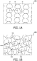
- the engineered surface of contacting portion 64A includes a number of surface features 70, wherein each surface feature 70 is a dome-shaped structure extending upwardly from a bottom surface 72 of contacting portion 64A.
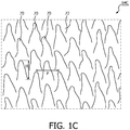
- the engineered surface of contacting portion 64B comprises a serrated configuration wherein the surface features include a number of ridges 74B and a number of pillar members 76B formed by the intersection of four adjacent ridges 74B.
- a valley 78B is formed in the area defined by each group of four immediately adjacent ridges 74B.
- the engineered surface of contacting portion 64C includes a number of surface features 70 wherein each surface feature 70 is a pillar structure extending upwardly from a bottom surface 72 of contacting portion 64C. Still further exemplary contacting portions 64G-64J comprising further exemplary engineered surfaces are shown in FIGS. 1G-1J .
- the engineered surface of contacting portion is characterized by two particular design parameters, namely the pitch (P) of the surface features and the height (H) of the surface features.
- the term “pitch” shall mean the distance between corresponding portions of immediately adjacent pairs of like surface features
- the term “height” shall mean the vertical distance between the highest point of a surface feature and the lowest surface 72 of contacting portion 64 on which the surface features sits.
- the pitch (P) and the height (H) of the dome-shaped surface features 70 of that embodiment are labeled P and H, respectively.
- pitch is measured between immediately adjacent pillar members 76B and height is measured from the top of each pillar member 76B (which are the tallest surface features) to the deepest point of the valleys 78B.
- pitch may be measured between the centers of immediately adjacent ridges 74B.
- the specific material may be silicone having a durometer of 40 Shore A. In another exemplary, non limiting embodiment, the specific material may be liquid silicone rubber having a durometer of 5 Shore A.
- the performance of contacting portion 64 may be optimized by employing an engineered surface wherein the pitch between each immediately adjacent pair of like surface features is less than or equal to some predetermined maximum pitch value (P max ) and the height of each like surface feature is less than or equal to some predetermined height value (H max ).
- the engineered surface is characterized by a pitch wherein the pitch is consistent and equal throughout the surface (as used herein, when comparing the pitch values of adjacent surface features within an engineered surface, "equal” shall mean the pitch values are all within a 10% or less manufacturing tolerance of one another) and is less than or equal to P max . Examples of such surfaces wherein the pitch is consistent and equal are shown in FIGS. 1A, 1B and FIG. 2 (described below).
- the engineered surface is characterized by a pitch wherein the pitch is anisotropic, meaning it has different dimensions/properties along different directions. More particularly, in this embodiment, the pitch will have a consistent and equal first pitch value P1 in a first direction and a consistent and equal second pitch value P2 in second direction transverse to (e.g., perpendicular to) the first direction.
- a consistent and equal first pitch value P1 in a first direction and a consistent and equal second pitch value P2 in second direction transverse to (e.g., perpendicular to) the first direction.
- FIG. ID using dome-shaped surface features 70.
- FIG. IE Another example of such an embodiment is shown in FIG. IE, wherein a serrated configuration as described elsewhere herein is employed.
- the engineered surface is characterized by a pitch wherein the pitch may vary throughout the surface but in each case is less than or equal to P max .
- P max An example of such an embodiment is shown in FIG. IF using dome-shaped surface features 70 (although features having other shapes may also be employed).
- Pi PI, P2, ... PN, wherein 0 ⁇ Pi ⁇ P max , or 2R ⁇ Pi ⁇ P max , where R is the radius of the hemispherically-shaped dome.
- each of the pitch values is within 50% of one another.
- the maximum variation of the pitch values is somewhere between 10% and 50% of one another (to avoid optical stitching and vibration noise effects).
- the engineered surface is characterized by a height wherein the height is consistent and equal throughout the surface (i.e., for each similar surface feature; as used herein, when comparing the height values of the surface features within an engineered surface, "equal" shall mean within a 30% or less manufacturing tolerance of one another) and is less than or equal to H max .
- P max is equal to 100 microns and H max is equal to 100 microns.
- pitch P and height H are characterized as follows: P ⁇ 100 microns and H ⁇ 100 microns.
- pitch P and height H are characterized as follows: P ⁇ 50 microns (or, alternatively P ⁇ 100 microns, or 20 microns ⁇ P ⁇ 50 microns) and 10 microns ⁇ H ⁇ 40 microns.
- pitch P and height H are characterized as follows: 20 microns ⁇ P ⁇ 50 microns (or, alternatively 10 microns ⁇ P ⁇ 50 microns, P ⁇ 50 microns, or P ⁇ 100 microns) and 10 microns ⁇ H ⁇ 20 microns.
- P max is greater than or equal to 10 microns and less than or equal to 100 microns
- H max is greater than or equal to 10 microns and less than or equal to 100 micron.
- an engineered surface according to these exemplary embodiments when implemented on a skin contacting surface such as contacting portion 64, will not have a negative effect on the user's skin during use and thus will optimize performance. For example, it has been determined that such configurations will not provide an undue stress concentration on the deeper layers of the user's skin.
- a maximum height H is specified.
- One reason that a maximum height H is specified is to limit the possibility that undue deflection/deformation of the tallest surface features (e.g., dome-shaped features 70 ( FIG. 1A ) and pillars 76 and 70 ( FIGS. 1B and 1C )) will occur when contacting surface 64 engages and applies a force to the skin of the user. Too much deflection of the tallest surface features will result in additional static friction during use, and thus is not desirable.
- the present inventors have determined that a deflection of 1 micron or less in response to a normal pressure of 4.4 kPa and a friction coefficient of 1 is desired in order to avoid undesirable static friction.
- the maximum height is specified so as to result in surface features that are stiff/rigid enough to have a deflection of 1 micron or less.
- the height of each of the surface features may be less than 20 microns, less than or equal to 15 microns, or less than or equal to 10 microns, each with a pitch (e.g., isotropic or anisotropic) of less than 50 microns (or, alternatively a pitch (isotropic or anisotropic) of less than 30 microns).
- an engineered surface (having anisotropic pitch) was created using a nanosecond laser wherein the surface features have a pitch of 50 microns and a height of 13 microns in a first direction and a pitch of 50 microns and a height of 5 microns in a second direction.
- the present inventors have determined that it is beneficial for the engineered surface of contacting portion 64 to prevent excessive "doming" of the user's skin (i.e., deformation of the skin toward the contacting surface 64 when it engages and applies a force to the skin) to an extent where the skin would touch the portions of the contacting surface 64 between the tallest surface features (e.g., bottom surface 72 ( FIGS. 1A and 1C ) and valleys 78B ( FIG. 1B )).
- Such excessive doming is undesirable because it results in additional skin contact area and thus additional friction and potential red mark formation.
- it is advantageous to specify a minimum height for the tallest surface features e.g., dome-shaped features 70 ( FIG.
- pitch P and height H are characterized as follows: 20 microns ⁇ P ⁇ 50 microns and 10 microns ⁇ H ⁇ 20 microns.
- FIG. 2 is a schematic representation of one particular, non-limiting embodiment of a contacting portion having an engineered surface employing the dome-shaped features 70.
- each dome-shaped feature 70 has an axi-symmetric profile as shown in FIG. 2 such that the dome-shaped feature 70 is symmetrical about a central axis 80 of the dome-shaped feature 70.
- each dome-shaped feature 70 includes a hemispherically-shaped tip portion 82 having a radius R that is connected to a frusto-conically-shaped bottom portion 84 (i.e., bottom portion 84 has the shape of a frustum, which as used herein shall mean a cone whose tip has been truncated by a plane parallel to its base) having a half top angle ⁇ measured with respect to central axis 80.
- tip portion 82 has a radius R that is between 5 and 10 microns.
- Bottom portion 84 has a half top angle ⁇ that is equal to 10-60 degrees depending on the material durometer (in one specific implementation it is equal to 30 degrees for a material durometer of 40 Shore A).
- the pitch P and height H of exemplary contacting portion 64 shown in FIG. 2 are characterized as follows: 20 microns ⁇ P ⁇ 50 microns and 10 microns ⁇ H ⁇ 20 microns.
- contacting portion 64 having an engineered surface as described herein is formed using a molding process, wherein the mold is formed so as to impart the engineered surface onto the molded product.
- a suitable mold may be constructed by forming the mold surfaces using a laser technology (e.g., a femto-laser, a pico-laser or a nano-laser). Once the mold is formed, the laser engineered mold surface is transferred to the surface, thus giving the surface its texture.
- a suitable mold may also be employed to create a suitable mold, such as, without limitation, milling, polishing, sand blasting, etching or electric discharge machining.
- an engineered surface that contact the user's skin may be made of a soft, flexible, cushiony, elastomeric material, such as, without limitation, silicone, an appropriately soft thermoplastic elastomer (such as thermoplastic polyurethanes (TPU)), latex, polybutadiene, a closed cell foam, or any combination of such materials.
- a soft, flexible, cushiony, elastomeric material such as, without limitation, silicone, an appropriately soft thermoplastic elastomer (such as thermoplastic polyurethanes (TPU)), latex, polybutadiene, a closed cell foam, or any combination of such materials.
- such materials may be any rubbery or elastomeric polymer material, e.g., one wherein an organic monomer is selected from the group consisting of butadiene, isoprene, dialkylsiloxanes, diarylsiloxanes, acrylic acid alkyl esters, acrylonitrile, chloroprene, fluorinated ethylene, mixtures of ethylene and vinyl acetate, mixtures of ethylene and one or more acrylic acid esters, and mixtures of ethylene with propylene and a diene.
- an organic monomer is selected from the group consisting of butadiene, isoprene, dialkylsiloxanes, diarylsiloxanes, acrylic acid alkyl esters, acrylonitrile, chloroprene, fluorinated ethylene, mixtures of ethylene and vinyl acetate, mixtures of ethylene and one or more acrylic acid esters, and mixtures of ethylene with propylene and a diene.
- an organic monomer is selected
- any of the materials listed above with the following softness and/or elasticity characteristics may be used to make the elements including an engineered surface described herein: durometer of 2-55 Shore A and elastic modulus of 0.1-3.5 MPa (or 0.1-1.5 MPa), or, alternatively, durometer of 2-50 Shore A and elastic modulus of 0.1-3.5 MPa (or 0.1-1.5 MPa), or, still alternatively, durometer of 5-50 Shore A and elastic modulus of 0.1 -3.5 MPa (or 0.1-1.5 MPa).
- silicone having durometer of 2 Shore A and an elastic modulus of 0.15 MPa silicone having durometer of 2 Shore A and an elastic modulus of 0.15 MPa
- silicone having durometer of 5 Shore A and an elastic modulus of 0.3 MPa silicone having durometer of 40 Shore A and an elastic modulus of 1.4 MPa.
- an engineered surface provides for a certain degree of self cleaning.
- the engineered surfaces as described herein hold less skin cells than a prior art flat reference surface. Because skin organic material that adheres to a skin-contacting surface is a source of bacterial growth, and because such bacterial growth can stimulate skin redness, a configuration that can reduce the number of adhering skin cells will be advantageous.
- an engineered surface as described herein may, for example, form part of an in-lay or patch (e.g., disposable)Engineered surfaces as described herein may be used on contacting portions of different types of devices, such as, without limitation, It is also to be understood that the use of the engineered surfaces as described herein are not limited to any specific device . Instead, the engineered surfaces can be used to form tissue contacting portions on a wide variety of devices. For example, as seen in FIG.
- FIG. 3 which is a schematic diagram of one embodiment of a set of earphones 100 having earpieces 102 formed from a soft, flexible elastomeric material, such as, without limitation, silicone, the engineered surfaces as described herein in the various embodiments can be used to form skin contacting portions 104 on earpieces 102.
- FIG. 4 which is a schematic diagram of another embodiment of a set of earphones 106 having earpieces 108 formed from a soft, flexible elastomeric material, such as, without limitation, silicone, the engineered surfaces as described herein in the various embodiments can be used to form skin contacting portions 110 on earpieces 108.
- FIG. 4 which is a schematic diagram of another embodiment of a set of earphones 106 having earpieces 108 formed from a soft, flexible elastomeric material, such as, without limitation, silicone
- the engineered surfaces as described herein in the various embodiments can be used to form skin contacting portions 110 on earpieces 108.
- FIG. 5 is a schematic diagram of one embodiment of a baby bottle 112 having a nipple or teat 114 formed from a soft, flexible elastomeric material, such as, without limitation, silicone, the engineered surfaces as described herein in the various embodiments can be used to form a tissue contacting portion 116 on nipple or teat 114.
- a soft, flexible elastomeric material such as, without limitation, silicone
- FIG. 6 which is a schematic diagram of one embodiment of a breast pump 118 having a receptacle 120, a handle driven pump assembly 122, and a breast flange 124 formed from a soft, flexible elastomeric material, such as, without limitation, silicone, the engineered surfaces as described herein in the various embodiments can be used to form a tissue contacting portion 126 of breast flange 124.
- FIG. 7 which is a rear schematic diagram of one embodiment of a wrist watch 128 having heart rate monitoring functionality. As seen in FIG. 7 , watch 128 includes a central portion 130 and straps 132A and 132B.
- Central portion 130 includes a sensor area 134 structured to hold a sensor and a tissue contacting portion 136 surrounding the sensor area 134.
- the tissue contacting portion 136 includes an engineered surface as described herein in the various embodiments. The main function of the engineered surface is to prevent slip between the sensor provided in sensor area 134 and the skin while at the same time providing skin comfort.
- tissue contacting portion 136 comprises a silicone rubber patch attached to the back side of watch 128.
- the sensor application as just described is not limited to wrist watches, but instead can be any type of sensor application to the skin.
- the contacting portions 104, 110, 116, 126, 136 can, alternatively, be provided over only a portion of the earpieces 102, the earpieces 108, the nipple or teat 114, the breast flange 124, or the watch 128 as the case may be, in a select pattern or select locations.
- FIG. 2 is a schematic representation of one particular, non-limiting embodiment of contacting portion 64A having an engineered surface employing dome-shaped features 70 wherein each dome-shaped feature 70 has an axi-symmetric profile and is symmetrical about a central axis 80 of the dome-shaped feature 70.
- each dome-shaped feature 70 includes a hemispherically-shaped tip portion 82 having a radius R that is connected to a frusto-conically-shaped bottom portion 84.
- FIG. 8 is a cross-sectional view of a specific, non-limiting implementation of contacting portion 64A of FIG. 2 , labeled 64A-1.
- the engineered surface has the following parameters/characteristics: (i) contacting portion 64A-1 is made of a material, such as silicone, having a durometer of 5 Shore A and an elastic modulus of 0.1-1.5 MPa (e.g.
- each dome-shaped feature 70-1 has a base radius (BR) equal to 7.5 microns, (iii) the pitch P of dome-shaped features 70-1 in contacting portion 64A-1 is 15 microns, (iv) the height of each dome-shaped feature 70-1 is 10 microns, and (v) the dome-shaped features 70-1 in contacting portion 64A-1 have a deflection of 1 micron or less (e.g., 0.869926 microns or less) in response to a normal pressure of 0.01 MPa and a friction coefficient of 1.
- BR base radius
- the pitch P of dome-shaped features 70-1 in contacting portion 64A-1 is 15 microns
- the height of each dome-shaped feature 70-1 is 10 microns
- the dome-shaped features 70-1 in contacting portion 64A-1 have a deflection of 1 micron or less (e.g., 0.869926 microns or less) in response to a normal pressure of 0.01 MPa and a friction coefficient of 1.
- FIG. 9 is a cross-sectional view of another specific, non-limiting implementation of contacting portion 64A of FIG. 2 , labeled 64A-2.
- the engineered surface has the following parameters/characteristics: (i) contacting portion 64A-2 is made of a material, such as silicone, having a durometer of 5 Shore A and an elastic modulus of 0.1-1.5 MPa (e.g.
- each dome-shaped feature 70-2 has a base radius (BR) equal to 7.5 microns
- the pitch P of dome-shaped features 70-2 in contacting portion 64A-2 is 30 microns
- the height of each dome-shaped feature 70-2 is 5 microns
- the dome-shaped features 70-2 in contacting portion 64A-2 have a deflection of 0.5 microns or less (e.g, 0.434963 microns or less) in response to a normal pressure of 0.01 MPa and a friction coefficient of 1.
- FIG. 10 is a cross-sectional view of yet another specific, non-limiting implementation of contacting portion 64A of FIG. 2 , labeled 64A-3.
- the engineered surface has the following parameters/characteristics: (i) contacting portion 64A-3 is made of a material, such as silicone, having a durometer of 5 Shore A and an elastic modulus of 0.1-1.5 MPa (e.g.
- each dome-shaped feature 70-3 has a base radius (BR) equal to 5 microns
- the pitch P of dome-shaped features 70-3 in contacting portion 64A-3 is 15 microns
- the height of each dome-shaped feature 70-3 is 5 microns
- the dome-shaped features 70-3 in contacting portion 64A-3 have a deflection of 0.6 microns o rless (e.g., 0.5505 microns or less) in response to a normal pressure of 0.01 MPa and a friction coefficient of 1.
- FIG. 11 is a cross-sectional view of still another specific, non-limiting implementation of contacting portion 64A of FIG. 2 , labeled 64A-4.
- the engineered surface has the following parameters/characteristics: (i) contacting portion 64A-4 is made of a material, such as silicone, having a durometer of 5 Shore A and an elastic modulus of 0.1-1.5 MPa (e.g.
- each dome-shaped feature 70-4 has a base radius (BR) equal to 5 microns
- the pitch P of dome-shaped features 70-4 in contacting portion 64A-4 is 10 microns
- the height of each dome-shaped feature 70-4 is 5 microns
- the dome-shaped features 70-4 in contacting portion 64A-4 have a deflection of 0.3 microns o rless (e.g., 0.244667 microns or less) in response to a normal pressure of 0.01 MPa and a friction coefficient of 1.
- any reference signs placed between parentheses shall not be construed as limiting the claim.
- the word “comprising” or “including” does not exclude the presence of elements or steps other than those listed in a claim.
- several of these means may be embodied by one and the same item of hardware.
- the word “a” or “an” preceding an element does not exclude the presence of a plurality of such elements.
- any device claim enumerating several means several of these means may be embodied by one and the same item of hardware.
- the mere fact that certain elements are recited in mutually different dependent claims does not indicate that these elements cannot be used in combination.
Landscapes
- Health & Medical Sciences (AREA)
- Life Sciences & Earth Sciences (AREA)
- Engineering & Computer Science (AREA)
- Animal Behavior & Ethology (AREA)
- General Health & Medical Sciences (AREA)
- Public Health (AREA)
- Veterinary Medicine (AREA)
- Physics & Mathematics (AREA)
- Heart & Thoracic Surgery (AREA)
- Biomedical Technology (AREA)
- Medical Informatics (AREA)
- Pathology (AREA)
- Biophysics (AREA)
- Signal Processing (AREA)
- Acoustics & Sound (AREA)
- Molecular Biology (AREA)
- Surgery (AREA)
- Materials For Medical Uses (AREA)
- External Artificial Organs (AREA)
- Medical Preparation Storing Or Oral Administration Devices (AREA)
- Headphones And Earphones (AREA)
- Prostheses (AREA)
- Professional, Industrial, Or Sporting Protective Garments (AREA)
- Massaging Devices (AREA)
- Pediatric Medicine (AREA)
- Vascular Medicine (AREA)
- Anesthesiology (AREA)
- Hematology (AREA)
- Orthopedics, Nursing, And Contraception (AREA)
- Floor Finish (AREA)
Claims (10)
- Appareil (30, 90, 100, 106, 112, 118) structuré pour entrer en contact avec la surface externe d'un tissu externe d'un utilisateur pendant son utilisation, comprenant:- une partie de contact (64, 94, 104, 110, 116, 124) structurée pour engager directement le tissu externe, où au moins une section de la partie de contact a une surface ouvragée comprenant une pluralité de caractéristiques de surface prédéfinies non aléatoires (70, 76) ayant chacune une géométrie similaire, où dans la section un pas entre chaque paire immédiatement adjacente des caractéristiques de surface est inférieur ou égal à une valeur de pas maximale prédéterminée, et où dans la section une hauteur de chacune des caractéristiques de surface est inférieure ou égale à une valeur de hauteur maximale prédéterminée, ladite valeur de pas maximale prédéterminée étant de 100 microns, ladite valeur de hauteur maximale prédéterminée étant de 100 microns, où chacune des caractéristiques de surface (70, 76) a un profil en forme de dôme axisymétrique, oùchacune des caractéristiques de surface (70, 76) a une partie de pointe (82) couplée à une partie de base (84), caractérisé en ce que
la partie de pointe a un rayon compris entre 5 et 10 microns, et où
la partie de base est de forme tronconique et a un demi-angle (θ) mesuré par rapport à un axe central (80) de la partie de base compris entre 10 et 60 degrés. - Appareil selon la revendication 1, dans lequel dans la section les hauteurs de chacune des caractéristiques de surface sont égales entre elles.
- Appareil selon la revendication 1, dans lequel la valeur de pas maximale prédéterminée est l'une quelconque de: (i) 50 microns, ou (ii) supérieure ou égale à 10 microns et inférieure ou égale à 100 microns, ou dans lequel le pas entre chaque paire immédiatement adjacente des caractéristiques de surface est l'un quelconque de: (i) supérieur ou égal à 10 microns et inférieur ou égal à 50 microns, ou (ii) supérieur ou égal à 20 microns et inférieur ou égal à 50 microns.
- Appareil selon la revendication 3, dans lequel la valeur de hauteur maximale prédéterminée est l'une quelconque de: (i) 40 microns, (ii) 20 microns, ou (iii) supérieure ou égale à 10 microns et inférieure ou égale à 100 microns, ou dans lequel la hauteur de chacune des caractéristiques de surface est l'une quelconque de: (i) supérieure ou égale à 10 microns et inférieure ou égale à 40 microns, ou (ii) supérieure ou égale à 10 microns et inférieure ou égale à 20 microns.
- Appareil selon la revendication 1, dans lequel l'appareil est choisi dans le groupe comprenant: (i) un tire-lait (118), où la partie de contact (64) fait partie d'une flasque pour le sein (124), (ii) un ensemble de écouteurs (100, 106), où la partie de contact (104, 110) fait partie d'un écouteur (102, 108), (iii) un biberon (112), où la partie de contact (116) fait partie de une tétine (114), (iv) un dispositif capteur (128), où la partie de contact est prévue sur une surface en contact avec la peau du dispositif capteur.
- Appareil selon la revendication 1, dans lequel une déflexion de chacune des caractéristiques de surface est égale à 1 micron ou inférieure en réponse à une pression normale de 4,4 kPa.
- Appareil selon la revendication 1, dans lequel dans la section le pas entre chaque paire immédiatement adjacente des caractéristiques de surface est de 10 à 30 microns, où chacune des caractéristiques de surface a une partie de base (84) ayant un rayon de 5 à 7,5 microns, où dans la section la hauteur de chacune des caractéristiques de surface est inférieure ou égale à 10 microns, et où une déflexion de chacune des caractéristiques de surface est égale à 1 micron ou inférieure en réponse à une pression normale de 0,01 MPa.
- Appareil selon la revendication 7, dans lequel la partie de contact est constituée d'un matériau ayant un duromètre de 5 Shore A et un module élastique de 0,1 à 1,5 MPa.
- Appareil selon la revendication 1, dans lequel au moins une section de la partie de contact est constituée d'un matériau ayant un duromètre de 2 à 55 Shore A et un module élastique de 0,1 à 3,5 MPa.
- Procédé de réalisation d'un appareil (30, 90, 100, 106, 112, 118) structuré pour entrer en contact avec la surface externe d'un tissu externe d'un utilisateur pendant son utilisation, comprenant:- la conception d'une surface ouvragée où au moins une section de la surface ouvragée comprend une pluralité de caractéristiques de surface prédéfinies non aléatoires (70, 76) ayant chacune une géométrie similaire, où dans la section un pas entre chaque paire immédiatement adjacente des caractéristiques de surface est inférieur ou égal à une valeur de pas maximale prédéterminée, et où dans la section les hauteurs de chacune des caractéristiques de surface sont égales entre elles et inférieures ou égales à une valeur de hauteur maximale prédéterminée, ladite valeur de pas maximale prédéterminée étant de 100 microns, ladite valeur de hauteur maximale prédéterminée étant de 100 microns; et- la formation d'une partie de contact (64, 94, 104, 110, 116, 126) pour l'appareil d'une manière dans laquelle la partie de contact comprend la surface ouvragée, la partie de contact étant structurée pour engager directement le tissu externe de l'utilisateur, où chacune des caractéristiques de surface (70, 76) a un profil en forme de dôme axisymétrique, oùchacune des caractéristiques de surface (70, 76) a une partie de pointe (82) couplée à une partie de base (84) caractérisée en ce que
la partie de pointe a un rayon compris entre 5 et 10 microns, et où
la partie de base est de forme tronconique et a un demi-angle (θ) mesuré par rapport à un axe central (80) de la partie de base compris entre 10 et 60 degrés.
Applications Claiming Priority (2)
| Application Number | Priority Date | Filing Date | Title |
|---|---|---|---|
| US201261586865P | 2012-01-16 | 2012-01-16 | |
| PCT/IB2013/050190 WO2013108154A1 (fr) | 2012-01-16 | 2013-01-09 | Surface ouvragée permettant d'obtenir un faible frottement et un confort amélioré sur des dispositifs en contact avec la peau ou un autre tissu externe de l'utilisateur |
Publications (2)
| Publication Number | Publication Date |
|---|---|
| EP2804733A1 EP2804733A1 (fr) | 2014-11-26 |
| EP2804733B1 true EP2804733B1 (fr) | 2020-07-08 |
Family
ID=47790273
Family Applications (1)
| Application Number | Title | Priority Date | Filing Date |
|---|---|---|---|
| EP13707435.7A Active EP2804733B1 (fr) | 2012-01-16 | 2013-01-09 | Surface ouvragée permettant d'obtenir un faible frottement et un confort amélioré sur des dispositifs en contact avec la peau ou un autre tissu externe de l'utilisateur |
Country Status (7)
| Country | Link |
|---|---|
| US (1) | US9840109B2 (fr) |
| EP (1) | EP2804733B1 (fr) |
| JP (1) | JP6491479B2 (fr) |
| CN (1) | CN104053531B (fr) |
| BR (1) | BR112014017142A8 (fr) |
| RU (1) | RU2627381C2 (fr) |
| WO (1) | WO2013108154A1 (fr) |
Families Citing this family (8)
| Publication number | Priority date | Publication date | Assignee | Title |
|---|---|---|---|---|
| USD773194S1 (en) * | 2015-02-06 | 2016-12-06 | Nice-Pak Products, Inc. | Nonwoven fabric with surface pattern |
| US11097436B2 (en) * | 2016-06-20 | 2021-08-24 | Koninklijke Philips N.V. | Friction control device and method |
| US9913780B2 (en) * | 2016-07-21 | 2018-03-13 | Carr Lane Quackenbush | Bite-safe artificial teat |
| US10531174B2 (en) * | 2016-10-13 | 2020-01-07 | Bose Corporation | Earpiece employing cooling and sensation inducing materials |
| US10602250B2 (en) | 2016-10-13 | 2020-03-24 | Bose Corporation | Acoustaical devices employing phase change materials |
| US10623846B2 (en) * | 2016-12-06 | 2020-04-14 | Bose Corporation | Earpieces employing viscoelastic materials |
| EP3619919B1 (fr) | 2017-05-03 | 2022-01-12 | Bose Corporation | Dispositif portable à adhesion améliorée |
| EP3829517A4 (fr) * | 2018-08-01 | 2022-05-04 | Lactamo Holdings Pty Ltd | Aide à la lactation et dispositif thérapeutique de tissu mammaire |
Citations (3)
| Publication number | Priority date | Publication date | Assignee | Title |
|---|---|---|---|---|
| WO2009093173A1 (fr) * | 2008-01-25 | 2009-07-30 | Koninklijke Philips Electronics N.V. | Tétine |
| WO2011048988A1 (fr) * | 2009-10-20 | 2011-04-28 | 日産自動車株式会社 | Structure de surface pour un article |
| WO2011138735A1 (fr) * | 2010-05-04 | 2011-11-10 | Koninklijke Philips Electronics N.V. | Dispositif actionneur à caractéristiques tactiles améliorées |
Family Cites Families (17)
| Publication number | Priority date | Publication date | Assignee | Title |
|---|---|---|---|---|
| US5753343A (en) | 1992-08-04 | 1998-05-19 | Minnesota Mining And Manufacturing Company | Corrugated nonwoven webs of polymeric microfiber |
| AU3328799A (en) | 1998-03-06 | 1999-09-20 | Ameda Ag Medical Equipment | Breast pump |
| US6372323B1 (en) * | 1998-10-05 | 2002-04-16 | 3M Innovative Properties Company | Slip control article for wet and dry applications |
| US6312612B1 (en) * | 1999-06-09 | 2001-11-06 | The Procter & Gamble Company | Apparatus and method for manufacturing an intracutaneous microneedle array |
| US6729332B1 (en) | 1999-10-22 | 2004-05-04 | 3M Innovative Properties Company | Retention assembly with compression element and method of use |
| US7522743B2 (en) | 2002-01-07 | 2009-04-21 | Step Communications | High comfort sound delivery system |
| DE10227787B4 (de) * | 2002-03-22 | 2006-02-23 | Novatex Gmbh | Sauger |
| US20090107515A1 (en) | 2003-06-10 | 2009-04-30 | Oren Gavriely | Protective mask |
| US7640933B1 (en) | 2004-02-13 | 2010-01-05 | RIC Investment, Inc. | Hybrid textured/polished respiratory mask seal and respiratory mask using same |
| EP1652545A1 (fr) * | 2004-10-29 | 2006-05-03 | Universität Duisburg-Essen | Surface pour contact avec un tissu humain, animal ou artificiel |
| US7833203B2 (en) * | 2005-03-31 | 2010-11-16 | Cordis Neurovascular, Inc. | Catheter shaft with undulating surface for reduced friction |
| WO2008070929A1 (fr) | 2006-12-15 | 2008-06-19 | Resmed Ltd | Administration d'inhalotherapie |
| WO2009026627A1 (fr) | 2007-08-31 | 2009-03-05 | Resmed Ltd | Masque respiratoire pourvu d'elements textiles |
| EP2219719B1 (fr) | 2007-11-15 | 2017-12-27 | ResMed Limited | Structure de rembourrage |
| WO2010028425A1 (fr) | 2008-09-12 | 2010-03-18 | Resmed Ltd | Procédé et appareil pour structure d'interface à base de mousse |
| NZ740593A (en) * | 2009-06-02 | 2019-10-25 | ResMed Pty Ltd | Unobtrusive nasal mask |
| EP2281595B1 (fr) * | 2009-07-29 | 2013-06-26 | ResMed R&D Germany GmbH | Structure de surface sur une interface de patient |
-
2013
- 2013-01-09 US US14/370,987 patent/US9840109B2/en active Active
- 2013-01-09 BR BR112014017142A patent/BR112014017142A8/pt active Search and Examination
- 2013-01-09 JP JP2014551708A patent/JP6491479B2/ja active Active
- 2013-01-09 WO PCT/IB2013/050190 patent/WO2013108154A1/fr not_active Ceased
- 2013-01-09 EP EP13707435.7A patent/EP2804733B1/fr active Active
- 2013-01-09 RU RU2014133737A patent/RU2627381C2/ru active
- 2013-01-09 CN CN201380005613.8A patent/CN104053531B/zh active Active
Patent Citations (4)
| Publication number | Priority date | Publication date | Assignee | Title |
|---|---|---|---|---|
| WO2009093173A1 (fr) * | 2008-01-25 | 2009-07-30 | Koninklijke Philips Electronics N.V. | Tétine |
| WO2011048988A1 (fr) * | 2009-10-20 | 2011-04-28 | 日産自動車株式会社 | Structure de surface pour un article |
| EP2492075A1 (fr) * | 2009-10-20 | 2012-08-29 | Nissan Motor Co., Ltd. | Structure de surface pour un article |
| WO2011138735A1 (fr) * | 2010-05-04 | 2011-11-10 | Koninklijke Philips Electronics N.V. | Dispositif actionneur à caractéristiques tactiles améliorées |
Also Published As
| Publication number | Publication date |
|---|---|
| JP2015509014A (ja) | 2015-03-26 |
| WO2013108154A1 (fr) | 2013-07-25 |
| US9840109B2 (en) | 2017-12-12 |
| RU2627381C2 (ru) | 2017-08-08 |
| CN104053531B (zh) | 2017-05-03 |
| US20140349075A1 (en) | 2014-11-27 |
| BR112014017142A8 (pt) | 2021-02-17 |
| BR112014017142A2 (pt) | 2017-06-13 |
| JP6491479B2 (ja) | 2019-03-27 |
| RU2014133737A (ru) | 2016-03-20 |
| CN104053531A (zh) | 2014-09-17 |
| EP2804733A1 (fr) | 2014-11-26 |
Similar Documents
| Publication | Publication Date | Title |
|---|---|---|
| US9840109B2 (en) | Engineered surface for providing low friction and improved comfort on devices that contact the skin or other external tissue of the user | |
| EP2804653B1 (fr) | Dispositif d'interface patient ayant une surface élaborée pour assurer un frottement faible et un confort amélioré à l'utilisateur | |
| US12070552B2 (en) | Foam-based interfacing structure | |
| EP3228214B1 (fr) | Coussin d'assise à structure en nid d'abeille | |
| US11058570B2 (en) | Device and method for opening an airway | |
| JP2019524336A (ja) | マッサージデバイス | |
| TW201208739A (en) | Goggle mask, check valve device thereof and method for manufacturing said check valve device thereof | |
| US20190009458A1 (en) | Surface feature arrays for additively manufactured products | |
| WO2019028330A1 (fr) | Dispositif et procédé d'ouverture de voies respiratoires | |
| CN214387113U (zh) | 一种具有防滑效果的硅胶垫 | |
| CN102380188A (zh) | 防水面罩 | |
| NZ754381B2 (en) | A foam-based interfacing structure method and apparatus |
Legal Events
| Date | Code | Title | Description |
|---|---|---|---|
| PUAI | Public reference made under article 153(3) epc to a published international application that has entered the european phase |
Free format text: ORIGINAL CODE: 0009012 |
|
| 17P | Request for examination filed |
Effective date: 20140818 |
|
| AK | Designated contracting states |
Kind code of ref document: A1 Designated state(s): AL AT BE BG CH CY CZ DE DK EE ES FI FR GB GR HR HU IE IS IT LI LT LU LV MC MK MT NL NO PL PT RO RS SE SI SK SM TR |
|
| DAX | Request for extension of the european patent (deleted) | ||
| STAA | Information on the status of an ep patent application or granted ep patent |
Free format text: STATUS: EXAMINATION IS IN PROGRESS |
|
| 17Q | First examination report despatched |
Effective date: 20180329 |
|
| GRAP | Despatch of communication of intention to grant a patent |
Free format text: ORIGINAL CODE: EPIDOSNIGR1 |
|
| STAA | Information on the status of an ep patent application or granted ep patent |
Free format text: STATUS: GRANT OF PATENT IS INTENDED |
|
| INTG | Intention to grant announced |
Effective date: 20200207 |
|
| RAP1 | Party data changed (applicant data changed or rights of an application transferred) |
Owner name: KONINKLIJKE PHILIPS N.V. |
|
| GRAS | Grant fee paid |
Free format text: ORIGINAL CODE: EPIDOSNIGR3 |
|
| GRAA | (expected) grant |
Free format text: ORIGINAL CODE: 0009210 |
|
| STAA | Information on the status of an ep patent application or granted ep patent |
Free format text: STATUS: THE PATENT HAS BEEN GRANTED |
|
| AK | Designated contracting states |
Kind code of ref document: B1 Designated state(s): AL AT BE BG CH CY CZ DE DK EE ES FI FR GB GR HR HU IE IS IT LI LT LU LV MC MK MT NL NO PL PT RO RS SE SI SK SM TR |
|
| REG | Reference to a national code |
Ref country code: GB Ref legal event code: FG4D |
|
| REG | Reference to a national code |
Ref country code: AT Ref legal event code: REF Ref document number: 1287970 Country of ref document: AT Kind code of ref document: T Effective date: 20200715 Ref country code: CH Ref legal event code: EP |
|
| REG | Reference to a national code |
Ref country code: DE Ref legal event code: R096 Ref document number: 602013070477 Country of ref document: DE |
|
| REG | Reference to a national code |
Ref country code: IE Ref legal event code: FG4D |
|
| REG | Reference to a national code |
Ref country code: LT Ref legal event code: MG4D |
|
| REG | Reference to a national code |
Ref country code: AT Ref legal event code: MK05 Ref document number: 1287970 Country of ref document: AT Kind code of ref document: T Effective date: 20200708 |
|
| REG | Reference to a national code |
Ref country code: NL Ref legal event code: MP Effective date: 20200708 |
|
| PG25 | Lapsed in a contracting state [announced via postgrant information from national office to epo] |
Ref country code: AT Free format text: LAPSE BECAUSE OF FAILURE TO SUBMIT A TRANSLATION OF THE DESCRIPTION OR TO PAY THE FEE WITHIN THE PRESCRIBED TIME-LIMIT Effective date: 20200708 Ref country code: BG Free format text: LAPSE BECAUSE OF FAILURE TO SUBMIT A TRANSLATION OF THE DESCRIPTION OR TO PAY THE FEE WITHIN THE PRESCRIBED TIME-LIMIT Effective date: 20201008 Ref country code: GR Free format text: LAPSE BECAUSE OF FAILURE TO SUBMIT A TRANSLATION OF THE DESCRIPTION OR TO PAY THE FEE WITHIN THE PRESCRIBED TIME-LIMIT Effective date: 20201009 Ref country code: NO Free format text: LAPSE BECAUSE OF FAILURE TO SUBMIT A TRANSLATION OF THE DESCRIPTION OR TO PAY THE FEE WITHIN THE PRESCRIBED TIME-LIMIT Effective date: 20201008 Ref country code: FI Free format text: LAPSE BECAUSE OF FAILURE TO SUBMIT A TRANSLATION OF THE DESCRIPTION OR TO PAY THE FEE WITHIN THE PRESCRIBED TIME-LIMIT Effective date: 20200708 Ref country code: PT Free format text: LAPSE BECAUSE OF FAILURE TO SUBMIT A TRANSLATION OF THE DESCRIPTION OR TO PAY THE FEE WITHIN THE PRESCRIBED TIME-LIMIT Effective date: 20201109 Ref country code: LT Free format text: LAPSE BECAUSE OF FAILURE TO SUBMIT A TRANSLATION OF THE DESCRIPTION OR TO PAY THE FEE WITHIN THE PRESCRIBED TIME-LIMIT Effective date: 20200708 Ref country code: HR Free format text: LAPSE BECAUSE OF FAILURE TO SUBMIT A TRANSLATION OF THE DESCRIPTION OR TO PAY THE FEE WITHIN THE PRESCRIBED TIME-LIMIT Effective date: 20200708 Ref country code: SE Free format text: LAPSE BECAUSE OF FAILURE TO SUBMIT A TRANSLATION OF THE DESCRIPTION OR TO PAY THE FEE WITHIN THE PRESCRIBED TIME-LIMIT Effective date: 20200708 Ref country code: ES Free format text: LAPSE BECAUSE OF FAILURE TO SUBMIT A TRANSLATION OF THE DESCRIPTION OR TO PAY THE FEE WITHIN THE PRESCRIBED TIME-LIMIT Effective date: 20200708 |
|
| PG25 | Lapsed in a contracting state [announced via postgrant information from national office to epo] |
Ref country code: IS Free format text: LAPSE BECAUSE OF FAILURE TO SUBMIT A TRANSLATION OF THE DESCRIPTION OR TO PAY THE FEE WITHIN THE PRESCRIBED TIME-LIMIT Effective date: 20201108 Ref country code: LV Free format text: LAPSE BECAUSE OF FAILURE TO SUBMIT A TRANSLATION OF THE DESCRIPTION OR TO PAY THE FEE WITHIN THE PRESCRIBED TIME-LIMIT Effective date: 20200708 Ref country code: PL Free format text: LAPSE BECAUSE OF FAILURE TO SUBMIT A TRANSLATION OF THE DESCRIPTION OR TO PAY THE FEE WITHIN THE PRESCRIBED TIME-LIMIT Effective date: 20200708 Ref country code: RS Free format text: LAPSE BECAUSE OF FAILURE TO SUBMIT A TRANSLATION OF THE DESCRIPTION OR TO PAY THE FEE WITHIN THE PRESCRIBED TIME-LIMIT Effective date: 20200708 |
|
| PG25 | Lapsed in a contracting state [announced via postgrant information from national office to epo] |
Ref country code: NL Free format text: LAPSE BECAUSE OF FAILURE TO SUBMIT A TRANSLATION OF THE DESCRIPTION OR TO PAY THE FEE WITHIN THE PRESCRIBED TIME-LIMIT Effective date: 20200708 |
|
| REG | Reference to a national code |
Ref country code: DE Ref legal event code: R097 Ref document number: 602013070477 Country of ref document: DE |
|
| PG25 | Lapsed in a contracting state [announced via postgrant information from national office to epo] |
Ref country code: SM Free format text: LAPSE BECAUSE OF FAILURE TO SUBMIT A TRANSLATION OF THE DESCRIPTION OR TO PAY THE FEE WITHIN THE PRESCRIBED TIME-LIMIT Effective date: 20200708 Ref country code: RO Free format text: LAPSE BECAUSE OF FAILURE TO SUBMIT A TRANSLATION OF THE DESCRIPTION OR TO PAY THE FEE WITHIN THE PRESCRIBED TIME-LIMIT Effective date: 20200708 Ref country code: DK Free format text: LAPSE BECAUSE OF FAILURE TO SUBMIT A TRANSLATION OF THE DESCRIPTION OR TO PAY THE FEE WITHIN THE PRESCRIBED TIME-LIMIT Effective date: 20200708 Ref country code: CZ Free format text: LAPSE BECAUSE OF FAILURE TO SUBMIT A TRANSLATION OF THE DESCRIPTION OR TO PAY THE FEE WITHIN THE PRESCRIBED TIME-LIMIT Effective date: 20200708 Ref country code: EE Free format text: LAPSE BECAUSE OF FAILURE TO SUBMIT A TRANSLATION OF THE DESCRIPTION OR TO PAY THE FEE WITHIN THE PRESCRIBED TIME-LIMIT Effective date: 20200708 Ref country code: IT Free format text: LAPSE BECAUSE OF FAILURE TO SUBMIT A TRANSLATION OF THE DESCRIPTION OR TO PAY THE FEE WITHIN THE PRESCRIBED TIME-LIMIT Effective date: 20200708 |
|
| PLBE | No opposition filed within time limit |
Free format text: ORIGINAL CODE: 0009261 |
|
| STAA | Information on the status of an ep patent application or granted ep patent |
Free format text: STATUS: NO OPPOSITION FILED WITHIN TIME LIMIT |
|
| PG25 | Lapsed in a contracting state [announced via postgrant information from national office to epo] |
Ref country code: AL Free format text: LAPSE BECAUSE OF FAILURE TO SUBMIT A TRANSLATION OF THE DESCRIPTION OR TO PAY THE FEE WITHIN THE PRESCRIBED TIME-LIMIT Effective date: 20200708 |
|
| 26N | No opposition filed |
Effective date: 20210409 |
|
| PG25 | Lapsed in a contracting state [announced via postgrant information from national office to epo] |
Ref country code: SK Free format text: LAPSE BECAUSE OF FAILURE TO SUBMIT A TRANSLATION OF THE DESCRIPTION OR TO PAY THE FEE WITHIN THE PRESCRIBED TIME-LIMIT Effective date: 20200708 |
|
| PG25 | Lapsed in a contracting state [announced via postgrant information from national office to epo] |
Ref country code: SI Free format text: LAPSE BECAUSE OF FAILURE TO SUBMIT A TRANSLATION OF THE DESCRIPTION OR TO PAY THE FEE WITHIN THE PRESCRIBED TIME-LIMIT Effective date: 20200708 Ref country code: MC Free format text: LAPSE BECAUSE OF FAILURE TO SUBMIT A TRANSLATION OF THE DESCRIPTION OR TO PAY THE FEE WITHIN THE PRESCRIBED TIME-LIMIT Effective date: 20200708 |
|
| REG | Reference to a national code |
Ref country code: CH Ref legal event code: PL |
|
| GBPC | Gb: european patent ceased through non-payment of renewal fee |
Effective date: 20210109 |
|
| PG25 | Lapsed in a contracting state [announced via postgrant information from national office to epo] |
Ref country code: LU Free format text: LAPSE BECAUSE OF NON-PAYMENT OF DUE FEES Effective date: 20210109 |
|
| REG | Reference to a national code |
Ref country code: BE Ref legal event code: MM Effective date: 20210131 |
|
| PG25 | Lapsed in a contracting state [announced via postgrant information from national office to epo] |
Ref country code: CH Free format text: LAPSE BECAUSE OF NON-PAYMENT OF DUE FEES Effective date: 20210131 Ref country code: GB Free format text: LAPSE BECAUSE OF NON-PAYMENT OF DUE FEES Effective date: 20210109 Ref country code: LI Free format text: LAPSE BECAUSE OF NON-PAYMENT OF DUE FEES Effective date: 20210131 |
|
| PG25 | Lapsed in a contracting state [announced via postgrant information from national office to epo] |
Ref country code: IE Free format text: LAPSE BECAUSE OF NON-PAYMENT OF DUE FEES Effective date: 20210109 |
|
| PG25 | Lapsed in a contracting state [announced via postgrant information from national office to epo] |
Ref country code: IS Free format text: LAPSE BECAUSE OF FAILURE TO SUBMIT A TRANSLATION OF THE DESCRIPTION OR TO PAY THE FEE WITHIN THE PRESCRIBED TIME-LIMIT Effective date: 20201108 |
|
| PG25 | Lapsed in a contracting state [announced via postgrant information from national office to epo] |
Ref country code: BE Free format text: LAPSE BECAUSE OF NON-PAYMENT OF DUE FEES Effective date: 20210131 |
|
| PG25 | Lapsed in a contracting state [announced via postgrant information from national office to epo] |
Ref country code: HU Free format text: LAPSE BECAUSE OF FAILURE TO SUBMIT A TRANSLATION OF THE DESCRIPTION OR TO PAY THE FEE WITHIN THE PRESCRIBED TIME-LIMIT; INVALID AB INITIO Effective date: 20130109 |
|
| PG25 | Lapsed in a contracting state [announced via postgrant information from national office to epo] |
Ref country code: CY Free format text: LAPSE BECAUSE OF FAILURE TO SUBMIT A TRANSLATION OF THE DESCRIPTION OR TO PAY THE FEE WITHIN THE PRESCRIBED TIME-LIMIT Effective date: 20200708 |
|
| PG25 | Lapsed in a contracting state [announced via postgrant information from national office to epo] |
Ref country code: MK Free format text: LAPSE BECAUSE OF FAILURE TO SUBMIT A TRANSLATION OF THE DESCRIPTION OR TO PAY THE FEE WITHIN THE PRESCRIBED TIME-LIMIT Effective date: 20200708 |
|
| PG25 | Lapsed in a contracting state [announced via postgrant information from national office to epo] |
Ref country code: MT Free format text: LAPSE BECAUSE OF FAILURE TO SUBMIT A TRANSLATION OF THE DESCRIPTION OR TO PAY THE FEE WITHIN THE PRESCRIBED TIME-LIMIT Effective date: 20200708 |
|
| PG25 | Lapsed in a contracting state [announced via postgrant information from national office to epo] |
Ref country code: TR Free format text: LAPSE BECAUSE OF FAILURE TO SUBMIT A TRANSLATION OF THE DESCRIPTION OR TO PAY THE FEE WITHIN THE PRESCRIBED TIME-LIMIT Effective date: 20200708 |
|
| PGFP | Annual fee paid to national office [announced via postgrant information from national office to epo] |
Ref country code: DE Payment date: 20260127 Year of fee payment: 14 |
|
| PGFP | Annual fee paid to national office [announced via postgrant information from national office to epo] |
Ref country code: FR Payment date: 20260126 Year of fee payment: 14 |