EP2804754B1 - Photovoltaische verglasung - Google Patents
Photovoltaische verglasung Download PDFInfo
- Publication number
- EP2804754B1 EP2804754B1 EP13700226.7A EP13700226A EP2804754B1 EP 2804754 B1 EP2804754 B1 EP 2804754B1 EP 13700226 A EP13700226 A EP 13700226A EP 2804754 B1 EP2804754 B1 EP 2804754B1
- Authority
- EP
- European Patent Office
- Prior art keywords
- manufacturing
- glazing unit
- sheet
- layers
- sheets
- Prior art date
- Legal status (The legal status is an assumption and is not a legal conclusion. Google has not performed a legal analysis and makes no representation as to the accuracy of the status listed.)
- Active
Links
Images

Classifications
-
- B—PERFORMING OPERATIONS; TRANSPORTING
- B32—LAYERED PRODUCTS
- B32B—LAYERED PRODUCTS, i.e. PRODUCTS BUILT-UP OF STRATA OF FLAT OR NON-FLAT, e.g. CELLULAR OR HONEYCOMB, FORM
- B32B17/00—Layered products essentially comprising sheet glass, or glass, slag, or like fibres
- B32B17/06—Layered products essentially comprising sheet glass, or glass, slag, or like fibres comprising glass as the main or only constituent of a layer, next to another layer of a specific material
- B32B17/10—Layered products essentially comprising sheet glass, or glass, slag, or like fibres comprising glass as the main or only constituent of a layer, next to another layer of a specific material of synthetic resin
- B32B17/10005—Layered products essentially comprising sheet glass, or glass, slag, or like fibres comprising glass as the main or only constituent of a layer, next to another layer of a specific material of synthetic resin laminated safety glass or glazing
- B32B17/10009—Layered products essentially comprising sheet glass, or glass, slag, or like fibres comprising glass as the main or only constituent of a layer, next to another layer of a specific material of synthetic resin laminated safety glass or glazing characterized by the number, the constitution or treatment of glass sheets
- B32B17/10036—Layered products essentially comprising sheet glass, or glass, slag, or like fibres comprising glass as the main or only constituent of a layer, next to another layer of a specific material of synthetic resin laminated safety glass or glazing characterized by the number, the constitution or treatment of glass sheets comprising two outer glass sheets
-
- B—PERFORMING OPERATIONS; TRANSPORTING
- B32—LAYERED PRODUCTS
- B32B—LAYERED PRODUCTS, i.e. PRODUCTS BUILT-UP OF STRATA OF FLAT OR NON-FLAT, e.g. CELLULAR OR HONEYCOMB, FORM
- B32B1/00—Layered products having a non-planar shape
-
- B—PERFORMING OPERATIONS; TRANSPORTING
- B32—LAYERED PRODUCTS
- B32B—LAYERED PRODUCTS, i.e. PRODUCTS BUILT-UP OF STRATA OF FLAT OR NON-FLAT, e.g. CELLULAR OR HONEYCOMB, FORM
- B32B17/00—Layered products essentially comprising sheet glass, or glass, slag, or like fibres
- B32B17/06—Layered products essentially comprising sheet glass, or glass, slag, or like fibres comprising glass as the main or only constituent of a layer, next to another layer of a specific material
- B32B17/10—Layered products essentially comprising sheet glass, or glass, slag, or like fibres comprising glass as the main or only constituent of a layer, next to another layer of a specific material of synthetic resin
- B32B17/10005—Layered products essentially comprising sheet glass, or glass, slag, or like fibres comprising glass as the main or only constituent of a layer, next to another layer of a specific material of synthetic resin laminated safety glass or glazing
- B32B17/10009—Layered products essentially comprising sheet glass, or glass, slag, or like fibres comprising glass as the main or only constituent of a layer, next to another layer of a specific material of synthetic resin laminated safety glass or glazing characterized by the number, the constitution or treatment of glass sheets
- B32B17/10036—Layered products essentially comprising sheet glass, or glass, slag, or like fibres comprising glass as the main or only constituent of a layer, next to another layer of a specific material of synthetic resin laminated safety glass or glazing characterized by the number, the constitution or treatment of glass sheets comprising two outer glass sheets
- B32B17/10045—Layered products essentially comprising sheet glass, or glass, slag, or like fibres comprising glass as the main or only constituent of a layer, next to another layer of a specific material of synthetic resin laminated safety glass or glazing characterized by the number, the constitution or treatment of glass sheets comprising two outer glass sheets with at least one intermediate layer consisting of a glass sheet
-
- B—PERFORMING OPERATIONS; TRANSPORTING
- B32—LAYERED PRODUCTS
- B32B—LAYERED PRODUCTS, i.e. PRODUCTS BUILT-UP OF STRATA OF FLAT OR NON-FLAT, e.g. CELLULAR OR HONEYCOMB, FORM
- B32B17/00—Layered products essentially comprising sheet glass, or glass, slag, or like fibres
- B32B17/06—Layered products essentially comprising sheet glass, or glass, slag, or like fibres comprising glass as the main or only constituent of a layer, next to another layer of a specific material
- B32B17/10—Layered products essentially comprising sheet glass, or glass, slag, or like fibres comprising glass as the main or only constituent of a layer, next to another layer of a specific material of synthetic resin
- B32B17/10005—Layered products essentially comprising sheet glass, or glass, slag, or like fibres comprising glass as the main or only constituent of a layer, next to another layer of a specific material of synthetic resin laminated safety glass or glazing
- B32B17/10165—Functional features of the laminated safety glass or glazing
- B32B17/10174—Coatings of a metallic or dielectric material on a constituent layer of glass or polymer
-
- B—PERFORMING OPERATIONS; TRANSPORTING
- B32—LAYERED PRODUCTS
- B32B—LAYERED PRODUCTS, i.e. PRODUCTS BUILT-UP OF STRATA OF FLAT OR NON-FLAT, e.g. CELLULAR OR HONEYCOMB, FORM
- B32B17/00—Layered products essentially comprising sheet glass, or glass, slag, or like fibres
- B32B17/06—Layered products essentially comprising sheet glass, or glass, slag, or like fibres comprising glass as the main or only constituent of a layer, next to another layer of a specific material
- B32B17/10—Layered products essentially comprising sheet glass, or glass, slag, or like fibres comprising glass as the main or only constituent of a layer, next to another layer of a specific material of synthetic resin
- B32B17/10005—Layered products essentially comprising sheet glass, or glass, slag, or like fibres comprising glass as the main or only constituent of a layer, next to another layer of a specific material of synthetic resin laminated safety glass or glazing
- B32B17/10165—Functional features of the laminated safety glass or glazing
- B32B17/10174—Coatings of a metallic or dielectric material on a constituent layer of glass or polymer
- B32B17/10183—Coatings of a metallic or dielectric material on a constituent layer of glass or polymer being not continuous, e.g. in edge regions
- B32B17/10192—Coatings of a metallic or dielectric material on a constituent layer of glass or polymer being not continuous, e.g. in edge regions patterned in the form of columns or grids
-
- B—PERFORMING OPERATIONS; TRANSPORTING
- B32—LAYERED PRODUCTS
- B32B—LAYERED PRODUCTS, i.e. PRODUCTS BUILT-UP OF STRATA OF FLAT OR NON-FLAT, e.g. CELLULAR OR HONEYCOMB, FORM
- B32B17/00—Layered products essentially comprising sheet glass, or glass, slag, or like fibres
- B32B17/06—Layered products essentially comprising sheet glass, or glass, slag, or like fibres comprising glass as the main or only constituent of a layer, next to another layer of a specific material
- B32B17/10—Layered products essentially comprising sheet glass, or glass, slag, or like fibres comprising glass as the main or only constituent of a layer, next to another layer of a specific material of synthetic resin
- B32B17/10005—Layered products essentially comprising sheet glass, or glass, slag, or like fibres comprising glass as the main or only constituent of a layer, next to another layer of a specific material of synthetic resin laminated safety glass or glazing
- B32B17/1055—Layered products essentially comprising sheet glass, or glass, slag, or like fibres comprising glass as the main or only constituent of a layer, next to another layer of a specific material of synthetic resin laminated safety glass or glazing characterized by the resin layer, i.e. interlayer
- B32B17/10761—Layered products essentially comprising sheet glass, or glass, slag, or like fibres comprising glass as the main or only constituent of a layer, next to another layer of a specific material of synthetic resin laminated safety glass or glazing characterized by the resin layer, i.e. interlayer containing vinyl acetal
-
- B—PERFORMING OPERATIONS; TRANSPORTING
- B32—LAYERED PRODUCTS
- B32B—LAYERED PRODUCTS, i.e. PRODUCTS BUILT-UP OF STRATA OF FLAT OR NON-FLAT, e.g. CELLULAR OR HONEYCOMB, FORM
- B32B17/00—Layered products essentially comprising sheet glass, or glass, slag, or like fibres
- B32B17/06—Layered products essentially comprising sheet glass, or glass, slag, or like fibres comprising glass as the main or only constituent of a layer, next to another layer of a specific material
- B32B17/10—Layered products essentially comprising sheet glass, or glass, slag, or like fibres comprising glass as the main or only constituent of a layer, next to another layer of a specific material of synthetic resin
- B32B17/10005—Layered products essentially comprising sheet glass, or glass, slag, or like fibres comprising glass as the main or only constituent of a layer, next to another layer of a specific material of synthetic resin laminated safety glass or glazing
- B32B17/10807—Making laminated safety glass or glazing; Apparatus therefor
- B32B17/10889—Making laminated safety glass or glazing; Apparatus therefor shaping the sheets, e.g. by using a mould
-
- C—CHEMISTRY; METALLURGY
- C03—GLASS; MINERAL OR SLAG WOOL
- C03C—CHEMICAL COMPOSITION OF GLASSES, GLAZES OR VITREOUS ENAMELS; SURFACE TREATMENT OF GLASS; SURFACE TREATMENT OF FIBRES OR FILAMENTS MADE FROM GLASS, MINERALS OR SLAGS; JOINING GLASS TO GLASS OR OTHER MATERIALS
- C03C17/00—Surface treatment of glass, not in the form of fibres or filaments, by coating
- C03C17/22—Surface treatment of glass, not in the form of fibres or filaments, by coating with other inorganic material
-
- C—CHEMISTRY; METALLURGY
- C03—GLASS; MINERAL OR SLAG WOOL
- C03C—CHEMICAL COMPOSITION OF GLASSES, GLAZES OR VITREOUS ENAMELS; SURFACE TREATMENT OF GLASS; SURFACE TREATMENT OF FIBRES OR FILAMENTS MADE FROM GLASS, MINERALS OR SLAGS; JOINING GLASS TO GLASS OR OTHER MATERIALS
- C03C27/00—Joining pieces of glass to pieces of other inorganic material; Joining glass to glass other than by fusing
- C03C27/06—Joining glass to glass by processes other than fusing
- C03C27/10—Joining glass to glass by processes other than fusing with the aid of adhesive specially adapted for that purpose
-
- H—ELECTRICITY
- H10—SEMICONDUCTOR DEVICES; ELECTRIC SOLID-STATE DEVICES NOT OTHERWISE PROVIDED FOR
- H10F—INORGANIC SEMICONDUCTOR DEVICES SENSITIVE TO INFRARED RADIATION, LIGHT, ELECTROMAGNETIC RADIATION OF SHORTER WAVELENGTH OR CORPUSCULAR RADIATION
- H10F19/00—Integrated devices, or assemblies of multiple devices, comprising at least one photovoltaic cell covered by group H10F10/00, e.g. photovoltaic modules
- H10F19/80—Encapsulations or containers for integrated devices, or assemblies of multiple devices, having photovoltaic cells
- H10F19/807—Double-glass encapsulation, e.g. photovoltaic cells arranged between front and rear glass sheets
-
- H—ELECTRICITY
- H10—SEMICONDUCTOR DEVICES; ELECTRIC SOLID-STATE DEVICES NOT OTHERWISE PROVIDED FOR
- H10F—INORGANIC SEMICONDUCTOR DEVICES SENSITIVE TO INFRARED RADIATION, LIGHT, ELECTROMAGNETIC RADIATION OF SHORTER WAVELENGTH OR CORPUSCULAR RADIATION
- H10F19/00—Integrated devices, or assemblies of multiple devices, comprising at least one photovoltaic cell covered by group H10F10/00, e.g. photovoltaic modules
- H10F19/30—Integrated devices, or assemblies of multiple devices, comprising at least one photovoltaic cell covered by group H10F10/00, e.g. photovoltaic modules comprising thin-film photovoltaic cells
- H10F19/31—Integrated devices, or assemblies of multiple devices, comprising at least one photovoltaic cell covered by group H10F10/00, e.g. photovoltaic modules comprising thin-film photovoltaic cells having multiple laterally adjacent thin-film photovoltaic cells deposited on the same substrate
-
- Y—GENERAL TAGGING OF NEW TECHNOLOGICAL DEVELOPMENTS; GENERAL TAGGING OF CROSS-SECTIONAL TECHNOLOGIES SPANNING OVER SEVERAL SECTIONS OF THE IPC; TECHNICAL SUBJECTS COVERED BY FORMER USPC CROSS-REFERENCE ART COLLECTIONS [XRACs] AND DIGESTS
- Y02—TECHNOLOGIES OR APPLICATIONS FOR MITIGATION OR ADAPTATION AGAINST CLIMATE CHANGE
- Y02E—REDUCTION OF GREENHOUSE GAS [GHG] EMISSIONS, RELATED TO ENERGY GENERATION, TRANSMISSION OR DISTRIBUTION
- Y02E10/00—Energy generation through renewable energy sources
- Y02E10/50—Photovoltaic [PV] energy
-
- Y—GENERAL TAGGING OF NEW TECHNOLOGICAL DEVELOPMENTS; GENERAL TAGGING OF CROSS-SECTIONAL TECHNOLOGIES SPANNING OVER SEVERAL SECTIONS OF THE IPC; TECHNICAL SUBJECTS COVERED BY FORMER USPC CROSS-REFERENCE ART COLLECTIONS [XRACs] AND DIGESTS
- Y02—TECHNOLOGIES OR APPLICATIONS FOR MITIGATION OR ADAPTATION AGAINST CLIMATE CHANGE
- Y02T—CLIMATE CHANGE MITIGATION TECHNOLOGIES RELATED TO TRANSPORTATION
- Y02T10/00—Road transport of goods or passengers
- Y02T10/80—Technologies aiming to reduce greenhouse gasses emissions common to all road transportation technologies
- Y02T10/90—Energy harvesting concepts as power supply for auxiliaries' energy consumption, e.g. photovoltaic sun-roof
Definitions
- the invention relates to vehicle glazing comprising, in a laminated glass assembly, photovoltaic generators in the form of layers supported by a glass substrate.
- the document EP0343628 relates to a glass substrate for a solar cell having a curved surface suitable for a window glass panel for an automobile, a method of producing the same, and a solar cell.
- the exposed surface comprising the photovoltaic devices covers a large part, or even the whole of the roof.
- Such provisions find applications for all motor vehicles and in particular electric vehicles.
- photovoltaic systems located on vehicles consists in exposing them by protecting them towards the outside by a sheet as transparent as possible to actinic rays, traditionally made of glass. Beyond that, since traditional cells are opaque, they are usually included in an assembly that is opaque to light. It may be a covering which protects and masks the device from view from the passenger compartment.
- the photovoltaic layers and those associated with them, in particular the conductive layers, must be able to be arranged on supports which are not flat but at least slightly curved.
- the deposition of these thin layers in a very uniform way requires techniques which can only be done on flat substrates, whether for example vacuum sputtering techniques, whether it is pyrolysis of gaseous or liquid precursors or similar techniques... Starting from a formation on a flat substrate, it must be able to be shaped to conform to the model chosen by the manufacturer.
- a difficulty encountered in the shaping of substrates of a glass nature is the fact that this involves heat treatments at temperatures which are not lower than 600° C. and most often are at 650-700° C., whereas that the photovoltaic layers, in particular based on silicon, do not ordinarily withstand temperatures above 200-300° C.
- the proposed arrangement takes advantage of the fact that the glass sheets, in particular if their thickness is not very great, can undergo elastic deformations without causing breakage as long as the stresses generated by these deformations remain well within certain limits.
- a curvature is imposed on the whole which does not require a heat treatment of the thin sheet, apart from that linked to the assembly in an oven.
- the latter which traditionally makes it possible to obtain a permanent fixing of the sheets by means of a thermoplastic material of the polyvinyl-butyral (PVB) or ethylene-vinyl-acetate (EVA) type, does not require temperatures above 120° C., temperatures which do not lead to the degradation of the photovoltaic material.
- the mechanical deformation of the support sheet of the photovoltaic device is only possible within certain limits of thickness of this sheet.
- the thickness of this thin sheet is not greater than 1 mm.
- the thickness is not greater than 0.6mm and particularly preferably not greater than 0.4mm.
- the mastery of thicknesses allows the production of glass sheets of 0.1mm and even less.
- the difficulty below a certain thickness comes in particular from the use of these sheets in the coating techniques used to form photovoltaic systems. Very thin sheets tend to deform under their own weight. To keep them perfectly flat during these coating operations, it is necessary to arrange them on a sufficiently rigid temporary support, which significantly complicates production techniques.
- the thickness of the flat thin sheet is preferably not greater than one third of the thickness of the sheet or of the total thickness of the previously curved sheets.
- the glazing forming part of the roofs must also comply with rules in terms of mechanical strength in particular and their weight must not constitute a significant obstacle, especially for vehicles that have to minimize energy consumption. These various constraints have the consequence of limiting the thicknesses of the curved sheets. For a single curved sheet, the thickness advantageously does not exceed 3.2 mm and preferably not 2.1 mm.
- the flat thin sheet is placed between these two sheets.
- the total thickness of the two curved sheets is not more than 4.8mm and preferably not more than 4.2mm.
- the two sheets have thicknesses which are not necessarily identical.
- none of the curved sheets has a thickness greater than 2.6 mm, and advantageously not greater than 2.1 mm.
- the curvatures imposed for these roofs must not be excessive, at least in the parts incorporating the flat thin sheet.
- the radius of curvature imposed is not less than 2m, and preferably not less than 4m, to keep the stresses within limits which do not compromise the reliability of these structures.
- This glazing is the subject of an example in the remainder of the description.
- the thin glass sheets supporting the photovoltaic systems due to the deformations imposed on them must be able to withstand permanent mechanical stresses.
- the limit of the stresses that can be imposed while keeping a large safety margin also depends on the mechanical characteristics of the sheet. It is well known, in order to improve the resistance, to temper the sheet. The breaking limits are largely pushed back by imposing stress differences between the surface parts and the core of the sheet.
- thermal quenching Two modes of quenching are traditionally used, thermal quenching and chemical quenching.
- thermal quenching presents numerous difficulties.
- passing through the oven during assembly is likely to reduce the state of the stresses.
- the chemical toughening is practically insensitive to the treatments subsequently imposed on this sheet, in particular during the final assembly.
- the stresses which may be imposed by the mechanical deformation in extension should preferably not exceed 10MPa. In tempered sheets, these stresses can rise without excessive risk up to 50 MPa.
- the photovoltaic systems according to the invention are advantageously based on silicon semiconductor.
- the silicon can be in amorphous form or in crystalline form depending on the mode of production of the layers.
- the radiation absorption spectrum is not identical for these two types of structure. The absorption is more in the blue for the amorphous structure and more towards the red for the microcrystalline structures.
- the glazing forming the roof of the vehicle comprises towards the outside a sheet which is as transparent as possible in order to optimize energy efficiency.
- this sheet it is advantageous for this sheet to be of clear glass with a light transmission which is not less than 90% for a thickness of 3mm.
- the thickness of the outer glass sheet is the subject of a necessary compromise between the mechanical strength required by the manufacturers and the transmission referred to above.
- a sheet that is too thin may not be sufficiently resistant to the hazards of impact from gravel. Even if the roof is not the most exposed to this hazard, builders do not want this sheet to be too thin. For this reason, as shown in later examples, the thin flat sheet is not disposed outwardly in the laminated assembly although this arrangement is more favorable in terms of energy efficiency.
- the basic composition of a roof according to the invention comprises at least two sheets of glass 1, 2.
- the thickest sheet 1 is curved beforehand in a traditional previous operation. The curve shown is very accentuated compared to the actual shapes implemented for the sole purpose of bringing out the particularities of the invention.
- the substantially less thick sheet 2 is flat or substantially flat. It bears, which is not shown in the figure, a photovoltaic assembly on the face which is turned towards the sheet 1.
- a thermoplastic interlayer sheet 3 of the PVB type completes the assembly and makes it possible to ensure its cohesion in the finished roof.
- the assembly of the sheets is carried out, for example, in bags in which the deformation of the thin sheet 2 is imposed by vacuum, which is applied to the curved sheet 1 with the intermediate sheet 3 as an intermediary. Passing the assembly through the oven causes the sheets to adhere to each other so that the glass sheet 2 retains the shape imposed by the sheet 1, as shown in figure 2 schematically.
- the thicker sheet is arranged to be exposed to the outside.
- This structure guarantees better resistance to possible impacts, particularly from gravel.
- the light transmission being a function of the thickness of the sheet, it is a compromise between this mechanical resistance and the optimization of the energy produced.
- the outer glass sheet 1 it is preferable to choose the outer glass sheet 1 so that its transmission in the field useful to the photovoltaic system is as high as possible. In this sense a clear glass is preferable to a colored glass.
- For thin glass sheet 2 no restriction derives from its function except as will be seen later in the limit that is chosen in the establishment of a certain light transmission through the roof.
- the photovoltaic systems are arranged on the convex face of the sheet 2 which undergoes the deformation. In this position the layers are subjected to extension. Given the limits imposed on the deformations of the glass sheet which supports them, these deformations do not present any risk as regards the continuity of the layers. Likewise, the tensions inside the laminated assembly remain sufficiently low for there to be no risk of delamination.
- the structure comprises a third sheet of glass 5 which covers the entire side of the passenger compartment.
- the flat sheet 2 carrying the photovoltaic system is caught between two sheets 1 and 5.
- the two sheets 1 and 5 are curved beforehand in a very complementary way. The two sheets contribute to the proper shaping of the sheet 2 by imposing their curvature.
- Sheets 1 and 5 can be of identical or different thickness. In the latter case, it is preferable to have the thickest sheet facing the outside.
- thermoplastic material 4 is interposed between the flat sheet 2 carrying the photovoltaic system and the sheet 5 facing the passenger compartment.
- FIGS. 1 to 4 show sectional glazing in a middle part thereof.
- the curvatures are exaggerated. However, they show an effective tendency that the curvatures are not uniform over the entire width. In the center the curvature is moderate corresponding to a radius R1. Often the curvature is accentuated to approach the bodywork on both sides along a second radius R2 much smaller than R1.
- the area of the flat sheet is at least 50% of the area of the curved glass sheets and preferably at least 65% of that area.
- the optical properties are very substantially different in the parts comprising the photovoltaic systems and those which do not.
- the use of a very strongly colored sheet 5 can partly mask the differences in transmission. Nevertheless, the differences are such that it may be preferred to have an opaque coating on the parts that do not correspond to the presence of the photovoltaic system.
- the coating is for example of dark enamel. It can be applied to any of the 1 or 5 sheets.
- roof glazing usually has curvatures in the longitudinal direction. In this case, it is the combination of these curvatures which determines the level of the stresses in the glass sheet 2.
- curvatures in one of the directions, transverse and longitudinal is very little marked so that the constraints imposed remain within the limits indicated above.
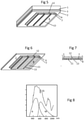
- the fragment of the figure 5 shows the curved thick sheet 1, the thermoplastic spacer 2 which ensures the assembly with the flat glass sheet 2 carrying the elements of the photovoltaic system.
- This comprises on the one hand the semiconductor layer 7, for example based on silicon, and two electrodes on either side 6 and 8.
- Electrode 6 is essentially transparent. It is advantageously formed of a layer of thin conductive oxide (TCO). These layers, which are well known in the field, are ordinarily applied directly to the glass sheet, and most often at the time of production of this sheet at the exit of the “floats”. The application is advantageously carried out by gaseous pyrolysis (CVD). But other techniques are also suitable, in particular vacuum sputtering techniques. Layers of this type are, for example, layers of fluorine-doped tin oxide, or of indium tin oxide (ITO).
- TCO thin conductive oxide
- the TCO layers have thicknesses of a few nanometers or tens of nanometers and are very weakly absorbent. They cover with uniformly the surface of the glass sheet 2, but can also have a cutout according to a determined pattern to form a compartmentalized conductive circuit.
- the pattern is for example formed by ablation from the uniform layer, along lines shown at 12.
- Semiconductor material 7 is applied directly to the conductive layer.
- the layer 7 is much less conductive than the TCO layer so that if this layer 7 fills the lines 12 cut in the layer 6 and comes into contact with the sheet 2, the cell elements nevertheless appear as distinct according to the cut of the lines 12 .
- the schematic representation does not show the layer 7 in contact with the sheet 2 for simplicity of reading these figures. This is not the case of the representation made of these layers at the figure 7 .
- the modes of production of the semiconductor layers are analogous to the previous ones, CVD, cathodic sputtering... .
- the light absorption of these two structures being sufficiently differentiated.
- the graph of the figure 8 illustrates the two types of absorption and their complementarity.
- the superposition of two layers, one of amorphous silicon, the other of microcrystalline silicon, improves the efficiency of the system significantly, while maintaining relatively thin thicknesses of the order of a few micrometers.
- Electrodes of this type are optionally conductive oxide layers sufficiently reflective, for example layers based on ZnO doped with aluminum, gallium or boron. They may also be systems further comprising a layer forming a mirror.
- the semiconductor layer (or layers) is optionally composed of juxtaposed elements to form an assembly capable of supplying the desired voltage as illustrated in figures 5, 6 and 7 .
- this light transmission is maintained between 5 and 30% of the incident light and advantageously from 8 to 20%.
- the semiconductor layers as well as the electrodes 8 being essentially opaque, it is necessary to break their continuity.
- the figures 5 and 6 show photovoltaic elements individualized by lines 13 which break layers 7 and 8. These lines are traced either directly during the formation of the layers by masking elements, or on uniform layers by localized ablation, for example by techniques putting using lasers.
- the presence of fine lines 12 may be insufficient to obtain the required level of transmission.
- the presence of wider lines could lead to excessively accentuated contrasts, making perceptible the absence of uniformity in the transmission on the surface considered.
- openings 11 in the layers of the photovoltaic systems can also be obtained like lines, in particular by laser ablation.
- the figure 7 shows in section a distribution of lines 12 and 13, and openings 11 in layers 6, and 7 and 8.
- the lines and apertures are themselves distributed as evenly as possible over this surface.
Landscapes
- Chemical & Material Sciences (AREA)
- Engineering & Computer Science (AREA)
- Life Sciences & Earth Sciences (AREA)
- Chemical Kinetics & Catalysis (AREA)
- General Chemical & Material Sciences (AREA)
- Geochemistry & Mineralogy (AREA)
- Materials Engineering (AREA)
- Organic Chemistry (AREA)
- Mechanical Engineering (AREA)
- Ceramic Engineering (AREA)
- Photovoltaic Devices (AREA)
Claims (18)
- Verfahren zur Herstellung einer ein Dach bildenden Fahrzeugverglasung, umfassend eine Anordnung aus Scheiben (1, 5) aus gebogenem Glas, die mittels von thermoplastischen Zwischenlagen (3, 4) zu einem Verbundsicherheitsglas verbunden sind, wobei mindestens ein Teil dieser Anordnung eine Photovoltaik-Vorrichtung (2) beinhaltet, die aus einer oder mehreren halbleitenden Schichten und auf beiden Seiten aus dünnen leitenden Schichten, die Elektroden bilden, aufgebaut ist, wobei in dem Dach mindestens der Teil der Photovoltaik-Vorrichtung, der die halbleitende(n) Schicht(en) umfasst, auf einer im Wesentlichen flachen Glasscheibe (2) aufgebaut ist, deren Dicke nicht mehr als 1 mm beträgt und die, in dem Verbundsicherheitsglasverband, mindestens einer zuvor gebogenen dickeren Glasscheibe zugeordnet ist.
- Verfahren zur Herstellung einer Verglasung nach Anspruch 1, bei dem das Material der halbleitenden Schichten der Photovoltaik-Anordnung auf der Basis von Silicium ist.
- Verfahren zur Herstellung einer Verglasung nach einem der vorhergehenden Ansprüche, bei dem die flache Scheibe, auf der die halbleitende(n) Schichten(en) aufgebaut ist(sind), eine Dicke aufweist, die nicht mehr als 1 mm, bevorzugt nicht mehr als 0,6 mm und besonders bevorzugt nicht mehr als 0,4 mm beträgt.
- Verfahren zur Herstellung einer Verglasung nach einem der vorhergehenden Ansprüche, bei dem die Dicke der flachen Scheibe nicht mehr als ein Drittel der Dicke der gebogenen Scheibe oder der Summe der Dicken der gebogenen Scheiben beträgt.
- Verfahren zur Herstellung einer Verglasung nach einem der vorhergehenden Ansprüche, bei dem eine einzige gebogene Scheibe vorhanden ist, wobei deren Dicke 3,2 mm und bevorzugt 2,1 mm nicht übersteigt.
- Verfahren zur Herstellung einer Verglasung nach einem der Ansprüche 1 bis 4, die in den Aufbau eines Fahrzeugdachs eingeht, bei dem in dem Verbund zwei gebogene Scheiben verwendet werden, wobei die Gesamtdicke dieser beiden Scheiben nicht mehr als 4,8 mm, bevorzugt nicht mehr als 4,2 mm beträgt.
- Verfahren zur Herstellung einer Verglasung nach Anspruch 6, bei dem keine der gebogenen Scheiben eine Dicke von mehr als 2,6 mm und bevorzugt von mehr als 2,1 mm aufweist.
- Verfahren zur Herstellung einer Verglasung nach einem der vorhergehenden Ansprüche, bei dem der kleinste Krümmungsradius, welcher der flachen Scheibe in dem Verbund mit einer oder mehreren zuvor gebogenen Scheiben aufgeprägt wird, nicht weniger als 2 m beträgt.
- Verfahren zur Herstellung einer Verglasung nach einem der vorhergehenden Ansprüche, bei dem die flache Scheibe, welche die Photovoltaik-Vorrichtung trägt, eine Scheibe aus chemisch vorgespanntem Glas ist.
- Verfahren zur Herstellung einer Verglasung nach einem der vorhergehenden Ansprüche, bei dem die Krümmungen, die der flachen Glasscheibe aufgeprägt werden, zu keinen Dehnbeanspruchungen von mehr als 10 Mpa bei nicht vorgespannten Scheiben und von mehr als 50 Mpa bei vorgespannten Scheiben führen.
- Verfahren zur Herstellung einer Verglasung nach einem der Ansprüche 6 bis 10, bei dem die Struktur ausgehend von der Außenseite eine erste zuvor gebogene Glasscheibe, eine thermoplastische Zwischenlagenfolie, eine die Schichten der Photovoltaik-Vorrichtung tragende Glasscheibe, eine zweite thermoplastische Zwischenlagenfolie, eine zweite zuvor gebogene Glasscheibe umfasst.
- Verfahren zur Herstellung einer Verglasung nach Anspruch 11, bei dem sich die Glasscheibe, welche die Schichten der Photovoltaik-Vorrichtung trägt, nur über einen Teil der Fläche des Dachs erstreckt, der nicht weniger als 50 % der Gesamtfläche beträgt.
- Verfahren zur Herstellung einer Verglasung nach Anspruch 12, bei dem die Glasscheibe, welche die Schichten der Photovoltaik-Vorrichtung trägt, in dem Teil angeordnet ist, der die geringsten Krümmungen aufweist.
- Verfahren zur Herstellung einer Verglasung nach einem der vorhergehenden Ansprüche, bei dem die leitenden Schichten, die Elektroden bilden, mindestens eine für sichtbare Strahlung im Wesentlichen transparente dünne Oxidschicht (TCO) umfassen, wobei diese Schicht in Einstrahlungsrichtung über der oder den halbleitenden Schicht(en) angeordnet ist.
- Verfahren zur Herstellung einer Verglasung nach einem der vorhergehenden Ansprüche, bei dem die leitende Schicht, die auf der Seite der halbleitende(n) Schichten (en) gelegen ist, auf der zur Einstrahlungsrichtung entgegengesetzten Seite eine Schicht aus leitendem Oxid und eine Metallschicht, welche die beim Passieren der halbleitenden Schicht nicht absorbierte Strahlung mindestens teilweise reflektiert, beinhaltet.
- Verfahren zur Herstellung einer Verglasung nach einem der vorhergehenden Ansprüche, bei dem die Photovoltaik-Vorrichtung eine Anordnung aus zwei Schichten umfasst, von denen die eine aus amorphem Silicium, die andere aus mikrokristallinem Silicium aufgebaut ist.
- Verfahren zur Herstellung einer Verglasung nach einem der vorhergehenden Ansprüche, bei dem die Lichttransmission zwischen 5 und 30 %, bevorzugt zwischen 8 und 20 % in dem Teil, der die Photovoltaik-Vorrichtung beinhaltet, aufrechterhalten wird durch Unterbrechungen dieser Vorrichtung, welche die Form von Linien und/oder punktuellen Fehlstellen der Beschichtung der Scheibe, die diese Vorrichtung stützt, aufweisen.
- Verfahren zur Herstellung einer Verglasung nach Anspruch 17, bei dem die Unterbrechungen durch Ablation mittels Laer und/oder durch Maskieren zum Zeitpunkt des Aufbaus dieser Schichten ausgeführt werden.
Applications Claiming Priority (2)
| Application Number | Priority Date | Filing Date | Title |
|---|---|---|---|
| BE2012/0036A BE1020460A3 (fr) | 2012-01-16 | 2012-01-16 | Vitrage photovoltaique. |
| PCT/EP2013/050549 WO2013107706A1 (fr) | 2012-01-16 | 2013-01-14 | Vitrage photovoltaique |
Publications (2)
| Publication Number | Publication Date |
|---|---|
| EP2804754A1 EP2804754A1 (de) | 2014-11-26 |
| EP2804754B1 true EP2804754B1 (de) | 2022-03-23 |
Family
ID=47557163
Family Applications (1)
| Application Number | Title | Priority Date | Filing Date |
|---|---|---|---|
| EP13700226.7A Active EP2804754B1 (de) | 2012-01-16 | 2013-01-14 | Photovoltaische verglasung |
Country Status (4)
| Country | Link |
|---|---|
| EP (1) | EP2804754B1 (de) |
| CN (1) | CN104093564B (de) |
| BE (1) | BE1020460A3 (de) |
| WO (1) | WO2013107706A1 (de) |
Families Citing this family (9)
| Publication number | Priority date | Publication date | Assignee | Title |
|---|---|---|---|---|
| WO2016021151A1 (ja) * | 2014-08-04 | 2016-02-11 | パナソニックIpマネジメント株式会社 | 太陽電池モジュールの製造方法 |
| JP6668823B2 (ja) * | 2015-04-08 | 2020-03-18 | Agc株式会社 | 合わせ板 |
| CN110088059B (zh) * | 2016-12-21 | 2021-12-31 | 株式会社Lg化学 | 弯曲夹层玻璃的制造方法及弯曲夹层玻璃 |
| GB201701272D0 (en) * | 2017-01-25 | 2017-03-08 | Pilkington Group Ltd | Process |
| DE202018006739U1 (de) | 2017-02-20 | 2022-07-20 | Corning Incorporated | Geformte Glaslaminate |
| EP3697735A1 (de) | 2017-10-18 | 2020-08-26 | Corning Incorporated | Verfahren zur steuerung der trennung zwischen gläsern während der gemeinsamen absenkung zur verringerung der endformdiskrepanz zwischen diesen |
| KR102200636B1 (ko) * | 2018-05-21 | 2021-01-11 | 주식회사 엘지화학 | 곡면 접합 유리의 제조 방법과 이에 의해 제조된 곡면 접합 유리 |
| WO2020021269A1 (en) * | 2018-07-25 | 2020-01-30 | Pilkington Group Limited | Process |
| CN120247420B (zh) * | 2025-04-15 | 2025-10-17 | 徐州宇辰玻璃科技有限公司 | 一种玻璃的镀膜装置及其工艺 |
Citations (1)
| Publication number | Priority date | Publication date | Assignee | Title |
|---|---|---|---|---|
| FR2413232A1 (fr) * | 1977-12-29 | 1979-07-27 | Bfg Glassgroup | Pare-brise a plaque interieure en verre silicate precontraint chimiquement |
Family Cites Families (6)
| Publication number | Priority date | Publication date | Assignee | Title |
|---|---|---|---|---|
| DE3538986C3 (de) * | 1985-11-02 | 1994-11-24 | Deutsche Aerospace | Verfahren zur Herstellung eines Solargenerators |
| DE68911201T2 (de) * | 1988-05-24 | 1994-06-16 | Asahi Glass Co Ltd | Methode für die Herstellung eines Solarzellenglassubstrates. |
| WO2003005457A1 (en) * | 2001-07-04 | 2003-01-16 | Ebara Corporation | Solar cell module and method of manufacturing the same |
| JP2005158801A (ja) * | 2003-11-20 | 2005-06-16 | Sharp Corp | 太陽電池モジュール及びその製造方法 |
| NL1031941C2 (nl) * | 2006-06-02 | 2007-12-04 | Movares Nederland Bv | Koud gebogen zonnepaneel. |
| US20120037229A1 (en) * | 2008-05-30 | 2012-02-16 | David Francis Dawson-Elli | Photovoltaic glass laminated articles and layered articles |
-
2012
- 2012-01-16 BE BE2012/0036A patent/BE1020460A3/fr active
-
2013
- 2013-01-14 CN CN201380005596.8A patent/CN104093564B/zh active Active
- 2013-01-14 WO PCT/EP2013/050549 patent/WO2013107706A1/fr not_active Ceased
- 2013-01-14 EP EP13700226.7A patent/EP2804754B1/de active Active
Patent Citations (1)
| Publication number | Priority date | Publication date | Assignee | Title |
|---|---|---|---|---|
| FR2413232A1 (fr) * | 1977-12-29 | 1979-07-27 | Bfg Glassgroup | Pare-brise a plaque interieure en verre silicate precontraint chimiquement |
Also Published As
| Publication number | Publication date |
|---|---|
| CN104093564A (zh) | 2014-10-08 |
| CN104093564B (zh) | 2017-08-15 |
| BE1020460A3 (fr) | 2013-10-01 |
| WO2013107706A1 (fr) | 2013-07-25 |
| EP2804754A1 (de) | 2014-11-26 |
Similar Documents
| Publication | Publication Date | Title |
|---|---|---|
| EP2804754B1 (de) | Photovoltaische verglasung | |
| EP1425124B1 (de) | Funktionalisierte verbundglasscheibe | |
| EP1776612B1 (de) | Elektrochemisches system mit mindestens einer teilmontagezone | |
| EP2729303B1 (de) | Glasscheibe für ein kraftfahrzeug | |
| CA2637247C (fr) | Vitrage transparent muni d'un systeme stratifie chauffant | |
| EP1171294B1 (de) | Kraftfahrzeugdach | |
| EP3717239B1 (de) | Fahrzeugsonnendach, fahrzeug damit und dessen herstellung | |
| EP1952194B1 (de) | Elektrochromes system auf einem kunststoffsubstrat | |
| EP2861422B1 (de) | Glasdach mit leuchtmitteln und solchen zur kontrolle der lichttransmission | |
| EP2861421B1 (de) | Glasdach mit leuchtvorrichtung | |
| BE1020717A3 (fr) | Toit de vehicule. | |
| EP1651433A2 (de) | Funktionalisierte sicherheitsverglasung | |
| EP1029662B1 (de) | Verbundglasscheibe | |
| FR2962682A1 (fr) | Vitrage electrochimique a proprietes optiques et/ou energetiques electrocommandables | |
| EP1200256A1 (de) | Verglasung insbesondere für ein fahrzeugdach | |
| FR3053922A1 (fr) | Vitrage feuillete a verre interieur tres mince en retrait | |
| EP0839644A1 (de) | Wärmestrahlenreflektierende Verbundglasscheibe und Verfahren zu ihrer Herstellung | |
| EP4222126A1 (de) | Hochfrequenztransparente solarsteuernde heizverglasung | |
| WO2025104144A1 (fr) | Ensemble a diffusion ou transparence commutable, a segments visible(s) et non visible(s) | |
| BE1013099A3 (fr) | Vitrage pour toit de vehicule automobile: | |
| FR3163892A1 (fr) | Vitrage feuillete photovoltaïque transparent a confort thermique et de couleur neutre en transmission | |
| EP0364372A1 (de) | Transparentes Verbundsicherheitsglas | |
| FR3085882A1 (fr) | Vitrage feuillete a element fonctionnel integre |
Legal Events
| Date | Code | Title | Description |
|---|---|---|---|
| PUAI | Public reference made under article 153(3) epc to a published international application that has entered the european phase |
Free format text: ORIGINAL CODE: 0009012 |
|
| 17P | Request for examination filed |
Effective date: 20140818 |
|
| AK | Designated contracting states |
Kind code of ref document: A1 Designated state(s): AL AT BE BG CH CY CZ DE DK EE ES FI FR GB GR HR HU IE IS IT LI LT LU LV MC MK MT NL NO PL PT RO RS SE SI SK SM TR |
|
| DAX | Request for extension of the european patent (deleted) | ||
| STAA | Information on the status of an ep patent application or granted ep patent |
Free format text: STATUS: EXAMINATION IS IN PROGRESS |
|
| 17Q | First examination report despatched |
Effective date: 20190506 |
|
| GRAP | Despatch of communication of intention to grant a patent |
Free format text: ORIGINAL CODE: EPIDOSNIGR1 |
|
| STAA | Information on the status of an ep patent application or granted ep patent |
Free format text: STATUS: GRANT OF PATENT IS INTENDED |
|
| INTG | Intention to grant announced |
Effective date: 20211022 |
|
| RIC1 | Information provided on ipc code assigned before grant |
Ipc: C03C 27/10 20060101ALI20211011BHEP Ipc: H01L 27/142 20140101ALI20211011BHEP Ipc: C03C 17/22 20060101ALI20211011BHEP Ipc: H01L 31/048 20140101ALI20211011BHEP Ipc: B32B 17/10 20060101AFI20211011BHEP |
|
| GRAS | Grant fee paid |
Free format text: ORIGINAL CODE: EPIDOSNIGR3 |
|
| GRAA | (expected) grant |
Free format text: ORIGINAL CODE: 0009210 |
|
| STAA | Information on the status of an ep patent application or granted ep patent |
Free format text: STATUS: THE PATENT HAS BEEN GRANTED |
|
| AK | Designated contracting states |
Kind code of ref document: B1 Designated state(s): AL AT BE BG CH CY CZ DE DK EE ES FI FR GB GR HR HU IE IS IT LI LT LU LV MC MK MT NL NO PL PT RO RS SE SI SK SM TR |
|
| REG | Reference to a national code |
Ref country code: GB Ref legal event code: FG4D Free format text: NOT ENGLISH |
|
| REG | Reference to a national code |
Ref country code: CH Ref legal event code: EP |
|
| REG | Reference to a national code |
Ref country code: DE Ref legal event code: R096 Ref document number: 602013081172 Country of ref document: DE |
|
| REG | Reference to a national code |
Ref country code: IE Ref legal event code: FG4D Free format text: LANGUAGE OF EP DOCUMENT: FRENCH |
|
| REG | Reference to a national code |
Ref country code: AT Ref legal event code: REF Ref document number: 1477170 Country of ref document: AT Kind code of ref document: T Effective date: 20220415 |
|
| REG | Reference to a national code |
Ref country code: LT Ref legal event code: MG9D |
|
| REG | Reference to a national code |
Ref country code: NL Ref legal event code: MP Effective date: 20220323 |
|
| PG25 | Lapsed in a contracting state [announced via postgrant information from national office to epo] |
Ref country code: SE Free format text: LAPSE BECAUSE OF FAILURE TO SUBMIT A TRANSLATION OF THE DESCRIPTION OR TO PAY THE FEE WITHIN THE PRESCRIBED TIME-LIMIT Effective date: 20220323 Ref country code: RS Free format text: LAPSE BECAUSE OF FAILURE TO SUBMIT A TRANSLATION OF THE DESCRIPTION OR TO PAY THE FEE WITHIN THE PRESCRIBED TIME-LIMIT Effective date: 20220323 Ref country code: NO Free format text: LAPSE BECAUSE OF FAILURE TO SUBMIT A TRANSLATION OF THE DESCRIPTION OR TO PAY THE FEE WITHIN THE PRESCRIBED TIME-LIMIT Effective date: 20220623 Ref country code: LT Free format text: LAPSE BECAUSE OF FAILURE TO SUBMIT A TRANSLATION OF THE DESCRIPTION OR TO PAY THE FEE WITHIN THE PRESCRIBED TIME-LIMIT Effective date: 20220323 Ref country code: HR Free format text: LAPSE BECAUSE OF FAILURE TO SUBMIT A TRANSLATION OF THE DESCRIPTION OR TO PAY THE FEE WITHIN THE PRESCRIBED TIME-LIMIT Effective date: 20220323 Ref country code: BG Free format text: LAPSE BECAUSE OF FAILURE TO SUBMIT A TRANSLATION OF THE DESCRIPTION OR TO PAY THE FEE WITHIN THE PRESCRIBED TIME-LIMIT Effective date: 20220623 |
|
| REG | Reference to a national code |
Ref country code: AT Ref legal event code: MK05 Ref document number: 1477170 Country of ref document: AT Kind code of ref document: T Effective date: 20220323 |
|
| PG25 | Lapsed in a contracting state [announced via postgrant information from national office to epo] |
Ref country code: LV Free format text: LAPSE BECAUSE OF FAILURE TO SUBMIT A TRANSLATION OF THE DESCRIPTION OR TO PAY THE FEE WITHIN THE PRESCRIBED TIME-LIMIT Effective date: 20220323 Ref country code: GR Free format text: LAPSE BECAUSE OF FAILURE TO SUBMIT A TRANSLATION OF THE DESCRIPTION OR TO PAY THE FEE WITHIN THE PRESCRIBED TIME-LIMIT Effective date: 20220624 Ref country code: FI Free format text: LAPSE BECAUSE OF FAILURE TO SUBMIT A TRANSLATION OF THE DESCRIPTION OR TO PAY THE FEE WITHIN THE PRESCRIBED TIME-LIMIT Effective date: 20220323 |
|
| PG25 | Lapsed in a contracting state [announced via postgrant information from national office to epo] |
Ref country code: NL Free format text: LAPSE BECAUSE OF FAILURE TO SUBMIT A TRANSLATION OF THE DESCRIPTION OR TO PAY THE FEE WITHIN THE PRESCRIBED TIME-LIMIT Effective date: 20220323 |
|
| PG25 | Lapsed in a contracting state [announced via postgrant information from national office to epo] |
Ref country code: SM Free format text: LAPSE BECAUSE OF FAILURE TO SUBMIT A TRANSLATION OF THE DESCRIPTION OR TO PAY THE FEE WITHIN THE PRESCRIBED TIME-LIMIT Effective date: 20220323 Ref country code: SK Free format text: LAPSE BECAUSE OF FAILURE TO SUBMIT A TRANSLATION OF THE DESCRIPTION OR TO PAY THE FEE WITHIN THE PRESCRIBED TIME-LIMIT Effective date: 20220323 Ref country code: RO Free format text: LAPSE BECAUSE OF FAILURE TO SUBMIT A TRANSLATION OF THE DESCRIPTION OR TO PAY THE FEE WITHIN THE PRESCRIBED TIME-LIMIT Effective date: 20220323 Ref country code: PT Free format text: LAPSE BECAUSE OF FAILURE TO SUBMIT A TRANSLATION OF THE DESCRIPTION OR TO PAY THE FEE WITHIN THE PRESCRIBED TIME-LIMIT Effective date: 20220725 Ref country code: ES Free format text: LAPSE BECAUSE OF FAILURE TO SUBMIT A TRANSLATION OF THE DESCRIPTION OR TO PAY THE FEE WITHIN THE PRESCRIBED TIME-LIMIT Effective date: 20220323 Ref country code: EE Free format text: LAPSE BECAUSE OF FAILURE TO SUBMIT A TRANSLATION OF THE DESCRIPTION OR TO PAY THE FEE WITHIN THE PRESCRIBED TIME-LIMIT Effective date: 20220323 Ref country code: CZ Free format text: LAPSE BECAUSE OF FAILURE TO SUBMIT A TRANSLATION OF THE DESCRIPTION OR TO PAY THE FEE WITHIN THE PRESCRIBED TIME-LIMIT Effective date: 20220323 Ref country code: AT Free format text: LAPSE BECAUSE OF FAILURE TO SUBMIT A TRANSLATION OF THE DESCRIPTION OR TO PAY THE FEE WITHIN THE PRESCRIBED TIME-LIMIT Effective date: 20220323 |
|
| PG25 | Lapsed in a contracting state [announced via postgrant information from national office to epo] |
Ref country code: PL Free format text: LAPSE BECAUSE OF FAILURE TO SUBMIT A TRANSLATION OF THE DESCRIPTION OR TO PAY THE FEE WITHIN THE PRESCRIBED TIME-LIMIT Effective date: 20220323 Ref country code: IS Free format text: LAPSE BECAUSE OF FAILURE TO SUBMIT A TRANSLATION OF THE DESCRIPTION OR TO PAY THE FEE WITHIN THE PRESCRIBED TIME-LIMIT Effective date: 20220723 Ref country code: AL Free format text: LAPSE BECAUSE OF FAILURE TO SUBMIT A TRANSLATION OF THE DESCRIPTION OR TO PAY THE FEE WITHIN THE PRESCRIBED TIME-LIMIT Effective date: 20220323 |
|
| REG | Reference to a national code |
Ref country code: DE Ref legal event code: R097 Ref document number: 602013081172 Country of ref document: DE |
|
| PLBE | No opposition filed within time limit |
Free format text: ORIGINAL CODE: 0009261 |
|
| STAA | Information on the status of an ep patent application or granted ep patent |
Free format text: STATUS: NO OPPOSITION FILED WITHIN TIME LIMIT |
|
| PG25 | Lapsed in a contracting state [announced via postgrant information from national office to epo] |
Ref country code: DK Free format text: LAPSE BECAUSE OF FAILURE TO SUBMIT A TRANSLATION OF THE DESCRIPTION OR TO PAY THE FEE WITHIN THE PRESCRIBED TIME-LIMIT Effective date: 20220323 |
|
| 26N | No opposition filed |
Effective date: 20230102 |
|
| PG25 | Lapsed in a contracting state [announced via postgrant information from national office to epo] |
Ref country code: SI Free format text: LAPSE BECAUSE OF FAILURE TO SUBMIT A TRANSLATION OF THE DESCRIPTION OR TO PAY THE FEE WITHIN THE PRESCRIBED TIME-LIMIT Effective date: 20220323 |
|
| REG | Reference to a national code |
Ref country code: CH Ref legal event code: PL |
|
| PG25 | Lapsed in a contracting state [announced via postgrant information from national office to epo] |
Ref country code: LU Free format text: LAPSE BECAUSE OF NON-PAYMENT OF DUE FEES Effective date: 20230114 |
|
| REG | Reference to a national code |
Ref country code: BE Ref legal event code: MM Effective date: 20230131 |
|
| PG25 | Lapsed in a contracting state [announced via postgrant information from national office to epo] |
Ref country code: LI Free format text: LAPSE BECAUSE OF NON-PAYMENT OF DUE FEES Effective date: 20230131 Ref country code: CH Free format text: LAPSE BECAUSE OF NON-PAYMENT OF DUE FEES Effective date: 20230131 |
|
| PG25 | Lapsed in a contracting state [announced via postgrant information from national office to epo] |
Ref country code: BE Free format text: LAPSE BECAUSE OF NON-PAYMENT OF DUE FEES Effective date: 20230131 |
|
| PG25 | Lapsed in a contracting state [announced via postgrant information from national office to epo] |
Ref country code: IE Free format text: LAPSE BECAUSE OF NON-PAYMENT OF DUE FEES Effective date: 20230114 |
|
| PG25 | Lapsed in a contracting state [announced via postgrant information from national office to epo] |
Ref country code: MC Free format text: LAPSE BECAUSE OF FAILURE TO SUBMIT A TRANSLATION OF THE DESCRIPTION OR TO PAY THE FEE WITHIN THE PRESCRIBED TIME-LIMIT Effective date: 20220323 |
|
| PG25 | Lapsed in a contracting state [announced via postgrant information from national office to epo] |
Ref country code: MC Free format text: LAPSE BECAUSE OF FAILURE TO SUBMIT A TRANSLATION OF THE DESCRIPTION OR TO PAY THE FEE WITHIN THE PRESCRIBED TIME-LIMIT Effective date: 20220323 |
|
| P01 | Opt-out of the competence of the unified patent court (upc) registered |
Free format text: CASE NUMBER: APP_37368/2024 Effective date: 20240622 |
|
| PG25 | Lapsed in a contracting state [announced via postgrant information from national office to epo] |
Ref country code: CY Free format text: LAPSE BECAUSE OF FAILURE TO SUBMIT A TRANSLATION OF THE DESCRIPTION OR TO PAY THE FEE WITHIN THE PRESCRIBED TIME-LIMIT; INVALID AB INITIO Effective date: 20130114 |
|
| PG25 | Lapsed in a contracting state [announced via postgrant information from national office to epo] |
Ref country code: HU Free format text: LAPSE BECAUSE OF FAILURE TO SUBMIT A TRANSLATION OF THE DESCRIPTION OR TO PAY THE FEE WITHIN THE PRESCRIBED TIME-LIMIT; INVALID AB INITIO Effective date: 20130114 |
|
| PG25 | Lapsed in a contracting state [announced via postgrant information from national office to epo] |
Ref country code: TR Free format text: LAPSE BECAUSE OF FAILURE TO SUBMIT A TRANSLATION OF THE DESCRIPTION OR TO PAY THE FEE WITHIN THE PRESCRIBED TIME-LIMIT Effective date: 20220323 |
|
| PGFP | Annual fee paid to national office [announced via postgrant information from national office to epo] |
Ref country code: GB Payment date: 20251204 Year of fee payment: 14 |
|
| PGFP | Annual fee paid to national office [announced via postgrant information from national office to epo] |
Ref country code: FR Payment date: 20251208 Year of fee payment: 14 |
|
| PGFP | Annual fee paid to national office [announced via postgrant information from national office to epo] |
Ref country code: DE Payment date: 20251203 Year of fee payment: 14 |
|
| PGFP | Annual fee paid to national office [announced via postgrant information from national office to epo] |
Ref country code: IT Payment date: 20251219 Year of fee payment: 14 |