EP2804992B1 - Elektronischer lastabfallschutz für ein hydraulisches flüssigkeitssystem - Google Patents
Elektronischer lastabfallschutz für ein hydraulisches flüssigkeitssystem Download PDFInfo
- Publication number
- EP2804992B1 EP2804992B1 EP13701142.5A EP13701142A EP2804992B1 EP 2804992 B1 EP2804992 B1 EP 2804992B1 EP 13701142 A EP13701142 A EP 13701142A EP 2804992 B1 EP2804992 B1 EP 2804992B1
- Authority
- EP
- European Patent Office
- Prior art keywords
- port
- valve
- pressure
- supply pressure
- controller
- Prior art date
- Legal status (The legal status is an assumption and is not a legal conclusion. Google has not performed a legal analysis and makes no representation as to the accuracy of the status listed.)
- Not-in-force
Links
- 239000012530 fluid Substances 0.000 title claims description 22
- 238000000034 method Methods 0.000 claims description 17
- 238000005516 engineering process Methods 0.000 description 11
- 238000010586 diagram Methods 0.000 description 4
- 238000012544 monitoring process Methods 0.000 description 4
- 238000004590 computer program Methods 0.000 description 3
- 230000005484 gravity Effects 0.000 description 3
- 238000004519 manufacturing process Methods 0.000 description 3
- 238000010276 construction Methods 0.000 description 2
- 238000012986 modification Methods 0.000 description 2
- 230000004048 modification Effects 0.000 description 2
- 238000006243 chemical reaction Methods 0.000 description 1
- 230000006870 function Effects 0.000 description 1
- 230000010365 information processing Effects 0.000 description 1
- 238000009434 installation Methods 0.000 description 1
- 239000000463 material Substances 0.000 description 1
- 230000007246 mechanism Effects 0.000 description 1
Images


Classifications
-
- F—MECHANICAL ENGINEERING; LIGHTING; HEATING; WEAPONS; BLASTING
- F17—STORING OR DISTRIBUTING GASES OR LIQUIDS
- F17D—PIPE-LINE SYSTEMS; PIPE-LINES
- F17D3/00—Arrangements for supervising or controlling working operations
-
- E—FIXED CONSTRUCTIONS
- E02—HYDRAULIC ENGINEERING; FOUNDATIONS; SOIL SHIFTING
- E02F—DREDGING; SOIL-SHIFTING
- E02F9/00—Component parts of dredgers or soil-shifting machines, not restricted to one of the kinds covered by groups E02F3/00 - E02F7/00
- E02F9/20—Drives; Control devices
- E02F9/22—Hydraulic or pneumatic drives
- E02F9/2221—Control of flow rate; Load sensing arrangements
- E02F9/2232—Control of flow rate; Load sensing arrangements using one or more variable displacement pumps
- E02F9/2235—Control of flow rate; Load sensing arrangements using one or more variable displacement pumps including an electronic controller
-
- E—FIXED CONSTRUCTIONS
- E02—HYDRAULIC ENGINEERING; FOUNDATIONS; SOIL SHIFTING
- E02F—DREDGING; SOIL-SHIFTING
- E02F9/00—Component parts of dredgers or soil-shifting machines, not restricted to one of the kinds covered by groups E02F3/00 - E02F7/00
- E02F9/20—Drives; Control devices
- E02F9/22—Hydraulic or pneumatic drives
- E02F9/2264—Arrangements or adaptations of elements for hydraulic drives
- E02F9/2267—Valves or distributors
-
- F—MECHANICAL ENGINEERING; LIGHTING; HEATING; WEAPONS; BLASTING
- F15—FLUID-PRESSURE ACTUATORS; HYDRAULICS OR PNEUMATICS IN GENERAL
- F15B—SYSTEMS ACTING BY MEANS OF FLUIDS IN GENERAL; FLUID-PRESSURE ACTUATORS, e.g. SERVOMOTORS; DETAILS OF FLUID-PRESSURE SYSTEMS, NOT OTHERWISE PROVIDED FOR
- F15B21/00—Common features of fluid actuator systems; Fluid-pressure actuator systems or details thereof, not covered by any other group of this subclass
- F15B21/08—Servomotor systems incorporating electrically operated control means
- F15B21/087—Control strategy, e.g. with block diagram
-
- F—MECHANICAL ENGINEERING; LIGHTING; HEATING; WEAPONS; BLASTING
- F15—FLUID-PRESSURE ACTUATORS; HYDRAULICS OR PNEUMATICS IN GENERAL
- F15B—SYSTEMS ACTING BY MEANS OF FLUIDS IN GENERAL; FLUID-PRESSURE ACTUATORS, e.g. SERVOMOTORS; DETAILS OF FLUID-PRESSURE SYSTEMS, NOT OTHERWISE PROVIDED FOR
- F15B2211/00—Circuits for servomotor systems
- F15B2211/30—Directional control
- F15B2211/31—Directional control characterised by the positions of the valve element
- F15B2211/3105—Neutral or centre positions
- F15B2211/3111—Neutral or centre positions the pump port being closed in the centre position, e.g. so-called closed centre
-
- F—MECHANICAL ENGINEERING; LIGHTING; HEATING; WEAPONS; BLASTING
- F15—FLUID-PRESSURE ACTUATORS; HYDRAULICS OR PNEUMATICS IN GENERAL
- F15B—SYSTEMS ACTING BY MEANS OF FLUIDS IN GENERAL; FLUID-PRESSURE ACTUATORS, e.g. SERVOMOTORS; DETAILS OF FLUID-PRESSURE SYSTEMS, NOT OTHERWISE PROVIDED FOR
- F15B2211/00—Circuits for servomotor systems
- F15B2211/30—Directional control
- F15B2211/32—Directional control characterised by the type of actuation
- F15B2211/327—Directional control characterised by the type of actuation electrically or electronically
-
- F—MECHANICAL ENGINEERING; LIGHTING; HEATING; WEAPONS; BLASTING
- F15—FLUID-PRESSURE ACTUATORS; HYDRAULICS OR PNEUMATICS IN GENERAL
- F15B—SYSTEMS ACTING BY MEANS OF FLUIDS IN GENERAL; FLUID-PRESSURE ACTUATORS, e.g. SERVOMOTORS; DETAILS OF FLUID-PRESSURE SYSTEMS, NOT OTHERWISE PROVIDED FOR
- F15B2211/00—Circuits for servomotor systems
- F15B2211/60—Circuit components or control therefor
- F15B2211/63—Electronic controllers
- F15B2211/6303—Electronic controllers using input signals
- F15B2211/6306—Electronic controllers using input signals representing a pressure
- F15B2211/6309—Electronic controllers using input signals representing a pressure the pressure being a pressure source supply pressure
-
- F—MECHANICAL ENGINEERING; LIGHTING; HEATING; WEAPONS; BLASTING
- F15—FLUID-PRESSURE ACTUATORS; HYDRAULICS OR PNEUMATICS IN GENERAL
- F15B—SYSTEMS ACTING BY MEANS OF FLUIDS IN GENERAL; FLUID-PRESSURE ACTUATORS, e.g. SERVOMOTORS; DETAILS OF FLUID-PRESSURE SYSTEMS, NOT OTHERWISE PROVIDED FOR
- F15B2211/00—Circuits for servomotor systems
- F15B2211/60—Circuit components or control therefor
- F15B2211/63—Electronic controllers
- F15B2211/6303—Electronic controllers using input signals
- F15B2211/6306—Electronic controllers using input signals representing a pressure
- F15B2211/6313—Electronic controllers using input signals representing a pressure the pressure being a load pressure
-
- F—MECHANICAL ENGINEERING; LIGHTING; HEATING; WEAPONS; BLASTING
- F15—FLUID-PRESSURE ACTUATORS; HYDRAULICS OR PNEUMATICS IN GENERAL
- F15B—SYSTEMS ACTING BY MEANS OF FLUIDS IN GENERAL; FLUID-PRESSURE ACTUATORS, e.g. SERVOMOTORS; DETAILS OF FLUID-PRESSURE SYSTEMS, NOT OTHERWISE PROVIDED FOR
- F15B2211/00—Circuits for servomotor systems
- F15B2211/60—Circuit components or control therefor
- F15B2211/665—Methods of control using electronic components
-
- F—MECHANICAL ENGINEERING; LIGHTING; HEATING; WEAPONS; BLASTING
- F15—FLUID-PRESSURE ACTUATORS; HYDRAULICS OR PNEUMATICS IN GENERAL
- F15B—SYSTEMS ACTING BY MEANS OF FLUIDS IN GENERAL; FLUID-PRESSURE ACTUATORS, e.g. SERVOMOTORS; DETAILS OF FLUID-PRESSURE SYSTEMS, NOT OTHERWISE PROVIDED FOR
- F15B2211/00—Circuits for servomotor systems
- F15B2211/60—Circuit components or control therefor
- F15B2211/665—Methods of control using electronic components
- F15B2211/6652—Control of the pressure source, e.g. control of the swash plate angle
-
- F—MECHANICAL ENGINEERING; LIGHTING; HEATING; WEAPONS; BLASTING
- F15—FLUID-PRESSURE ACTUATORS; HYDRAULICS OR PNEUMATICS IN GENERAL
- F15B—SYSTEMS ACTING BY MEANS OF FLUIDS IN GENERAL; FLUID-PRESSURE ACTUATORS, e.g. SERVOMOTORS; DETAILS OF FLUID-PRESSURE SYSTEMS, NOT OTHERWISE PROVIDED FOR
- F15B2211/00—Circuits for servomotor systems
- F15B2211/60—Circuit components or control therefor
- F15B2211/665—Methods of control using electronic components
- F15B2211/6653—Pressure control
-
- Y—GENERAL TAGGING OF NEW TECHNOLOGICAL DEVELOPMENTS; GENERAL TAGGING OF CROSS-SECTIONAL TECHNOLOGIES SPANNING OVER SEVERAL SECTIONS OF THE IPC; TECHNICAL SUBJECTS COVERED BY FORMER USPC CROSS-REFERENCE ART COLLECTIONS [XRACs] AND DIGESTS
- Y10—TECHNICAL SUBJECTS COVERED BY FORMER USPC
- Y10T—TECHNICAL SUBJECTS COVERED BY FORMER US CLASSIFICATION
- Y10T137/00—Fluid handling
- Y10T137/0318—Processes
- Y10T137/0324—With control of flow by a condition or characteristic of a fluid
- Y10T137/0379—By fluid pressure
-
- Y—GENERAL TAGGING OF NEW TECHNOLOGICAL DEVELOPMENTS; GENERAL TAGGING OF CROSS-SECTIONAL TECHNOLOGIES SPANNING OVER SEVERAL SECTIONS OF THE IPC; TECHNICAL SUBJECTS COVERED BY FORMER USPC CROSS-REFERENCE ART COLLECTIONS [XRACs] AND DIGESTS
- Y10—TECHNICAL SUBJECTS COVERED BY FORMER USPC
- Y10T—TECHNICAL SUBJECTS COVERED BY FORMER US CLASSIFICATION
- Y10T137/00—Fluid handling
- Y10T137/8593—Systems
- Y10T137/85978—With pump
- Y10T137/85986—Pumped fluid control
- Y10T137/86002—Fluid pressure responsive
Definitions
- Hydraulic control systems of the prior art are disclosed in WO2012/109558A1 , US2008/0163750A1 and US2010/0095835A1 .
- Traditional hydraulic control systems use a mechanical check valve to ensure that a load that resists gravity does not move in the opposite direction of a command velocity. In this way, the check valve ensures that a supply pressure from a pump is higher than the port pressure on an associated actuator or cylinder.
- FIG. 1 One such hydraulic control system 100 is depicted in FIG. 1 .
- the system 100 includes a pump 102 that draws hydraulic fluid from a fluid reservoir 104. The pump discharge is forced upwards against the force of gravity G.
- a two-way valve 106 includes a first open position 106a, a second open position 106b, and a closed position 106c.
- first position 106a flow from the pump 102 is delivered to a first port 108 of a piston cylinder 110.
- the valve 106 is in the second position 106b, flow from the pump 102 is delivered to a second port 112 of the piston cylinder 110.
- the piston 114 moves within the cylinder 110, and hydraulic fluid is forced out of the opposite of the two ports 112, 108.
- the valve 106 is in the closed position 106c, flow into and out of the piston cylinder 110 is prevented.
- a check valve 116 is positioned between the outlet of the pump 102 and the valve 106. When the valve 106 is in the first position 106a, the check valve 116 prevents excessive head pressure from the fluid in the piston cylinder 110 from being forced back against the output flow of the pump 102. While check valves are often used in systems that pump fluid against the force of gravity, they are subject to fouling or damage that may prevent proper operation.
- the technology relates to a method of controlling a valve, the method including: detecting a supply pressure at a fluid source; detecting a first port pressure at a first side of a piston, the piston located in a cylinder; actuating the valve from a closed position to a first open position when the supply pressure is in excess of the first port pressure; and actuating the valve to the closed position when the supply pressure is less than the first port pressure.
- the technology in another aspect, relates to a hydraulic control system including: a piston cylinder; a pump connected to a source of hydraulic fluid; a valve located between the piston cylinder and the pump; a supply pressure sensor located on a fluid line at an outlet of the pump; a first port pressure sensor located on a fluid line at a first inlet of the piston cylinder; and a controller operatively connected to the valve, the supply pressure sensor, and the first port pressure sensor, wherein the controller sends a first signal to actuate the valve from a closed position to a first open position upon detecting a supply pressure higher than a first port pressure, and wherein the controller actuates the valve to the closed position when the supply pressure is less than the first port pressure.
- Hydraulic actuators are commonly used in industrial equipment and construction equipment (e.g., booms, lifts, swing arms, pivot mechanisms). For clarity, however, the following embodiments will be described in the context of hydraulic cylinders.
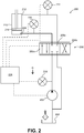
- FIG. 2 depicts a schematic of a hydraulic control system 200.
- the system includes a pump 202, a reservoir 204, and a two-way valve 206.
- the valve 206 which may be a metering valve, has a first open position 206a, a second open position 206b, and a closed position 206c.
- the position of the valve 206 controls fluid delivery to either a first port 208 or a second port 212 of a piston cylinder 210, thus moving the piston 214 accordingly. Fluid is also forced from the opposite port 212, 208 back to the reservoir 204, via the valve 206.
- the control system 200 includes a number of pressure sensors 218, 220, 222 that communicate with a controller 224.
- the controller 224 is also operatively connected to an actuator (not shown) that actuates the valve 206 between the various positions 206a, 206b, 206c.
- the controller 224 may also control and/or operation of the pump 202.
- the controller 224 continuously monitors signals indicative of the pump supply pressure that are sent from the supply pressure sensor 218. These signals are compared to signals continuously sent from the port pressure sensors 220, 222 that are indicative of the pressure at each port.
- the controller 224 maintains valve 206 in the closed position 206c, preventing that high fluid pressure from being directed towards the outlet of the pump 202.
- the controller continues to monitor the signals sent from the sensor 218 and sensor 220. Once the supply pressure is equal to or higher than the port pressure, the valve may open to a first valve position (in this case, to position 206a).
- metering valve 206 opens, pressures from the various sensors are constantly monitored. If the pressure at a port pressure sensor 220, 222 exceeds that of the supply pressure sensor 218, the controller 224 will actuate the valve to the closed position 206c, to prevent the load from falling backwards.
- the valve 206 may also be a metering valve.
- the controller 224 may throttle back the metering valve 206 as the difference (or margin) between the supply pressure and port pressure narrows. That is, as the port pressure increases relative to the supply pressure, the valve 206 will throttle back so as to avoid service/system saturation and to prevent the load from moving in the direction opposite of the command direction.
- FIG. 3 depicts a control logic diagram 300 for controlling a hydraulic control system, such as the type depicted in FIG. 2 .
- a first state (302) there is a non-zero flow demand and the flow direction is from the pump outlet (i.e., supply) to one of the cylinder ports.
- the pump outlet i.e., supply
- the port pressure sensors and supply pressure sensor are monitored until the supply pressure is greater than the port pressure (304). More specifically, the supply pressure is compared to the port pressure at the port to which the flow will be directed. If the supply pressure is, in fact, greater than the port pressure, the valve is actuated to an active state (306) and flow through the valve begins as the valve opens.
- the supply pressure may exceed the port pressure by a certain factor, percentage, or other parameter, prior to the valve being actuated to an open position.
- the supply pressure may exceed the first port pressure by about 5 bar prior to the valve being actuated. At higher flow rates greater margins between the supply pressure and port pressure may be desirable.
- the pressure sensors are continually monitored when the valve is in the active state. If the difference between the supply pressure and the appropriate port pressure is less than a margin or difference (308), the controller begins throttling back the valve (310) towards a closed position.
- This margin or difference may be predefined or otherwise configurable. The margin may be configured based on the desired or required performance considerations, operator preferences, or other factors. Throttling back of the valve may continue until the valve closes completely, or until the loads change, such that the difference between the supply pressure and the appropriate port pressure is greater than or equal to the configurable margin (312). In that case, the valve may return to its active state (306) and active sensor monitoring continues.
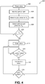
- FIG. 4 depicts a method 400 of controlling a hydraulic system.
- the method 400 begins with a closed metering valve (Step 402), such as the valve depicted in FIG. 2 , above.
- a cylinder port is identified (Step 404), either by an operator-controlled selector switch, or by an electronically-controlled switch.
- the proposed use of the cylinder will dictate which of the ports is identified.
- the identified port will define the port pressure P P to which the supply pressure P S will be compared during the method.
- the supply pressure P S is detected (Step 406) and a signal indicative of that pressure is sent to the controller.
- the port pressure P P is then detected (Step 408) and a signal indicative of that pressure is sent to the controller.
- Step 410 a comparison of the supply pressure P S and port pressure P P is made. If the supply pressure P S is less than the port pressure P P , the valve remains closed (and the control algorithm returns to Step 402). If the supply pressure P S is higher than the port pressure P P , the valve is opened (Step 412).
- the valve may be either opened completely or metered open, depending on a number of factors that may be programmed into the controller and/or user requirements. In this embodiment, the valve opens completely. Monitoring of the supply pressure P S and port pressure P P continues. If the supply pressure P S is not within a margin of the port pressure P P (Step 414), the valve remains open (i.e., the control algorithm returns to Step 412) and monitoring continues.
- Step 416 If the supply pressure P S is determined to be within a margin of the port pressure P P , however, the valve is throttled back (Step 416). If the valve has not throttled back so far as to be closed (Step 418), monitoring of the supply pressure P S and port pressure P P , and comparisons thereof, continue (as in Step 414). As the supply pressure P S differentiates from the port pressure P P by smaller and smaller margins, the valve continues to throttle back (as in Step 416). Once the valve has throttle back such that it is closed or nearly closed (Step 418), the algorithm confirms complete closure of the valve (Step 402) and awaits a new command signal.
- Different margins or differences may be programmed into the controller, either at the time of manufacture or in the field by the operator, as required or desired for a particular application. For example, opening of the valve to the first flow position may occur only when a FIRST OPENING MARGIN defined by a first value is reached. For the valve to open into the second flow position, a SECOND OPENING MARGIN, defined by a second value, may be required. Having different opening margins based on the side of the cylinder to which fluid is delivered may be advantageous in applications where safety or other considerations are present. Once the opening margin is reached, the valve may open completely in the active state, or may open to a minimum position.
- each of the margins may be defined by different values. In other embodiments, certain or all of the margins may be defined by the same valve. The margins may be characterized by absolute differences in pressure values, percentage differences, or other appropriate measures.
- the electronic sensors described herein are incorporated into a hydraulic control system that does not include a check valve.
- the sensors and controller may also be used in systems that have a mechanical check valve, as a redundant safety system.
- the control system may be used with valves having greater than or fewer than two positions, or in systems with multiple valves.
- the electronic control system described herein may be used in any hydraulic system where it is desirable to prevent or control backflow.
- the control system described herein may automatically move the valve to a closed position (either actively or by removing power from a spring-close actuator) when signals from one or more of the sensors are not received, or if the signals received may be indicative of an error condition.
- signals may be sent to and/or received by the controller at predetermined time intervals, which may be programmed during manufacture or in the field. Additionally, signals may be continuously sent to the controller, but the controller may only use a smaller subset of those signals for the required comparisons between supply pressure and port pressure.
- kits may include a controller, pressure sensors, pump, valve, etc.
- the controller may be sold as a single stand-alone unit. Users may then obtain the various valves, sensors, actuators, etc., separately from a third party or from the pump supplier.
- control wiring may be included, although instructions included with the kit may also specify the type of wiring required based on the particular installation.
- the electronic controller may be loaded with the necessary software or firmware required for use of the system.
- software may be included on various types of storage media (CDs, DVDs, USB drives, etc.) for upload to a standard PC, if the PC is to be used as the controller, or if the PC is used in conjunction with the control or pump system as a user or service interface.
- website addresses and passwords may be included in the kit instructions for programs to be downloaded from a website on the internet.
- control algorithm technology described herein can be realized in hardware, software, or a combination of hardware and software.
- the technology described herein can be realized in a centralized fashion in one computer system or in a distributed fashion where different elements are spread across several interconnected computer systems. Any kind of computer system or other apparatus adapted for carrying out the methods described herein is suitable.
- a typical combination of hardware and software can be a general purpose computer system with a computer program that, when being loaded and executed, controls the computer system such that it carries out the methods described herein. Since the technology is also contemplated to be used on heavy construction equipment, however, a stand-alone hardware system including the necessary operator interfaces (cylinder control switch, etc.) may be desirable.
- Computer program in the present context means any expression, in any language, code or notation, of a set of instructions intended to cause a system having an information processing capability to perform a particular function either directly or after either or both of the following: a) conversion to another language, code or notation; b) reproduction in a different material form.
Landscapes
- Engineering & Computer Science (AREA)
- General Engineering & Computer Science (AREA)
- Physics & Mathematics (AREA)
- Fluid Mechanics (AREA)
- Mining & Mineral Resources (AREA)
- Civil Engineering (AREA)
- Structural Engineering (AREA)
- Mechanical Engineering (AREA)
- Chemical & Material Sciences (AREA)
- Analytical Chemistry (AREA)
- Fluid-Pressure Circuits (AREA)
- Operation Control Of Excavators (AREA)
Claims (10)
- Verfahren zum Steuern eines Ventils (206), wobei das Verfahren umfasst:Detektieren eines Zulaufdrucks an einer Flüssigkeitsquelle (204);Identifizieren von einem von einem ersten Anschluss (208) an einer ersten Seite eines Kolbens (214) und einem zweiten Anschluss (212) an einer zweiten Seite des Kolbens, wobei sich der Kolben in einem Zylinder (210) befindet;Detektieren eines Anschlussdrucks an dem identifizierten ersten Anschluss (208) oder zweiten Anschluss (212);Stellen des Ventils (206) von einer geschlossenen Position (206c) auf eine erste offene Position (206a), wenn der erste Anschluss (208) der identifizierte Anschluss ist und der Zulaufdruck über dem ersten Anschlussdrucks liegt;Stellen des Ventils (206) von der geschlossenen Position (206c) auf eine zweite offene Position (206b), wenn der zweite Anschluss (212) der identifizierte Anschluss ist und der Zulaufdruck über dem zweiten Anschlussdrucks liegt; undStellen des Ventils von der ersten oder zweiten offenen Position (206a, 206b) auf die geschlossene Position (206c), wenn der Zulaufdruck kleiner als der erste beziehungsweise zweite Anschlussdruck ist.
- Verfahren nach Anspruch 1, wobei mindestens einer der Detektierungsschritte in vorbestimmten Intervallen stattfindet.
- Verfahren nach Anspruch 1, wobei mindestens einer der Detektierungsschritte kontinuierlich ist.
- Verfahren nach Anspruch 1, ferner umfassend Stellen des Ventils (206) auf die geschlossene Position (206c), wenn ein Unterschied zwischen dem Zulaufdruck und mindestens einem von dem ersten Anschlussdruck und dem zweiten Anschlussdruck einen vorbestimmten Parameter umfasst.
- Verfahren nach Anspruch 1, ferner umfassend Stellen des Ventils (206) auf die geschlossene Position (206c), wenn der Zulaufdruck etwa 5 bar größer als der erste Anschlussdruck ist.
- Hydraulisches Steuerungssystem, umfassend:einen Kolbenzylinder (214);eine Pumpe (202), die mit einer Quelle (204) für Hydraulikflüssigkeit verbunden ist;ein Ventil (206), welches sich zwischen dem Kolbenzylinder (210) und der Pumpe (202) befindet;einen Zulaufdrucksensor (218), der sich auf einer Flüssigkeitsleitung an einem Auslass der Pumpe (202) befindet;einen ersten Anschlussdrucksensor (220), der sich auf einer Flüssigkeitsleitung an einem ersten Einlass (208) des Kolbenzylinders (210) befindet;einen zweiten Anschlussdrucksensor (222), der sich auf einer Flüssigkeitsleitung an einem zweiten Einlass (212) des Kolbenzylinders (210) befindet; undeine Steuerung (224), die funktional mit dem Ventil (206), dem Zulaufdrucksensor (218) und dem ersten und zweiten Anschlussdrucksensor (220, 222) verbunden ist, wobeider erste Einlass (208) oder der zweite Einlass (212) identifiziert wird;dadurch gekennzeichnet, dass die Steuerung in einer solchen Weise konfiguriert ist, dass:wenn der erste Einlass (208) identifiziert ist, die Steuerung (224) ein erstes Signal sendet, um das Ventil (206) von einer geschlossenen Position (206c) zu einer ersten offenen Position (206a) zu stellen, wenn ein Zulaufdruck detektiert wird, der höher als ein erster Anschlussdruck ist,wenn der zweite Einlass (212) identifiziert ist, die Steuerung (224) ein zweites Signal sendet, um das Ventil (206) von einer geschlossenen Position (206c) zu einer zweiten offenen Position (206b) zu stellen, wenn ein Zulaufdruck detektiert wird, der höher als ein zweiter Anschlussdruck ist; undwobei die Steuerung (224) das Ventil (206) von der ersten oder zweiten offenen Position (206a, 206b) in die geschlossene Position (206c) stellt, wenn der Zulaufdruck kleiner als der erste Anschlussdruck beziehungsweise der zweite Anschlussdruck ist.
- Hydraulisches Steuerungssystem nach Anspruch 6, wobei die Steuerung (224) mindestens einen von dem Zulaufdruck und dem ersten Anschlussdruck in vorbestimmten Intervallen detektiert.
- Hydraulisches Steuerungssystem nach Anspruch 6, wobei die Steuerung (224) mindestens einen von dem Zulaufdruck und dem ersten Anschlussdruck kontinuierlich detektiert.
- Hydraulisches Steuerungssystem nach Anspruch 6, wobei die Steuerung (224) das Ventil (206) auf die geschlossene Position (206c) stellt, wenn ein Unterschied zwischen dem Zulaufdruck und mindestens einem von dem ersten Anschlussdruck und dem zweiten Anschlussdruck einen vorbestimmten Parameter umfasst.
- Hydraulisches Steuerungssystem nach Anspruch 6, wobei die Steuerung (224) das Ventil (206) auf die geschlossene Position (206c) stellt, wenn der Zulaufdruck etwa 5 bar größer als der erste Anschlussdruck ist.
Applications Claiming Priority (2)
| Application Number | Priority Date | Filing Date | Title |
|---|---|---|---|
| US201261588919P | 2012-01-20 | 2012-01-20 | |
| PCT/US2013/020343 WO2013109418A1 (en) | 2012-01-20 | 2013-01-04 | Electronic load drop protection for hydraulic fluid system |
Publications (2)
| Publication Number | Publication Date |
|---|---|
| EP2804992A1 EP2804992A1 (de) | 2014-11-26 |
| EP2804992B1 true EP2804992B1 (de) | 2018-12-12 |
Family
ID=47604175
Family Applications (1)
| Application Number | Title | Priority Date | Filing Date |
|---|---|---|---|
| EP13701142.5A Not-in-force EP2804992B1 (de) | 2012-01-20 | 2013-01-04 | Elektronischer lastabfallschutz für ein hydraulisches flüssigkeitssystem |
Country Status (6)
| Country | Link |
|---|---|
| US (1) | US20130186472A1 (de) |
| EP (1) | EP2804992B1 (de) |
| JP (1) | JP2015511296A (de) |
| CN (1) | CN104093915A (de) |
| CA (1) | CA2861902A1 (de) |
| WO (1) | WO2013109418A1 (de) |
Families Citing this family (3)
| Publication number | Priority date | Publication date | Assignee | Title |
|---|---|---|---|---|
| KR101881471B1 (ko) * | 2017-04-06 | 2018-07-24 | 주식회사 대흥이엔텍 | 안전밸브 시험장치 |
| US11572901B2 (en) * | 2020-03-16 | 2023-02-07 | Woodward, Inc. | Redundant electrohydraulic positioning control system |
| US12234925B2 (en) * | 2022-04-18 | 2025-02-25 | Emerson Automation Solutions Final Control US LP | Sensing arrangement for valves |
Family Cites Families (7)
| Publication number | Priority date | Publication date | Assignee | Title |
|---|---|---|---|---|
| US6598391B2 (en) * | 2001-08-28 | 2003-07-29 | Caterpillar Inc | Control for electro-hydraulic valve arrangement |
| US6662705B2 (en) * | 2001-12-10 | 2003-12-16 | Caterpillar Inc | Electro-hydraulic valve control system and method |
| US7518523B2 (en) * | 2007-01-05 | 2009-04-14 | Eaton Corporation | System and method for controlling actuator position |
| WO2009067050A1 (en) * | 2007-11-21 | 2009-05-28 | Volvo Construction Equipment Ab | Load sensing system, working machine comprising the system, and method for controlling a hydraulic function |
| CN102245491B (zh) * | 2008-10-16 | 2014-01-29 | 伊顿公司 | 作业车辆的动作控制 |
| US8352129B2 (en) * | 2008-10-16 | 2013-01-08 | Eaton Corporation | Motion control of work vehicle |
| CN103459860A (zh) * | 2011-02-10 | 2013-12-18 | 伊顿公司 | 具有在过载情况下的待机模式的负载传感控制 |
-
2013
- 2013-01-04 CN CN201380006140.3A patent/CN104093915A/zh active Pending
- 2013-01-04 CA CA 2861902 patent/CA2861902A1/en not_active Abandoned
- 2013-01-04 WO PCT/US2013/020343 patent/WO2013109418A1/en not_active Ceased
- 2013-01-04 EP EP13701142.5A patent/EP2804992B1/de not_active Not-in-force
- 2013-01-04 JP JP2014553313A patent/JP2015511296A/ja active Pending
- 2013-01-14 US US13/740,562 patent/US20130186472A1/en not_active Abandoned
Non-Patent Citations (1)
| Title |
|---|
| None * |
Also Published As
| Publication number | Publication date |
|---|---|
| WO2013109418A1 (en) | 2013-07-25 |
| CN104093915A (zh) | 2014-10-08 |
| CA2861902A1 (en) | 2013-07-25 |
| US20130186472A1 (en) | 2013-07-25 |
| EP2804992A1 (de) | 2014-11-26 |
| JP2015511296A (ja) | 2015-04-16 |
Similar Documents
| Publication | Publication Date | Title |
|---|---|---|
| EP2769103B1 (de) | Vorgesteuerte flüssigkeitsregulatoren mit einer rücksetzungsvorrichtung und zugehörige verfahren | |
| EP2881595B1 (de) | Vorrichtung für Notbetrieb von Aktuatoren | |
| RU2668504C2 (ru) | Позиционер клапана с возможностью защиты от избыточного давления | |
| BR112015007611B1 (pt) | método para detectar e isolar um vazamento em um sistema hidráulico, meio de armazenamento legível por computador e sistema hidráulico | |
| US20090277519A1 (en) | Method and apparatus for controlling fluid flow rate characteristics of a valve assembly | |
| WO2008084367A3 (en) | System and method for controlling actuator position | |
| US20130186472A1 (en) | Electronic load drop protection for hydraulic fluid system | |
| WO2022159477A9 (en) | Check valve testing systems and leak detection methods using the same | |
| JP6161634B2 (ja) | 油圧システムの負荷を一定に維持するシステムおよび方法 | |
| CN104285067A (zh) | 流体系统和用于运行流体系统的方法 | |
| Rannow | Fail operational controls for an independent metering valve | |
| EP3669084B1 (de) | System für den betrieb eines hydraulischen druckentlastungsventils | |
| EP2801724A1 (de) | Drucksystem zur vorbeugung von drucküberschreitung für eine elektronische hydraulikpumpe in einem hydraulischen system | |
| KR101862641B1 (ko) | 자동수격방지 기능을 가지는 전기유압식 밸브 액추에이터 시스템 | |
| KR20200057990A (ko) | Bldc 모터 제어장치 | |
| JP6291360B2 (ja) | 作業機械の油圧駆動装置 | |
| RU2821195C1 (ru) | Способ эксплуатации технологической установки и технологическая установка | |
| KR101546677B1 (ko) | 선박용 유압오일펌프의 오일 디스차징 자동 제어시스템 및 제어방법 | |
| US20140352822A1 (en) | Air bleed valve float arrangement with restrictor | |
| CN105843268A (zh) | 具有过压保护能力的阀定位器 |
Legal Events
| Date | Code | Title | Description |
|---|---|---|---|
| PUAI | Public reference made under article 153(3) epc to a published international application that has entered the european phase |
Free format text: ORIGINAL CODE: 0009012 |
|
| 17P | Request for examination filed |
Effective date: 20140805 |
|
| AK | Designated contracting states |
Kind code of ref document: A1 Designated state(s): AL AT BE BG CH CY CZ DE DK EE ES FI FR GB GR HR HU IE IS IT LI LT LU LV MC MK MT NL NO PL PT RO RS SE SI SK SM TR |
|
| DAX | Request for extension of the european patent (deleted) | ||
| STAA | Information on the status of an ep patent application or granted ep patent |
Free format text: STATUS: EXAMINATION IS IN PROGRESS |
|
| 17Q | First examination report despatched |
Effective date: 20170329 |
|
| REG | Reference to a national code |
Ref country code: DE Ref legal event code: R079 Ref document number: 602013048081 Country of ref document: DE Free format text: PREVIOUS MAIN CLASS: E02F0009220000 Ipc: F17D0003000000 |
|
| RIC1 | Information provided on ipc code assigned before grant |
Ipc: F15B 21/08 20060101ALI20180503BHEP Ipc: F17D 3/00 20060101AFI20180503BHEP Ipc: E02F 9/22 20060101ALI20180503BHEP |
|
| GRAP | Despatch of communication of intention to grant a patent |
Free format text: ORIGINAL CODE: EPIDOSNIGR1 |
|
| STAA | Information on the status of an ep patent application or granted ep patent |
Free format text: STATUS: GRANT OF PATENT IS INTENDED |
|
| INTG | Intention to grant announced |
Effective date: 20180621 |
|
| GRAS | Grant fee paid |
Free format text: ORIGINAL CODE: EPIDOSNIGR3 |
|
| GRAA | (expected) grant |
Free format text: ORIGINAL CODE: 0009210 |
|
| STAA | Information on the status of an ep patent application or granted ep patent |
Free format text: STATUS: THE PATENT HAS BEEN GRANTED |
|
| AK | Designated contracting states |
Kind code of ref document: B1 Designated state(s): AL AT BE BG CH CY CZ DE DK EE ES FI FR GB GR HR HU IE IS IT LI LT LU LV MC MK MT NL NO PL PT RO RS SE SI SK SM TR |
|
| REG | Reference to a national code |
Ref country code: GB Ref legal event code: FG4D |
|
| REG | Reference to a national code |
Ref country code: CH Ref legal event code: EP |
|
| REG | Reference to a national code |
Ref country code: AT Ref legal event code: REF Ref document number: 1076504 Country of ref document: AT Kind code of ref document: T Effective date: 20181215 |
|
| REG | Reference to a national code |
Ref country code: DE Ref legal event code: R096 Ref document number: 602013048081 Country of ref document: DE |
|
| REG | Reference to a national code |
Ref country code: IE Ref legal event code: FG4D |
|
| REG | Reference to a national code |
Ref country code: NL Ref legal event code: MP Effective date: 20181212 |
|
| REG | Reference to a national code |
Ref country code: LT Ref legal event code: MG4D |
|
| PG25 | Lapsed in a contracting state [announced via postgrant information from national office to epo] |
Ref country code: ES Free format text: LAPSE BECAUSE OF FAILURE TO SUBMIT A TRANSLATION OF THE DESCRIPTION OR TO PAY THE FEE WITHIN THE PRESCRIBED TIME-LIMIT Effective date: 20181212 Ref country code: LT Free format text: LAPSE BECAUSE OF FAILURE TO SUBMIT A TRANSLATION OF THE DESCRIPTION OR TO PAY THE FEE WITHIN THE PRESCRIBED TIME-LIMIT Effective date: 20181212 Ref country code: NO Free format text: LAPSE BECAUSE OF FAILURE TO SUBMIT A TRANSLATION OF THE DESCRIPTION OR TO PAY THE FEE WITHIN THE PRESCRIBED TIME-LIMIT Effective date: 20190312 Ref country code: BG Free format text: LAPSE BECAUSE OF FAILURE TO SUBMIT A TRANSLATION OF THE DESCRIPTION OR TO PAY THE FEE WITHIN THE PRESCRIBED TIME-LIMIT Effective date: 20190312 Ref country code: HR Free format text: LAPSE BECAUSE OF FAILURE TO SUBMIT A TRANSLATION OF THE DESCRIPTION OR TO PAY THE FEE WITHIN THE PRESCRIBED TIME-LIMIT Effective date: 20181212 Ref country code: LV Free format text: LAPSE BECAUSE OF FAILURE TO SUBMIT A TRANSLATION OF THE DESCRIPTION OR TO PAY THE FEE WITHIN THE PRESCRIBED TIME-LIMIT Effective date: 20181212 Ref country code: FI Free format text: LAPSE BECAUSE OF FAILURE TO SUBMIT A TRANSLATION OF THE DESCRIPTION OR TO PAY THE FEE WITHIN THE PRESCRIBED TIME-LIMIT Effective date: 20181212 |
|
| REG | Reference to a national code |
Ref country code: AT Ref legal event code: MK05 Ref document number: 1076504 Country of ref document: AT Kind code of ref document: T Effective date: 20181212 |
|
| PG25 | Lapsed in a contracting state [announced via postgrant information from national office to epo] |
Ref country code: RS Free format text: LAPSE BECAUSE OF FAILURE TO SUBMIT A TRANSLATION OF THE DESCRIPTION OR TO PAY THE FEE WITHIN THE PRESCRIBED TIME-LIMIT Effective date: 20181212 Ref country code: AL Free format text: LAPSE BECAUSE OF FAILURE TO SUBMIT A TRANSLATION OF THE DESCRIPTION OR TO PAY THE FEE WITHIN THE PRESCRIBED TIME-LIMIT Effective date: 20181212 Ref country code: SE Free format text: LAPSE BECAUSE OF FAILURE TO SUBMIT A TRANSLATION OF THE DESCRIPTION OR TO PAY THE FEE WITHIN THE PRESCRIBED TIME-LIMIT Effective date: 20181212 Ref country code: GR Free format text: LAPSE BECAUSE OF FAILURE TO SUBMIT A TRANSLATION OF THE DESCRIPTION OR TO PAY THE FEE WITHIN THE PRESCRIBED TIME-LIMIT Effective date: 20190313 |
|
| PG25 | Lapsed in a contracting state [announced via postgrant information from national office to epo] |
Ref country code: NL Free format text: LAPSE BECAUSE OF FAILURE TO SUBMIT A TRANSLATION OF THE DESCRIPTION OR TO PAY THE FEE WITHIN THE PRESCRIBED TIME-LIMIT Effective date: 20181212 |
|
| PG25 | Lapsed in a contracting state [announced via postgrant information from national office to epo] |
Ref country code: PT Free format text: LAPSE BECAUSE OF FAILURE TO SUBMIT A TRANSLATION OF THE DESCRIPTION OR TO PAY THE FEE WITHIN THE PRESCRIBED TIME-LIMIT Effective date: 20190412 Ref country code: PL Free format text: LAPSE BECAUSE OF FAILURE TO SUBMIT A TRANSLATION OF THE DESCRIPTION OR TO PAY THE FEE WITHIN THE PRESCRIBED TIME-LIMIT Effective date: 20181212 Ref country code: CZ Free format text: LAPSE BECAUSE OF FAILURE TO SUBMIT A TRANSLATION OF THE DESCRIPTION OR TO PAY THE FEE WITHIN THE PRESCRIBED TIME-LIMIT Effective date: 20181212 |
|
| PG25 | Lapsed in a contracting state [announced via postgrant information from national office to epo] |
Ref country code: SM Free format text: LAPSE BECAUSE OF FAILURE TO SUBMIT A TRANSLATION OF THE DESCRIPTION OR TO PAY THE FEE WITHIN THE PRESCRIBED TIME-LIMIT Effective date: 20181212 Ref country code: EE Free format text: LAPSE BECAUSE OF FAILURE TO SUBMIT A TRANSLATION OF THE DESCRIPTION OR TO PAY THE FEE WITHIN THE PRESCRIBED TIME-LIMIT Effective date: 20181212 Ref country code: RO Free format text: LAPSE BECAUSE OF FAILURE TO SUBMIT A TRANSLATION OF THE DESCRIPTION OR TO PAY THE FEE WITHIN THE PRESCRIBED TIME-LIMIT Effective date: 20181212 Ref country code: IS Free format text: LAPSE BECAUSE OF FAILURE TO SUBMIT A TRANSLATION OF THE DESCRIPTION OR TO PAY THE FEE WITHIN THE PRESCRIBED TIME-LIMIT Effective date: 20190412 Ref country code: SK Free format text: LAPSE BECAUSE OF FAILURE TO SUBMIT A TRANSLATION OF THE DESCRIPTION OR TO PAY THE FEE WITHIN THE PRESCRIBED TIME-LIMIT Effective date: 20181212 |
|
| REG | Reference to a national code |
Ref country code: CH Ref legal event code: PL |
|
| REG | Reference to a national code |
Ref country code: DE Ref legal event code: R097 Ref document number: 602013048081 Country of ref document: DE |
|
| PG25 | Lapsed in a contracting state [announced via postgrant information from national office to epo] |
Ref country code: LU Free format text: LAPSE BECAUSE OF NON-PAYMENT OF DUE FEES Effective date: 20190104 |
|
| REG | Reference to a national code |
Ref country code: BE Ref legal event code: MM Effective date: 20190131 |
|
| PLBE | No opposition filed within time limit |
Free format text: ORIGINAL CODE: 0009261 |
|
| STAA | Information on the status of an ep patent application or granted ep patent |
Free format text: STATUS: NO OPPOSITION FILED WITHIN TIME LIMIT |
|
| REG | Reference to a national code |
Ref country code: IE Ref legal event code: MM4A |
|
| PG25 | Lapsed in a contracting state [announced via postgrant information from national office to epo] |
Ref country code: DK Free format text: LAPSE BECAUSE OF FAILURE TO SUBMIT A TRANSLATION OF THE DESCRIPTION OR TO PAY THE FEE WITHIN THE PRESCRIBED TIME-LIMIT Effective date: 20181212 Ref country code: AT Free format text: LAPSE BECAUSE OF FAILURE TO SUBMIT A TRANSLATION OF THE DESCRIPTION OR TO PAY THE FEE WITHIN THE PRESCRIBED TIME-LIMIT Effective date: 20181212 Ref country code: MC Free format text: LAPSE BECAUSE OF FAILURE TO SUBMIT A TRANSLATION OF THE DESCRIPTION OR TO PAY THE FEE WITHIN THE PRESCRIBED TIME-LIMIT Effective date: 20181212 Ref country code: SI Free format text: LAPSE BECAUSE OF FAILURE TO SUBMIT A TRANSLATION OF THE DESCRIPTION OR TO PAY THE FEE WITHIN THE PRESCRIBED TIME-LIMIT Effective date: 20181212 |
|
| 26N | No opposition filed |
Effective date: 20190913 |
|
| PG25 | Lapsed in a contracting state [announced via postgrant information from national office to epo] |
Ref country code: BE Free format text: LAPSE BECAUSE OF NON-PAYMENT OF DUE FEES Effective date: 20190131 |
|
| PG25 | Lapsed in a contracting state [announced via postgrant information from national office to epo] |
Ref country code: LI Free format text: LAPSE BECAUSE OF NON-PAYMENT OF DUE FEES Effective date: 20190131 Ref country code: CH Free format text: LAPSE BECAUSE OF NON-PAYMENT OF DUE FEES Effective date: 20190131 |
|
| PG25 | Lapsed in a contracting state [announced via postgrant information from national office to epo] |
Ref country code: IE Free format text: LAPSE BECAUSE OF NON-PAYMENT OF DUE FEES Effective date: 20190104 |
|
| PG25 | Lapsed in a contracting state [announced via postgrant information from national office to epo] |
Ref country code: FR Free format text: LAPSE BECAUSE OF NON-PAYMENT OF DUE FEES Effective date: 20190212 |
|
| PG25 | Lapsed in a contracting state [announced via postgrant information from national office to epo] |
Ref country code: TR Free format text: LAPSE BECAUSE OF FAILURE TO SUBMIT A TRANSLATION OF THE DESCRIPTION OR TO PAY THE FEE WITHIN THE PRESCRIBED TIME-LIMIT Effective date: 20181212 |
|
| PG25 | Lapsed in a contracting state [announced via postgrant information from national office to epo] |
Ref country code: MT Free format text: LAPSE BECAUSE OF NON-PAYMENT OF DUE FEES Effective date: 20190104 |
|
| PG25 | Lapsed in a contracting state [announced via postgrant information from national office to epo] |
Ref country code: CY Free format text: LAPSE BECAUSE OF FAILURE TO SUBMIT A TRANSLATION OF THE DESCRIPTION OR TO PAY THE FEE WITHIN THE PRESCRIBED TIME-LIMIT Effective date: 20181212 |
|
| PG25 | Lapsed in a contracting state [announced via postgrant information from national office to epo] |
Ref country code: HU Free format text: LAPSE BECAUSE OF FAILURE TO SUBMIT A TRANSLATION OF THE DESCRIPTION OR TO PAY THE FEE WITHIN THE PRESCRIBED TIME-LIMIT; INVALID AB INITIO Effective date: 20130104 |
|
| PGFP | Annual fee paid to national office [announced via postgrant information from national office to epo] |
Ref country code: GB Payment date: 20211206 Year of fee payment: 10 |
|
| PGFP | Annual fee paid to national office [announced via postgrant information from national office to epo] |
Ref country code: DE Payment date: 20211207 Year of fee payment: 10 |
|
| PGFP | Annual fee paid to national office [announced via postgrant information from national office to epo] |
Ref country code: IT Payment date: 20211213 Year of fee payment: 10 |
|
| REG | Reference to a national code |
Ref country code: DE Ref legal event code: R081 Ref document number: 602013048081 Country of ref document: DE Owner name: DANFOSS POWER SOLUTIONS II TECHNOLOGY A/S, DK Free format text: FORMER OWNER: EATON CORPORATION, CLEVELAND, OHIO, US |
|
| REG | Reference to a national code |
Ref country code: GB Ref legal event code: 732E Free format text: REGISTERED BETWEEN 20220606 AND 20220608 |
|
| PG25 | Lapsed in a contracting state [announced via postgrant information from national office to epo] |
Ref country code: MK Free format text: LAPSE BECAUSE OF FAILURE TO SUBMIT A TRANSLATION OF THE DESCRIPTION OR TO PAY THE FEE WITHIN THE PRESCRIBED TIME-LIMIT Effective date: 20181212 |
|
| REG | Reference to a national code |
Ref country code: DE Ref legal event code: R119 Ref document number: 602013048081 Country of ref document: DE |
|
| GBPC | Gb: european patent ceased through non-payment of renewal fee |
Effective date: 20230104 |
|
| PG25 | Lapsed in a contracting state [announced via postgrant information from national office to epo] |
Ref country code: GB Free format text: LAPSE BECAUSE OF NON-PAYMENT OF DUE FEES Effective date: 20230104 Ref country code: DE Free format text: LAPSE BECAUSE OF NON-PAYMENT OF DUE FEES Effective date: 20230801 |
|
| PG25 | Lapsed in a contracting state [announced via postgrant information from national office to epo] |
Ref country code: IT Free format text: LAPSE BECAUSE OF NON-PAYMENT OF DUE FEES Effective date: 20230104 |