EP2805061B1 - Deckenlüfterschaufel für eine dünne tragfläche - Google Patents
Deckenlüfterschaufel für eine dünne tragfläche Download PDFInfo
- Publication number
- EP2805061B1 EP2805061B1 EP13737994.7A EP13737994A EP2805061B1 EP 2805061 B1 EP2805061 B1 EP 2805061B1 EP 13737994 A EP13737994 A EP 13737994A EP 2805061 B1 EP2805061 B1 EP 2805061B1
- Authority
- EP
- European Patent Office
- Prior art keywords
- fan
- blade
- fan blade
- region
- profile
- Prior art date
- Legal status (The legal status is an assumption and is not a legal conclusion. Google has not performed a legal analysis and makes no representation as to the accuracy of the status listed.)
- Not-in-force
Links
Images


Classifications
-
- F—MECHANICAL ENGINEERING; LIGHTING; HEATING; WEAPONS; BLASTING
- F01—MACHINES OR ENGINES IN GENERAL; ENGINE PLANTS IN GENERAL; STEAM ENGINES
- F01D—NON-POSITIVE DISPLACEMENT MACHINES OR ENGINES, e.g. STEAM TURBINES
- F01D5/00—Blades; Blade-carrying members; Heating, heat-insulating, cooling or antivibration means on the blades or the members
- F01D5/02—Blade-carrying members, e.g. rotors
-
- F—MECHANICAL ENGINEERING; LIGHTING; HEATING; WEAPONS; BLASTING
- F04—POSITIVE - DISPLACEMENT MACHINES FOR LIQUIDS; PUMPS FOR LIQUIDS OR ELASTIC FLUIDS
- F04D—NON-POSITIVE-DISPLACEMENT PUMPS
- F04D25/00—Pumping installations or systems
- F04D25/02—Units comprising pumps and their driving means
- F04D25/08—Units comprising pumps and their driving means the working fluid being air, e.g. for ventilation
- F04D25/088—Ceiling fans
-
- F—MECHANICAL ENGINEERING; LIGHTING; HEATING; WEAPONS; BLASTING
- F04—POSITIVE - DISPLACEMENT MACHINES FOR LIQUIDS; PUMPS FOR LIQUIDS OR ELASTIC FLUIDS
- F04D—NON-POSITIVE-DISPLACEMENT PUMPS
- F04D29/00—Details, component parts, or accessories
- F04D29/26—Rotors specially for elastic fluids
- F04D29/32—Rotors specially for elastic fluids for axial flow pumps
- F04D29/34—Blade mountings
-
- F—MECHANICAL ENGINEERING; LIGHTING; HEATING; WEAPONS; BLASTING
- F04—POSITIVE - DISPLACEMENT MACHINES FOR LIQUIDS; PUMPS FOR LIQUIDS OR ELASTIC FLUIDS
- F04D—NON-POSITIVE-DISPLACEMENT PUMPS
- F04D29/00—Details, component parts, or accessories
- F04D29/26—Rotors specially for elastic fluids
- F04D29/32—Rotors specially for elastic fluids for axial flow pumps
- F04D29/38—Blades
- F04D29/384—Blades characterised by form
Definitions
- a fan blade or airfoil may include one or more upper air fences and/or one or more lower air fences at any suitable position(s) along the length of the fan blade or airfoil.
- Merely exemplary air fences are described in U.S. Pat. Pub. No. 2011/0081246 , entitled “Air Fence for Fan Blade,” published April 7, 2011.
- any other suitable type of component or feature may be positioned along the length of a fan blade or airfoil; or such components or features may simply be omitted.
- the outer tip of a fan blade or airfoil may be finished by the addition of an aerodynamic tip or winglet.
- winglets are described in U.S. Pat. No. 7,252,478 , entitled “Fan Blade Modifications,” issued August 7, 2007. Additional winglets are described in U.S. Pat. No. 7,934,907 , entitled “Cuffed Fan Blade Modifications,” issued May 3, 201 1. Still other exemplary winglets are described in U.S. Pat. No. D587J99 , entitled “Winglet for a Fan Blade,” issued March 3, 2009.
- such winglets may interrupt the outward flow of air at the tip of a fan blade, redirecting the flow to cause the air to pass over the fan blade in a perpendicular direction, and also ensuring that the entire air stream exits over the trailing edge of the fan blade and reducing tip vortex formation. In some settings, this may result in increased efficiency in operation in the region of the tip of the fan blade.
- an angled extension may be added to a fan blade or airfoil, such as the angled airfoil extensions described in U.S. Pat. No. 8,162,613 , entitled “Angled Airfoil Extension for Fan Blade,” issued April 24, 2012.
- an outer tip of an airfoil or fan blade may be simply closed (e.g., with a cap or otherwise, etc.), or may lack any similar structure at all.
- the interface of a fan blade and a fan hub may also be provided in a variety of ways.
- an interface component is described in U.S. Pat. No. 8,147,204 , entitled “Aerodynamic Interface Component for Fan Blade,” issued April 3, 2012.
- the fan blade may include a retention system that couples the tip of a fan blade to an attachment point on the fan hub via a cable running through the fan blade, such as that disclosed in U.S. Pat. Pub. No. 2011/0262278 , published October 27, 201 1.
- the interface of a fan blade and a fan hub may include any other component or components, or may lack any similar structure at all.
- Fans may also include a variety of mounting structures.
- a fan mounting structure is disclosed in U.S. Pat. No. 8,152,453 , entitled “Ceiling Fan with Angled Mounting,” issued April 10, 2012.
- a fan need not be mounted to a ceiling or other overhead structure, and instead may be mounted to a wall or to the ground.
- a fan may be supported on the top of a post that extends upwardly from the ground. Examples of such mounting structures are shown in U.S. Design Pat. No. D635,237 , entitled “Fan with Ground Support,” issued March 29, 2011; U.S. Design Pat. No. D641,075 , entitled “Fan with Ground Support and Winglets,” issued July 5, 2011; and U.S. Pat. App. No. 61/720,077 , entitled “Fan Mounting System,” filed October 30, 2012.
- any other suitable mounting structures and/or mounting techniques may be used in conjunction with examples described herein.
- a fan may include sensors or other features that are used to control, at least in part, operation of a fan system.
- fan systems are disclosed in U.S. Pat. No. 8,147,182 , entitled “Ceiling Fan with Concentric Stationary Tube and Power-Down Features," issued April 3, 2012; U.S. Pat. No. 8,123,479 , entitled “Automatic Control System and Method to Minimize Oscillation in Ceiling Fans,” issued February 28, 2012; U.S. Pat. Pub. No. 2010/0291858 , entitled “Automatic Control System for Ceiling Fan Based on Temperature Differentials,” published November 18, 2010; U.S. Provisional Patent App. No.
- 61/165,582 entitled “Fan with Impact Avoidance System Using Infrared,” filed April 1, 2009; and U.S. Pat. App. No. 61/720,679 , entitled “Integrated Thermal Comfort Control System Utilizing Circulating Fans,” filed October 31, 2012.
- any other suitable control systems/features may be used in conjunction with examples described herein.
- a winglet in a component that may be located at a position on a fan blade other than at the free end of the fan blade.
- a component that may be located at a position on a fan blade other than at the free end of the fan blade.
- Such components are disclosed in U.S. Pat. Pub. No. 2011/0081246 , entitled “Air Fence For Fan Blade,” published April 7, 2011.
- Such a component may provide an effect on fan efficiency similar to the effect provide by a winglet, albeit at one or more additional regions of the fan blade.
- such a component or accessory may serve as an aerodynamic guide or air fence, interrupting slippage of air along the length or longitudinal axis of the fan blade; and redirecting the air flow to a direction perpendicular to the longitudinal axis of the fan blade, above and/or below the fan blade.
- flat planar blades are used by inclining the blades at an angle of approximately ten to twenty degrees from the horizontal to displace airflow in a downward direction.
- These flat blades might not be aerodynamically efficient in some settings. Accordingly, to move a given volume of air, the fan must operate at a higher speed, thereby consuming more electricity.
- these flat blades might be manufactured from wood or fiberboard, harvested from trees, such as Monterey Pine, which typically take 25-30 years to reach maturity. Since the regrowth time of the raw materials may exceed the lifespan of the ceiling fan, continued production in this manner is not an environmentally sustainable practice.
- airfoil blades of the types disclosed in Parker, et al. may increase manufacturing complexity since the airfoil thickness has a teardrop profile and varies substantially from leading edge to trailing edge. In some instances, to create this teardrop profile the blade must be manufactured by plastic injection molding or, alternatively, machined from a flat sheet material, which may result in significant wastage. Thus, a need exists for an improved blade design that offers optimal airflow performance at the low Reynolds numbers experienced by a ceiling fan and is capable of being manufactured by simple techniques using sustainable materials.
- the fan blade may comprise a tip which is curved.
- a fan blade is proposed which is configured to mount to a rotating fan hub, the fan blade having the features of claim 1.
- this fan blade may be such designed that the bottom surface of the root end is configured to terminate into a region which is parallel to a plane of rotation of the fan blade at a position proximal to the cutout.
- a fan assembly is proposed, having the features of claim 15.
- a fan (10) of the present embodiment comprises a support (20), a motor (30) (shown in FIG. 2 ), and a plurality of fan blades (50). While three fan blades (50) are shown, it should be understood that any other suitable number of fan blades (50) may be used.
- Fan blades (50) of the present embodiment may define a fan diameter ranging from approximately 0.5 meters (1.64 feet), inclusive, to approximately 5 meters (16.4 feet), inclusive. In the present embodiment, fan blades (50) define a fan diameter of approximately 1.5 meters (4.92 feet).
- fan (10) and/or fan blades (50) may have any other suitable dimensions.
- Support (20) is configured to be coupled to a surface or other structure at a first end such that fan (10) is substantially attached to the surface or other structure.
- Support (20) of the present embodiment comprises an elongate metal tube-like structure that couples fan (10) to a ceiling, though it should be understood that support (20) may be constructed and/or configured in a variety of other suitable ways as will be apparent to one of ordinary skill in the art in view of the teachings herein.
- support (20) is configured to couple to an electrical junction box (not shown) located within or on a ceiling. With support (20) comprising an elongate metal tube, wires or other power supply or control members are extended through support (20) to motor (30).
- support (20) need not be coupled to a ceiling or other overhead structure, and instead may be coupled to a wall or to the ground.
- support (20) may be positioned on the top of a post that extends upwardly from the ground.
- support (20) may be mounted in any other suitable fashion at any other suitable location. This includes, the teachings of the patents, patent publications, or patent applications cited herein.
- support (20) may be configured in accordance with the teachings of U.S. Pat. Pub. No. 2009/0072108 , entitled “Ceiling Fan with Angled Mounting,” published March 19, 2009.
- support (20) may have any other suitable configuration.
- fan (10) of the present embodiment includes a motor (30) that is coupled to fan blades (50).
- Motor (30) of the present embodiment is coupled to fan blades (50) via fasteners (32).
- Fasteners (32) may include screws, bolts, clips, clamps, and/or any other suitable fastener (32) for coupling fan blades (50) to motor (30).
- fasteners (32) may be omitted and fan blades (50) may be adhesively attached or integrally formed with a portion of motor (30) such that fan blades (50) rotate when motor (30) is operated.
- a blade shoe (40) is interposed between motor (30) and each fan blade (50).
- blade shoe (40) may comprise a rubber, synthetic rubber, or other vibratory buffering material such that fan blades (50) are substantially isolated from vibrations of motor (30) and/or other portions of fan (10).
- blade shoe (40) may comprise a plastic, metal, wood, composite, and/or any other material.
- blade shoe (40) is merely optional and may be omitted.
- motor (30) comprises an AC induction motor having a drive shaft, though it should be understood that motor (30) may alternatively comprise any other suitable type of motor (e.g., a permanent magnet brushless DC motor, a brushed motor, an inside-out motor, etc.).
- motor (30) is fixedly coupled to support (20) and is configured to rotate fan blades (50) relative to support (20) such that air is propelled by fan (10) away from the structure to which support (20) is coupled.
- a hub (430) may be included in addition to, or instead of, blade shoes (40). In the version shown in FIGS.
- hub (430) comprises an annular member having a plurality of holes (432) disposed about the circumference to which fan blades (50) may be coupled.
- Hub (430) is coupled to motor (30) such that rotation of hub (430) by motor (30) rotates fan blades (50).
- motor (30) may be constructed in accordance with at least some of the teachings of U.S. Pat. Pub. No. 2009/0208333 , entitled “Ceiling Fan System with Brushless Motor,” published August 20, 2009.
- fan (10) may include control electronics that are configured in accordance with at least some of the teachings of U.S. Pat. Pub. No.
- motor (30), blade shoe (40), and/or hub (430) may have any other suitable components, configurations, functionalities, and operability, as will be apparent to those of ordinary skill in the art in view of the teachings herein.
- fan (10) further includes a top cover (34).
- Top cover (34) comprises a dome-shaped component configured to enclose the top of motor (30).
- Top cover (34) is attached to support (20) to form a dome over the top of motor (30) when motor (30) is coupled to support (20).
- top cover (34) is threadably coupled to support (20).
- top cover (34) may be integrally formed with support (20), coupled via fasteners (not shown), or otherwise attached to support (20) and/or motor (30).
- fan blades (50) of the embodiment shown in FIGS. 1-3 are coupled to motor (30), fan blades (50) and top cover (34) substantially enclose motor (30), as seen best in FIG. 1 .
- Fan blades (50) of the embodiment shown in FIGS. 1 -6 each include an arcuate cutout (54) at a root end (52) of each fan blade (50).
- arcuate cutouts (54) form a cylindrical aperture (56).
- a semi-transparent lens (48) is inserted into aperture (56).
- a sensor (not shown) is mounted within aperture (56) and is configured to receive infrared signals from a remote control (not shown) or other source. The sensor is coupled to a motor control module that is operable to control fan (10).
- Fan (10) may be further configured in accordance with at least some of the teachings of the fan systems disclosed in U.S. Pat. Pub. No.
- lens (48), arcuate cutouts (54), aperture (56), and the sensor will be apparent to one of ordinary skill in the art in view of the teachings herein.
- lens (48), arcuate cutouts (54) and aperture (56) are merely optional and may be omitted.
- fan (10) may have other features, components, and/or configurations as will be apparent to one of ordinary skill in the art in view of the teachings herein.
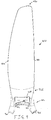
- a single fan blade (50) is shown plan form in FIG. 4 having a root end (52), a tip (70), a leading edge (80) and a trailing edge (90).
- Sections A- A, B- B, and C-C are shown in FIG. 4 and correspond to cross-sectional FIGS. 4A, 4B, and 4C , respectively. Sections A- A, B- B, and C- C will be discussed in greater detail below.
- root end (52) of the present embodiment comprises an arcuate cutout (54) configured to permit lens (48) be inserted in a central aperture (56) formed when fan blades (50) are mounted.
- Root end (52) further includes a pair of openings (58) that permit fasteners (32) to extend therethrough to couple fan blade (50) to motor (30) and/or hub (42).
- root end (52) of the present embodiment fan blade (50) comprises a domed sector that corresponds to an approximately 120 degree sector of a dome for the present fan (10) having three fan blades (50).
- the domed sector of root end (52) is substantially flat, or parallel, relative to the plane of rotation for fan blades (50) at or near arcuate cutout (54).
- the domed sector curves upwardly toward motor (30) and/or support (20).
- Root end (52) may of course include an approximately 180 degree, 90 degree, 60 degree, 45 degree and/or any other sector portion of a dome. Of course other root ends (52) will be apparent to one of ordinary skill in the art in view of the teachings herein.
- Fan blade (50) also includes a transition region (60) extending from root end (52), shown best in FIGS. 4 and 6 .
- transition region (60) comprises a first portion (62), an inflection portion (64), and a second portion (66).
- First portion (62) comprises an extension of the domed sector of root end (52) that terminates at inflection portion (64).
- Inflection portion (64) of the present embodiment comprises a quasi-parabolic shaped portion that extends from leading edge (80) to trailing edge (90) and transitions fan blade (50) from the upwardly extending domed shape of first portion to a planar portion.
- Second portion (66) extends from inflection portion (64) and transitions fan blade (50) from the planar inflection portion (64) to the downwardly curved root airfoil profile (100), shown in FIG. 4A .
- a non-dimensional matrix of coordinates in Table 1 below generally describes the surface formed by transition region (60) and airfoil profile (100). It should be understood that the domed sector of root end (52) is omitted from the coordinates in Table 1.
- the Z coordinate corresponds to the vertical height of the point at the transition point from root end (52) (e.g., a height of 0 corresponds to where root end (52) ends and transition region (60) beings)
- the X coordinate corresponds to the longitudinal distance from a central point about which blade (50) rotates
- the Y coordinate corresponds to the chord-wise position, where negative coordinates approach trailing edge (90) and positive coordinates approach leading edge (80).
- transition region (60) and/or other regions of fan blade (50) may be used.
- transition region (60), etc. will be apparent to one of ordinary skill in the art in view of the teachings herein.
- Root airfoil profile (100) comprises a top surface (102), a bottom surface (104), a leading edge (106), and a trailing edge (108).
- Root airfoil profile (100) of the present embodiment comprises a curved airfoil having a substantially constant thickness (1 10) and a substantially constant radius of curvature (120).
- thickness (110) may range from approximately 1 millimeter (0.03937 inches), inclusive, to approximately 5 millimeters (0.19685 inches), inclusive. In the embodiment shown, thickness (110) is approximately 4 millimeters (0.15748 inches) though this is merely one embodiment.
- radius of curvature (120) is measured from a center point (118) and may range from approximately 2 meters (6.56167 feet), inclusive, to approximately 5 meters (16.4042 feet), inclusive. In the embodiment shown, radius of curvature (120) is approximately 3.7 meters (12.1391 feet). Still further values for radius of curvature (120) will be apparent to one of ordinary skill in the art in view of the teachings herein.
- root airfoil profile (100) is defined when radius of curvature (120) is swept through a root angle (122).
- Root angle (122) of the present embodiment is approximately 14 degrees, though it should be understood that this is merely exemplary and other smaller and/or larger root angles (122) will be apparent to one of ordinary skill in the art in view of the teachings herein.
- leading edge (106) and trailing edge (108) comprise rounded surfaces connecting top surface (102) to bottom surface (104), though this is merely optional.
- Leading edge (102) and trailing edge (104) of the present embodiment form rounded surfaces having a radius of curvature substantially equal to thickness (110).
- a substantially constant thickness root airfoil profile (100) is formed.
- FIG. 4B depicts a cross-sectional intermediate airfoil profile (200) taken along section B- B of FIG. 4 at an approximate midpoint between root airfoil profile (100) and tip airfoil profile (300), discussed in greater detail below. It should be understood that while the term intermediate is used, it does not necessarily connote that the shape, size, or values defining intermediate airfoil profile (200) are in between those of root airfoil profile (100) and tip airfoil profile (300).
- Intermediate airfoil profile (200) of the present embodiment comprises a top surface (202), a bottom surface (204), a leading edge (206), and a trailing edge (208),
- Intermediate airfoil profile (200) of the present embodiment is substantially identical to root airfoil profile (100) and has a substantially identical thickness (1 10) and is defined by a substantially identical radius of curvature (120) with the exception that radius of curvature (120) is swept through an intermediate angle (222).
- intermediate angle (222) is approximately 12.5 degrees, though of course other smaller and/or larger intermediate angles (222) will be apparent to one of ordinary skill in the art in view of the teachings herein.
- FIG. 4C shows a cross-sectional tip airfoil profile (300) taken along section C- C of FIG. 4 at an approximate tip (70) of fan blade (50).
- Tip airfoil profile (300) of the present embodiment comprises a top surface (302), a bottom surface (304), a leading edge (306), and a trailing edge (308).
- Tip airfoil profile (300) of the present embodiment is substantially identical to root airfoil profile (100) and has a substantially identical thickness (110) and is defined by a substantially identical radius of curvature (120) with the exception that radius of curvature (120) is swept through a tip angle (322).
- tip angle (322) is approximately 7 degrees, though of course other smaller and/or larger tip angles (322) will be apparent to one of ordinary skill in the art in view of the teachings herein.
- FIG. 5 depicts a composite overlay of the cross-sections of FIGS. 4A-4C .
- root airfoil profile (100), intermediate airfoil profile (200), and tip airfoil profile (300) are substantially identical in shape and thickness with the exception of each being formed by sweeping radius of curvature (120) to various angle (122, 222, 322).
- the tip angle (322) is a minimum value for the angles through which radius of curvature (120) is swept while root angle (122) is a maximum value for fan blade (50).
- tip angle (322) need not necessarily be the minimum value for the angles through which radius of curvature (120) is swept and/or root angle (122) need not necessarily be the maximum value for the angles through which radius of curvature (120) is swept.
- angles (122, 222, 322) may linearly increase in value from tip angle (322) to root angle (122).
- angles (122, 222, 322) may increase in value logarithmically, parabolically, cubically, and/or in any other manner from tip angle (322) to root angle (122).
- fan blade (50) is also configured to have a blade rise angle (98).
- blade rise angle (98) corresponds to the angle formed between the plane in which the fan rotates and the top surface of fan blade (50).
- the absolute height of each fan blade (50) increases from root end (52) to tip (70).
- blade rise angle (98) may be an angle of approximately 0 degrees, inclusive, to approximately 20 degrees, inclusive. More specifically, blade rise angle (98) may be from 2.5 degrees, inclusive, to 5 degrees, inclusive. In the embodiment shown, blade rise angle (98) is approximately 3.8 degrees.
- flaps, slats, extensions, electrical or mechanical actuators, and/or other features may be added to fan blades (50).
- Fan blade (50) of the present embodiment is manufactured from thin sheets of material laminated together.
- fan blade (50) may be constructed by combining individual sheets with adhesive between each layer and forcing the sheets together under pressure in a shaped mold to form fan blade (50) shown in FIGS. 1-6 .
- fan blade (50) may be manufactured using 7 layers of 0.5 millimeter (0.019685 inches) thick bamboo veneer that are compressed together as described above. Of course other thicknesses and/or number of layers may be used. Alternatively, other types of wooden veneer may be used or may be combined with other woods to form composite fan blades (50).
- fan blade (50) may be formed from of a thermoplastic resin that is injected into a mold for fan blade (50) to achieve the desired profile. Further still, fan blade (50) may be formed from a single layer of plastic that is heated and bent or inserted into a mold to form the profile of fan blade (50). In still a further alternative, fan blade (50) may be formed from layers of fiberglass matting or carbon fiber composite materials combined with epoxy resins. In yet another alternative, layers of wood veneer or other materials (e.g., carbon fiber, fiberglass, etc.) may initially be layered within a mold and plastic or another resin may be injected or otherwise added to form fan blade (50). Of course still further constructions for fan blade (50) will be apparent to one of ordinary skill in the art in view of the teachings herein.
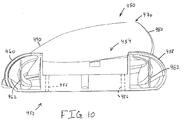
- FIGS. 7-10 depict an alternative fan not part of the claimed subject-matter (400) having a support (410), a motor (420), a hub (430), and a plurality of fan blades (450).
- Support (410) and motor (420) of the present example may be constructed in substantial accordance with support (20) and motor (30) described above.
- Hub (430), shown best in FIG. 8 comprises an annular member disposed about and coupled to motor (420) such that rotation of motor (420) rotates hub (430).
- Hub (430) further includes a plurality of holes (432) to which fasteners (434) may be coupled to substantially fixedly coupled fan blades (450) with hub (430). Accordingly, when motor (420) rotates, fan blades (450) and hub (430) also rotate.
- fan (400) further includes a top cover (412) having a circular center (not shown) and a plurality of rectangular fan extensions (414).
- rectangular fan extensions (414) curve downwardly relative to support (410) and are configured to nest within top recesses (454) formed in fan blades (450), described below, to form a substantially smooth transition between top cover (414) and fan blades (450).
- a circular bottom cover (416) includes a plurality of upwardly projecting reshaped tabs (418) disposed about the circumference of bottom cover (416) and a central lens (419).
- Lens (419) may be constructed in accordance with lens (48) described above.
- Bottom cover (416) is configured to couple to a bottom portion of fan blades (450) via tabs (418) inserting into recesses (not shown) formed in fan blades (450) and then being rotated such that an axial projection from each tab locks into the recesses. Accordingly, when bottom cover (416) is coupled to fan blades (450), a substantially smooth lower surface for fan (400) is formed.
- bottom cover (416) may couple to fan blades (450) through other attachment members, such as screws, bolts, clips, clamps, straps, resilient tabs, etc.
- bottom cover (416) may be directly coupled to motor (420).
- Fan (400) may be further configured in accordance with the teachings of fan (10) described above or in any other manner as will be apparent to one of ordinary skill in the art in view of the teachings herein.
- fan blade (450) of the present example comprises a root end (452), a tip (470), a leading edge (480), and a trailing edge (490).
- Fan blade (450) of the present example comprises airfoil profiles that substantially correspond to airfoil profiles (100, 200, 300) described above.
- fan blade (450) comprises an alternative root end (452) and transition region (466).
- Transition region (466) of the present example comprises a tapered portion of fan blade (450) that transitions from root end (452) to airfoil profiles (100, 200, 300) for fan blade (450).
- Root end (452) of the present example includes a top recess (454) configured to receive a respective extension (414) therein.
- top cover (414) when extensions (414) are nested within respective top recesses (454) a substantially smooth transition is formed from top cover (414) to fan blades (450) for fan (400).
- one or more openings (456) are formed through a lower portion of root end (452) to permit fasteners (434) therethrough to substantially fixedly coupled fan blade (450) to hub (430) described above.
- Root end (452) is further includes a recessed ledge (458) and an outer lip (460) disposed on opposing ends of root end (452).
- recessed ledge (458) corresponds to the side of fan blade (450) with leading edge (480) while outer lip (460) corresponds to the side of fan blade (450) with trailing edge (490). Accordingly, when fan blades (450) are assembled for fan (400), recessed ledge (458) nests with and below outer lip (460) of the fan blade (450) to form a substantially smooth and continuous surface from one fan blade (450) to the next.
- fan blades (450) have root ends (452) with recessed ledges (458) and outer lips (460) disposed approximately 120 degrees from each other such that three fan blades (450) may be combined to form a substantially continuous fan blade structure (as shown in FIG. 7 ).
- other angular relationships may be used as well (e.g., 180 degrees for a dual fan blade (450) assembly, 90 degrees for a four fan blade (450) assembly, 60 degrees for a five fan blade (450) assembly, etc.).
- fasteners may be used to couple corresponding recessed ledges (458) and outer lips (460) together for fan blades (450).
- rubber grommets (not shown) or other vibratory-reducing members may be interposed between corresponding recessed ledges (458) and outer lips (460) to vibrationally isolate fan blades (450) from one another.
- a pair of rib members (462) are provided within root end (452) to reinforce or otherwise provide additional rigidity to root end (452), though these are merely optional. Still further constructions for root end (452) and/or fan blade (450) will be apparent to one of ordinary skill in the art in view of the teachings herein.
- Fan blade (450) of the present example is manufactured by a thermoplastic resin that is injected into a mold for fan blade (450) to achieve the desired profile.
- fan blade (450) may be formed from thin sheets of material laminated together and anchored to a thermoplastic or other material root end (452).
- fan blade (450) may be constructed by combining individual sheets with adhesive between each layer and forcing the sheets together under pressure in a shaped mold to form fan blade (450) shown in FIGS. 9-10 and anchored to root end (452).
- fan blade (450) may be manufactured using 7 layers of 0.5 millimeter (0.019685 inches) thick bamboo veneer that are compressed together as described above. Of course other thicknesses and/or number of layers may be used.
- fan blade (450) may be formed from a single layer of plastic that is heated and bent or inserted into a mold to form the profile of fan blade (450) which is subsequently joined to root end (452).
- fan blade (450) may be formed from layers of fiberglass matting or carbon fiber composite materials combined with epoxy resins.
- layers of wood veneer or other materials e.g., carbon fiber, fiberglass, etc.
- plastic or another resin may be injected or otherwise added to form fan blade (450).
Landscapes
- Engineering & Computer Science (AREA)
- Mechanical Engineering (AREA)
- General Engineering & Computer Science (AREA)
- Structures Of Non-Positive Displacement Pumps (AREA)
Claims (15)
- Ventilatorblatt, welches zur Montage an eine rotierende Ventilatornabe (42) ausgebildet ist, umfassend:ein Flügelende (52), welches zum Ankoppeln an die rotierende Ventilatornabe (42) ausgebildet ist;einen Flügelbereich;eine Vorderkante (80);eine Hinterkante (90); undeine Spitze (70), wobei die Vorderkante (80) und die Hinterkante (90) in der Spitze (70) enden;wobei das Flügelende (52) bei seitlicher Betrachtung in Richtung der Vorderkante (80) einen im Wesentlichen konkaven gewölbten Abschnitt aufweist undwobei ein Übergangbereich (60) sich zwischen dem Flügelende (52) und dem Blattbereich erstreckt, wobei der Übergangbereich (60) ein Profil aufweist, welches das Flügelende in das Blattbereichprofil ändert,dadurch gekennzeichnet,dass ein Profil des Blattbereichs eine im Wesentlichen konvexe obere Fläche undeine untere Fläche aufweist.
- Ventilatorblatt nach Anspruch 1, wobei das Flügelende (52) einen bogenförmigen Ausschnitt (54) aufweist.
- Ventilatorblatt nach Anspruch 2, wobei der gewölbte Abschnitt ausgebildet ist, in einem Bereich zu enden, welcher in einer Position in der Nähe des bogenförmigen Ausschnitts (54) parallel zu einer Rotationsebene des Ventilatorblatts ist.
- Ventilatorblatt nach Anspruch 3, wobei der Übergangsabschnitt einen ersten Abschnitt (62), einen gebogenen Abschnitt (64) und einen zweiten Abschnitt (66) aufweist.
- Ventilatorblatt nach Anspruch 4, wobei der erste Abschnitt (62) eine Verlängerung des konkaven gewölbten Abschnitts des Flügelendes aufweist, wobei die Verlängerung an dem gebogenen Abschnitt (64) endet.
- Ventilatorblatt nach Anspruch 5, wobei der gebogene Abschnitt (64) einen quasiparabolischen Abschnitt aufweist, welcher sich von der Vorderkante (80) zu der Hinterkante (90) erstreckt und das Ventilatorblatt von der Verlängerung des konkaven gewölbten Abschnitts des ersten Abschnitts (62) zu einem ebenen Abschnitt ändert.
- Ventilatorblatt nach Anspruch 6, wobei der zweite Abschnitt (66) sich von dem gebogenen Abschnitt (64) und dem ebenen Abschnitt zu dem Profil des Blattbereichs erstreckt.
- Ventilatorblatt nach Anspruch 7, wobei die obere Fläche des Profils des Blattbereichs Folgendes aufweist: eine erste obere konvexe Biegung nahe dem zweiten Abschnitt (66) des Übergangbereichs und eine zweite obere konvexe Biegung nahe der Spitze (70).
- Ventilatorblatt nach Anspruch 8, wobei die Grundfläche des Profils des Blattbereichs eine erste untere konvexe Biegung nahe dem zweiten Abschnitt (66) des Übergangbereichs und eine zweite untere konvexe Biegung nahe der Spitze (70) aufweist.
- Ventilatorblatt nach Anspruch 9, wobei die obere Fläche des Blattbereichs längs des Blattbereichs von der ersten oberen konvexen Biegung zu der zweiten oberen konvexen Biegung übergeht.
- Ventilatorblatt nach Anspruch 10, wobei die untere Fläche des Blattbereichs längs des Blattbereichs von der ersten unteren konvexen Biegung zu der zweiten unteren konvexen Biegung übergeht.
- Ventilatorblatt nach Anspruch 11, wobei die untere Fläche des Blattbereichs längs des Blattbereichs nach oben steigt.
- Ventilatorblatt nach Anspruch 12, wobei die obere Fläche des Blattbereichs längs des Blattbereichs nach oben steigt.
- Ventilatorblatt nach Anspruch 13, wobei die Vorderkante (80) höher angeordnet ist als die Hinterkante (90).
- Ventilatoranordnung, umfassend:einen Ventilatormotor (30);eine Ventilatornabe (42), wobei die Ventilatornabe (42) an dem Ventilatormotor (50) befestigt ist,gekennzeichnet durchdas Ventilatorblatt nach Anspruch 14, wobei das Ventilatorblatt eines aus einer Vielzahl von ähnlichen an der Ventilatornabe (42) montierten Ventilatorblättern ist.
Applications Claiming Priority (2)
| Application Number | Priority Date | Filing Date | Title |
|---|---|---|---|
| US201261588932P | 2012-01-20 | 2012-01-20 | |
| PCT/US2013/021873 WO2013109711A1 (en) | 2012-01-20 | 2013-01-17 | Thin airfoil ceiling fan blade |
Publications (3)
| Publication Number | Publication Date |
|---|---|
| EP2805061A1 EP2805061A1 (de) | 2014-11-26 |
| EP2805061A4 EP2805061A4 (de) | 2015-10-28 |
| EP2805061B1 true EP2805061B1 (de) | 2018-09-19 |
Family
ID=48797356
Family Applications (1)
| Application Number | Title | Priority Date | Filing Date |
|---|---|---|---|
| EP13737994.7A Not-in-force EP2805061B1 (de) | 2012-01-20 | 2013-01-17 | Deckenlüfterschaufel für eine dünne tragfläche |
Country Status (13)
| Country | Link |
|---|---|
| US (1) | US20130189109A1 (de) |
| EP (1) | EP2805061B1 (de) |
| CN (1) | CN104169587A (de) |
| AU (1) | AU2013209789B2 (de) |
| CA (1) | CA2861920C (de) |
| CO (1) | CO7051022A2 (de) |
| ES (1) | ES2700977T3 (de) |
| HK (1) | HK1203223A1 (de) |
| IL (1) | IL233719A (de) |
| IN (1) | IN2014DN06524A (de) |
| MY (1) | MY173536A (de) |
| SG (1) | SG11201404219SA (de) |
| WO (1) | WO2013109711A1 (de) |
Families Citing this family (57)
| Publication number | Priority date | Publication date | Assignee | Title |
|---|---|---|---|---|
| US8842000B2 (en) | 2012-07-17 | 2014-09-23 | 4Front Engineered Solutions, Inc. | Fire control systems |
| USD716436S1 (en) * | 2013-11-05 | 2014-10-28 | Quorum International, Inc. | Combined ceiling fan and light kit |
| TWM478749U (zh) * | 2014-01-16 | 2014-05-21 | Yih Jen Ind Corp | 具遮翼式葉片的吊扇 |
| US9810227B2 (en) | 2014-01-16 | 2017-11-07 | Minka Lighting, Inc. | Ceiling fan |
| US9874214B2 (en) | 2014-01-28 | 2018-01-23 | 4Front Engineered Solutions, Inc. | Fan with fan blade mounting structure |
| MX381690B (es) | 2014-05-05 | 2025-03-13 | Horton Inc | Ventilador de material compuesto. |
| USD741470S1 (en) * | 2014-06-09 | 2015-10-20 | Youngo Limited | Ceiling fan blade |
| US11085455B1 (en) * | 2014-08-11 | 2021-08-10 | Delta T, Llc | System for regulating airflow associated with product for sale |
| CN105889130A (zh) * | 2014-09-19 | 2016-08-24 | 重庆海光玻璃钢制品有限公司 | 2500m防霜机后风向叶片 |
| USD762296S1 (en) * | 2015-01-12 | 2016-07-26 | Hunter Fan Company | Ceiling fan |
| US9726192B2 (en) | 2015-03-31 | 2017-08-08 | Assa Abloy Entrance Systems Ab | Fan blades and associated blade tips |
| US9897095B2 (en) * | 2015-05-01 | 2018-02-20 | Hunter Fan Company | Ceiling fan kit and method of mounting |
| USD770027S1 (en) | 2015-06-30 | 2016-10-25 | Delta T Corporation | Fan |
| USD797917S1 (en) | 2015-08-17 | 2017-09-19 | Delta T Corporation | Fan with light |
| MX2018007240A (es) | 2015-12-14 | 2018-08-01 | Hunter Fan Co | Ventilador de techo. |
| US11674526B2 (en) | 2016-01-22 | 2023-06-13 | Hunter Fan Company | Ceiling fan having a dual redundant motor mounting assembly |
| USD847969S1 (en) | 2016-01-04 | 2019-05-07 | Delta T, Llc | Fan canopy |
| USD782644S1 (en) * | 2016-02-06 | 2017-03-28 | Youngo Limited | Ceiling fan |
| USD783146S1 (en) * | 2016-02-06 | 2017-04-04 | Youngo Limited | Ceiling fan blade |
| USD795413S1 (en) * | 2016-05-06 | 2017-08-22 | Youngo Limited | Ceiling fan |
| GB2551719A (en) * | 2016-06-27 | 2018-01-03 | Truflo Air Movement Ltd | Improvements in and relating to a fan assembly |
| CN109964042A (zh) * | 2016-09-02 | 2019-07-02 | Usha国际有限公司 | 吊式风扇 |
| WO2018175359A1 (en) | 2017-03-20 | 2018-09-27 | Shop Vac Corporation | Axial fan having housing formed by connectable pieces and including air guide ribs and an internal ramp |
| CN108757567A (zh) * | 2018-05-22 | 2018-11-06 | 张健祥 | 一种新型风扇扇叶片及其制作方法 |
| WO2019240360A1 (ko) * | 2018-06-12 | 2019-12-19 | 엘지전자 주식회사 | 천장 팬 및 그 조립방법 |
| KR102141435B1 (ko) | 2018-06-12 | 2020-08-05 | 엘지전자 주식회사 | 천장 팬 및 그 조립방법 |
| USD905227S1 (en) | 2018-07-10 | 2020-12-15 | Hunter Fan Company | Ceiling fan blade |
| USD906511S1 (en) | 2018-07-10 | 2020-12-29 | Hunter Fan Company | Ceiling fan blade |
| USD905226S1 (en) | 2018-07-10 | 2020-12-15 | Hunter Fan Company | Ceiling fan blade |
| US11111930B2 (en) * | 2018-07-10 | 2021-09-07 | Hunter Fan Company | Ceiling fan blade |
| USD880684S1 (en) | 2018-07-10 | 2020-04-07 | Hunter Fan Company | Ceiling fan blade |
| USD903091S1 (en) | 2018-07-10 | 2020-11-24 | Hunter Fan Company | Ceiling fan blade |
| USD980408S1 (en) | 2018-07-10 | 2023-03-07 | Hunter Fan Company | Ceiling fan blade |
| USD902377S1 (en) | 2018-07-10 | 2020-11-17 | Hunter Fan Company | Ceiling fan blade |
| USD957617S1 (en) | 2018-07-10 | 2022-07-12 | Hunter Fan Company | Ceiling fan blade |
| USD903092S1 (en) | 2018-07-10 | 2020-11-24 | Hunter Fan Company | Ceiling fan blade |
| USD880683S1 (en) | 2018-07-10 | 2020-04-07 | Hunter Fan Company | Ceiling fan blade |
| USD957618S1 (en) | 2018-07-10 | 2022-07-12 | Hunter Fan Compnay | Ceiling fan blade |
| USD880682S1 (en) | 2018-07-10 | 2020-04-07 | Hunter Fan Company | Ceiling fan blade |
| USD957619S1 (en) | 2018-07-10 | 2022-07-12 | Hunter Fan Company | Ceiling fan blade |
| USD905845S1 (en) | 2018-07-10 | 2020-12-22 | Hunter Fan Company | Ceiling fan blade |
| USD880680S1 (en) | 2018-07-10 | 2020-04-07 | Hunter Fan Company | Ceiling fan blade |
| USD880681S1 (en) | 2018-07-10 | 2020-04-07 | Hunter Fan Company | Ceiling fan blade |
| USD936812S1 (en) * | 2018-09-28 | 2021-11-23 | Kichler Lighting Llc | Ceiling fan |
| USD947355S1 (en) * | 2019-05-27 | 2022-03-29 | Hunter Pacific International Pty Ltd. | Ceiling fan |
| USD947354S1 (en) * | 2019-05-27 | 2022-03-29 | Hunter Pacific International Pty Ltd. | Ceiling fan |
| CA198763S (en) * | 2020-04-28 | 2022-07-07 | Gd Midea Env Appliances Mfg Co Ltd | Ceiling fan |
| IT202000020488A1 (it) * | 2020-08-26 | 2022-02-26 | Motordesign Modena S R L | Pala per ventilatori da ambiente e relativo ventilatore |
| USD972114S1 (en) * | 2020-11-19 | 2022-12-06 | Beacon Lighting International Limited | Ceiling fan |
| USD972115S1 (en) * | 2020-11-20 | 2022-12-06 | Zhongshan Glorylux Technology And Electrical Appliance Co., Ltd. | Ceiling fan |
| USD1010095S1 (en) * | 2020-12-22 | 2024-01-02 | Guangdong Shunde Hongfeng Electric & Lighting Appliance Co., Ltd | Combined ceiling fan and light |
| USD1048355S1 (en) | 2022-02-24 | 2024-10-22 | Hunter Fan Company | Ceiling fan |
| CN115479036A (zh) * | 2022-09-02 | 2022-12-16 | 新盛世机电制品(中山)有限公司 | 一种静音且大风量的扇叶 |
| USD1117715S1 (en) * | 2022-09-29 | 2026-03-10 | Atomberg Technologies Pvt Ltd | Ceiling fan |
| CN115717611B (zh) * | 2022-09-30 | 2025-11-21 | 欧普照明股份有限公司 | 扇叶、风扇及风扇灯 |
| EP4596893A1 (de) * | 2022-09-30 | 2025-08-06 | Suzhou Opple Lighting Co., Ltd. | Gebläseschaufel, gebläse und gebläselampe |
| USD1120284S1 (en) * | 2024-09-16 | 2026-03-24 | Hunter Fan Company | Ceiling fan |
Citations (1)
| Publication number | Priority date | Publication date | Assignee | Title |
|---|---|---|---|---|
| USD612476S1 (en) * | 2009-03-17 | 2010-03-23 | Haiku Design SDN. BHD. | Fan |
Family Cites Families (32)
| Publication number | Priority date | Publication date | Assignee | Title |
|---|---|---|---|---|
| CN2120211U (zh) * | 1992-03-07 | 1992-10-28 | 虞志平 | 1~1.4米吊扇塑料风叶片 |
| US5554006A (en) * | 1995-08-03 | 1996-09-10 | Liao; Hsien-Chin | Ceiling fan blade configuration having a concave blade periphery |
| US5669760A (en) * | 1996-07-11 | 1997-09-23 | Chen; Jung-San | Ceiling fan with integral blade and neck |
| US5967754A (en) * | 1997-12-24 | 1999-10-19 | Aloha Housewares Co., Ltd. | One-piece ceiling fan arm and blade unit |
| US6039541A (en) | 1998-04-07 | 2000-03-21 | University Of Central Florida | High efficiency ceiling fan |
| US6659721B1 (en) * | 1998-04-07 | 2003-12-09 | University Of Central Florida | High efficiency ceiling fan blades |
| US6244821B1 (en) | 1999-02-19 | 2001-06-12 | Mechanization Systems Company, Inc. | Low speed cooling fan |
| US6939108B2 (en) | 2003-01-06 | 2005-09-06 | Mechanization Systems Company, Inc. | Cooling fan with reinforced blade |
| US7284960B2 (en) | 2004-07-21 | 2007-10-23 | Delta T Corporation | Fan blades |
| US8079823B2 (en) | 2004-07-21 | 2011-12-20 | Delta T Corporation | Fan blades |
| US7252478B2 (en) | 2004-07-21 | 2007-08-07 | Delta T Corporation | Fan blade modifications |
| US7934907B2 (en) | 2004-07-21 | 2011-05-03 | Delta T Corporation | Cuffed fan blade modifications |
| USD515196S1 (en) * | 2004-10-22 | 2006-02-14 | Luigi Fernando Milone | Ceiling fan |
| US7384242B2 (en) * | 2005-06-17 | 2008-06-10 | Chen Shih Ming | Impeller blade and fan |
| US20070009364A1 (en) * | 2005-07-08 | 2007-01-11 | Mao-Lin Huang | Blade for ceiling fan |
| DE202005019872U1 (de) * | 2005-12-20 | 2006-07-27 | Canova, Vincenzo | Ventilatorgehäuse |
| EP2118494B1 (de) | 2007-03-01 | 2019-05-01 | Delta T, LLC | Schaufelerweiterung für ventilatorschaufel |
| US8152453B2 (en) | 2007-09-17 | 2012-04-10 | Delta T Corporation | Ceiling fan with angled mounting |
| US8147204B2 (en) | 2007-09-26 | 2012-04-03 | Delta T Corporation | Aerodynamic interface component for fan blade |
| ES2620822T3 (es) | 2007-10-10 | 2017-06-29 | Delta T Corporation | Ventilador de techo con tubo estacionario concéntrico y características de parada |
| US8672649B2 (en) | 2007-10-10 | 2014-03-18 | Delta T Corporation | Ceiling fan system with brushless motor |
| US8123479B2 (en) | 2007-12-19 | 2012-02-28 | Delta T Corporation | Method to minimize oscillation in ceiling fans |
| EP2250452B1 (de) | 2008-02-04 | 2019-05-15 | Delta T, LLC | Automatisches steuersystem für deckenventilator auf der basis von temperaturdifferenzen und feuchtigkeit |
| USD587799S1 (en) | 2008-08-15 | 2009-03-03 | Delta T Corporation | Winglet for a fan blade |
| US8770949B2 (en) * | 2008-09-04 | 2014-07-08 | Delta T Corporation | Ceiling fan |
| USD607988S1 (en) | 2009-04-29 | 2010-01-12 | Delta T Corporation | Ceiling fan |
| AU2010246122B2 (en) | 2009-05-04 | 2015-06-18 | Aspen Motion Technologies, Inc | Ceiling fan with variable blade pitch and variable speed control |
| JP5917400B2 (ja) | 2009-10-02 | 2016-05-11 | デルタ ティー コーポレーション | ファンブレード用のエアフェンス |
| USD641075S1 (en) | 2010-03-05 | 2011-07-05 | Delta T Corporation | Fan with ground support and winglets |
| USD635237S1 (en) | 2010-03-05 | 2011-03-29 | Delta T Corporation | Fan with ground support |
| SG184218A1 (en) | 2010-04-22 | 2012-11-29 | Delta T Corp | Fan blade retention system |
| US8430541B2 (en) * | 2011-06-13 | 2013-04-30 | Ching-Yang Ko | Ceiling fan with illumination mechanism |
-
2013
- 2013-01-17 HK HK15103697.3A patent/HK1203223A1/xx unknown
- 2013-01-17 WO PCT/US2013/021873 patent/WO2013109711A1/en not_active Ceased
- 2013-01-17 SG SG11201404219SA patent/SG11201404219SA/en unknown
- 2013-01-17 AU AU2013209789A patent/AU2013209789B2/en not_active Ceased
- 2013-01-17 ES ES13737994T patent/ES2700977T3/es active Active
- 2013-01-17 MY MYPI2014002125A patent/MY173536A/en unknown
- 2013-01-17 EP EP13737994.7A patent/EP2805061B1/de not_active Not-in-force
- 2013-01-17 CN CN201380014722.6A patent/CN104169587A/zh active Pending
- 2013-01-17 US US13/743,456 patent/US20130189109A1/en not_active Abandoned
- 2013-01-17 CA CA2861920A patent/CA2861920C/en active Active
-
2014
- 2014-07-20 IL IL233719A patent/IL233719A/en active IP Right Grant
- 2014-08-04 IN IN6524DEN2014 patent/IN2014DN06524A/en unknown
- 2014-08-20 CO CO14182399A patent/CO7051022A2/es unknown
Patent Citations (1)
| Publication number | Priority date | Publication date | Assignee | Title |
|---|---|---|---|---|
| USD612476S1 (en) * | 2009-03-17 | 2010-03-23 | Haiku Design SDN. BHD. | Fan |
Also Published As
| Publication number | Publication date |
|---|---|
| US20130189109A1 (en) | 2013-07-25 |
| IN2014DN06524A (de) | 2015-06-12 |
| CO7051022A2 (es) | 2014-09-10 |
| CN104169587A (zh) | 2014-11-26 |
| WO2013109711A1 (en) | 2013-07-25 |
| EP2805061A4 (de) | 2015-10-28 |
| ES2700977T3 (es) | 2019-02-20 |
| SG11201404219SA (en) | 2014-08-28 |
| EP2805061A1 (de) | 2014-11-26 |
| CA2861920A1 (en) | 2013-07-25 |
| HK1203223A1 (en) | 2015-10-23 |
| IL233719A0 (en) | 2014-09-30 |
| AU2013209789A1 (en) | 2014-08-21 |
| IL233719A (en) | 2016-08-31 |
| MY173536A (en) | 2020-02-03 |
| AU2013209789B2 (en) | 2017-06-29 |
| CA2861920C (en) | 2022-10-18 |
Similar Documents
| Publication | Publication Date | Title |
|---|---|---|
| EP2805061B1 (de) | Deckenlüfterschaufel für eine dünne tragfläche | |
| US8821126B2 (en) | Angled airfoil extension for fan blade | |
| CN106953466B (zh) | 风扇轮以及电动机 | |
| US8147204B2 (en) | Aerodynamic interface component for fan blade | |
| CN201391482Y (zh) | 螺旋桨式风扇、流体输送装置及成型模具 | |
| CN102549237B (zh) | 用于风扇叶片的导流栅及具有该导流栅的风扇 | |
| KR102398254B1 (ko) | 임펠러 및 이를 구비한 냉각 팬 | |
| US10087912B2 (en) | Vortex generator for a rotor blade | |
| CA2918998A1 (en) | Fan blades and associated blade tips | |
| CN102374178A (zh) | 风扇 | |
| AU2019202432B2 (en) | A blade adapter and ceiling fan including the same | |
| BR102014024689A2 (pt) | conjunto de ventilação | |
| EP2644902B1 (de) | Axialstromventilator | |
| US20030103846A1 (en) | Propeller fan, propeller molding mold, and fluid feeding device | |
| KR101320805B1 (ko) | 팬 블레이드와 그 개조체 | |
| EP3194136A1 (de) | Windturbinenschaufel mit angepasster sehnenlänge | |
| CN121152927A (zh) | 用于轴流式风扇的风扇叶片 | |
| ES2962630T3 (es) | Un método de fabricación de cuerpo de pala de aerogenerador | |
| US11873818B2 (en) | Ceiling fan | |
| CN109469644B (zh) | 轴流风叶 | |
| CN201310490Y (zh) | 一种电子散热风扇 | |
| CN111601967A (zh) | 风能设备和用于风能设备的转子叶片 | |
| KR101223073B1 (ko) | 풍력 발전기용 익형 블레이드 및 이를 구비한 풍차 | |
| KR101384994B1 (ko) | 풍력 발전기 | |
| AU2012202126B2 (en) | Angled air foil extension for fan blade |
Legal Events
| Date | Code | Title | Description |
|---|---|---|---|
| PUAI | Public reference made under article 153(3) epc to a published international application that has entered the european phase |
Free format text: ORIGINAL CODE: 0009012 |
|
| 17P | Request for examination filed |
Effective date: 20140819 |
|
| AK | Designated contracting states |
Kind code of ref document: A1 Designated state(s): AL AT BE BG CH CY CZ DE DK EE ES FI FR GB GR HR HU IE IS IT LI LT LU LV MC MK MT NL NO PL PT RO RS SE SI SK SM TR |
|
| DAX | Request for extension of the european patent (deleted) | ||
| RA4 | Supplementary search report drawn up and despatched (corrected) |
Effective date: 20150925 |
|
| RIC1 | Information provided on ipc code assigned before grant |
Ipc: F04D 29/38 20060101AFI20150921BHEP Ipc: F04D 29/34 20060101ALI20150921BHEP Ipc: B64C 11/16 20060101ALI20150921BHEP |
|
| STAA | Information on the status of an ep patent application or granted ep patent |
Free format text: STATUS: EXAMINATION IS IN PROGRESS |
|
| 17Q | First examination report despatched |
Effective date: 20170901 |
|
| GRAP | Despatch of communication of intention to grant a patent |
Free format text: ORIGINAL CODE: EPIDOSNIGR1 |
|
| STAA | Information on the status of an ep patent application or granted ep patent |
Free format text: STATUS: GRANT OF PATENT IS INTENDED |
|
| INTG | Intention to grant announced |
Effective date: 20180328 |
|
| GRAS | Grant fee paid |
Free format text: ORIGINAL CODE: EPIDOSNIGR3 |
|
| GRAA | (expected) grant |
Free format text: ORIGINAL CODE: 0009210 |
|
| STAA | Information on the status of an ep patent application or granted ep patent |
Free format text: STATUS: THE PATENT HAS BEEN GRANTED |
|
| RAP1 | Party data changed (applicant data changed or rights of an application transferred) |
Owner name: DELTA T, LLC |
|
| AK | Designated contracting states |
Kind code of ref document: B1 Designated state(s): AL AT BE BG CH CY CZ DE DK EE ES FI FR GB GR HR HU IE IS IT LI LT LU LV MC MK MT NL NO PL PT RO RS SE SI SK SM TR |
|
| REG | Reference to a national code |
Ref country code: GB Ref legal event code: FG4D |
|
| REG | Reference to a national code |
Ref country code: CH Ref legal event code: EP |
|
| REG | Reference to a national code |
Ref country code: AT Ref legal event code: REF Ref document number: 1043580 Country of ref document: AT Kind code of ref document: T Effective date: 20181015 |
|
| REG | Reference to a national code |
Ref country code: IE Ref legal event code: FG4D |
|
| REG | Reference to a national code |
Ref country code: DE Ref legal event code: R096 Ref document number: 602013043881 Country of ref document: DE |
|
| REG | Reference to a national code |
Ref country code: NL Ref legal event code: MP Effective date: 20180919 |
|
| PG25 | Lapsed in a contracting state [announced via postgrant information from national office to epo] |
Ref country code: FI Free format text: LAPSE BECAUSE OF FAILURE TO SUBMIT A TRANSLATION OF THE DESCRIPTION OR TO PAY THE FEE WITHIN THE PRESCRIBED TIME-LIMIT Effective date: 20180919 Ref country code: GR Free format text: LAPSE BECAUSE OF FAILURE TO SUBMIT A TRANSLATION OF THE DESCRIPTION OR TO PAY THE FEE WITHIN THE PRESCRIBED TIME-LIMIT Effective date: 20181220 Ref country code: LT Free format text: LAPSE BECAUSE OF FAILURE TO SUBMIT A TRANSLATION OF THE DESCRIPTION OR TO PAY THE FEE WITHIN THE PRESCRIBED TIME-LIMIT Effective date: 20180919 Ref country code: SE Free format text: LAPSE BECAUSE OF FAILURE TO SUBMIT A TRANSLATION OF THE DESCRIPTION OR TO PAY THE FEE WITHIN THE PRESCRIBED TIME-LIMIT Effective date: 20180919 Ref country code: NO Free format text: LAPSE BECAUSE OF FAILURE TO SUBMIT A TRANSLATION OF THE DESCRIPTION OR TO PAY THE FEE WITHIN THE PRESCRIBED TIME-LIMIT Effective date: 20181219 Ref country code: BG Free format text: LAPSE BECAUSE OF FAILURE TO SUBMIT A TRANSLATION OF THE DESCRIPTION OR TO PAY THE FEE WITHIN THE PRESCRIBED TIME-LIMIT Effective date: 20181219 Ref country code: RS Free format text: LAPSE BECAUSE OF FAILURE TO SUBMIT A TRANSLATION OF THE DESCRIPTION OR TO PAY THE FEE WITHIN THE PRESCRIBED TIME-LIMIT Effective date: 20180919 |
|
| REG | Reference to a national code |
Ref country code: LT Ref legal event code: MG4D |
|
| REG | Reference to a national code |
Ref country code: ES Ref legal event code: FG2A Ref document number: 2700977 Country of ref document: ES Kind code of ref document: T3 Effective date: 20190220 |
|
| PG25 | Lapsed in a contracting state [announced via postgrant information from national office to epo] |
Ref country code: HR Free format text: LAPSE BECAUSE OF FAILURE TO SUBMIT A TRANSLATION OF THE DESCRIPTION OR TO PAY THE FEE WITHIN THE PRESCRIBED TIME-LIMIT Effective date: 20180919 Ref country code: LV Free format text: LAPSE BECAUSE OF FAILURE TO SUBMIT A TRANSLATION OF THE DESCRIPTION OR TO PAY THE FEE WITHIN THE PRESCRIBED TIME-LIMIT Effective date: 20180919 Ref country code: AL Free format text: LAPSE BECAUSE OF FAILURE TO SUBMIT A TRANSLATION OF THE DESCRIPTION OR TO PAY THE FEE WITHIN THE PRESCRIBED TIME-LIMIT Effective date: 20180919 |
|
| REG | Reference to a national code |
Ref country code: AT Ref legal event code: MK05 Ref document number: 1043580 Country of ref document: AT Kind code of ref document: T Effective date: 20180919 |
|
| PG25 | Lapsed in a contracting state [announced via postgrant information from national office to epo] |
Ref country code: NL Free format text: LAPSE BECAUSE OF FAILURE TO SUBMIT A TRANSLATION OF THE DESCRIPTION OR TO PAY THE FEE WITHIN THE PRESCRIBED TIME-LIMIT Effective date: 20180919 Ref country code: RO Free format text: LAPSE BECAUSE OF FAILURE TO SUBMIT A TRANSLATION OF THE DESCRIPTION OR TO PAY THE FEE WITHIN THE PRESCRIBED TIME-LIMIT Effective date: 20180919 Ref country code: CZ Free format text: LAPSE BECAUSE OF FAILURE TO SUBMIT A TRANSLATION OF THE DESCRIPTION OR TO PAY THE FEE WITHIN THE PRESCRIBED TIME-LIMIT Effective date: 20180919 Ref country code: AT Free format text: LAPSE BECAUSE OF FAILURE TO SUBMIT A TRANSLATION OF THE DESCRIPTION OR TO PAY THE FEE WITHIN THE PRESCRIBED TIME-LIMIT Effective date: 20180919 Ref country code: EE Free format text: LAPSE BECAUSE OF FAILURE TO SUBMIT A TRANSLATION OF THE DESCRIPTION OR TO PAY THE FEE WITHIN THE PRESCRIBED TIME-LIMIT Effective date: 20180919 Ref country code: PL Free format text: LAPSE BECAUSE OF FAILURE TO SUBMIT A TRANSLATION OF THE DESCRIPTION OR TO PAY THE FEE WITHIN THE PRESCRIBED TIME-LIMIT Effective date: 20180919 Ref country code: IS Free format text: LAPSE BECAUSE OF FAILURE TO SUBMIT A TRANSLATION OF THE DESCRIPTION OR TO PAY THE FEE WITHIN THE PRESCRIBED TIME-LIMIT Effective date: 20190119 |
|
| PG25 | Lapsed in a contracting state [announced via postgrant information from national office to epo] |
Ref country code: PT Free format text: LAPSE BECAUSE OF FAILURE TO SUBMIT A TRANSLATION OF THE DESCRIPTION OR TO PAY THE FEE WITHIN THE PRESCRIBED TIME-LIMIT Effective date: 20190119 Ref country code: SK Free format text: LAPSE BECAUSE OF FAILURE TO SUBMIT A TRANSLATION OF THE DESCRIPTION OR TO PAY THE FEE WITHIN THE PRESCRIBED TIME-LIMIT Effective date: 20180919 Ref country code: SM Free format text: LAPSE BECAUSE OF FAILURE TO SUBMIT A TRANSLATION OF THE DESCRIPTION OR TO PAY THE FEE WITHIN THE PRESCRIBED TIME-LIMIT Effective date: 20180919 |
|
| REG | Reference to a national code |
Ref country code: DE Ref legal event code: R097 Ref document number: 602013043881 Country of ref document: DE |
|
| PLBE | No opposition filed within time limit |
Free format text: ORIGINAL CODE: 0009261 |
|
| STAA | Information on the status of an ep patent application or granted ep patent |
Free format text: STATUS: NO OPPOSITION FILED WITHIN TIME LIMIT |
|
| PG25 | Lapsed in a contracting state [announced via postgrant information from national office to epo] |
Ref country code: DK Free format text: LAPSE BECAUSE OF FAILURE TO SUBMIT A TRANSLATION OF THE DESCRIPTION OR TO PAY THE FEE WITHIN THE PRESCRIBED TIME-LIMIT Effective date: 20180919 |
|
| 26N | No opposition filed |
Effective date: 20190620 |
|
| PG25 | Lapsed in a contracting state [announced via postgrant information from national office to epo] |
Ref country code: MC Free format text: LAPSE BECAUSE OF FAILURE TO SUBMIT A TRANSLATION OF THE DESCRIPTION OR TO PAY THE FEE WITHIN THE PRESCRIBED TIME-LIMIT Effective date: 20180919 |
|
| REG | Reference to a national code |
Ref country code: CH Ref legal event code: PL |
|
| PG25 | Lapsed in a contracting state [announced via postgrant information from national office to epo] |
Ref country code: LU Free format text: LAPSE BECAUSE OF NON-PAYMENT OF DUE FEES Effective date: 20190117 |
|
| REG | Reference to a national code |
Ref country code: BE Ref legal event code: MM Effective date: 20190131 |
|
| REG | Reference to a national code |
Ref country code: IE Ref legal event code: MM4A |
|
| PG25 | Lapsed in a contracting state [announced via postgrant information from national office to epo] |
Ref country code: SI Free format text: LAPSE BECAUSE OF FAILURE TO SUBMIT A TRANSLATION OF THE DESCRIPTION OR TO PAY THE FEE WITHIN THE PRESCRIBED TIME-LIMIT Effective date: 20180919 |
|
| PG25 | Lapsed in a contracting state [announced via postgrant information from national office to epo] |
Ref country code: BE Free format text: LAPSE BECAUSE OF NON-PAYMENT OF DUE FEES Effective date: 20190131 |
|
| PG25 | Lapsed in a contracting state [announced via postgrant information from national office to epo] |
Ref country code: CH Free format text: LAPSE BECAUSE OF NON-PAYMENT OF DUE FEES Effective date: 20190131 Ref country code: LI Free format text: LAPSE BECAUSE OF NON-PAYMENT OF DUE FEES Effective date: 20190131 |
|
| PG25 | Lapsed in a contracting state [announced via postgrant information from national office to epo] |
Ref country code: IE Free format text: LAPSE BECAUSE OF NON-PAYMENT OF DUE FEES Effective date: 20190117 |
|
| PG25 | Lapsed in a contracting state [announced via postgrant information from national office to epo] |
Ref country code: TR Free format text: LAPSE BECAUSE OF FAILURE TO SUBMIT A TRANSLATION OF THE DESCRIPTION OR TO PAY THE FEE WITHIN THE PRESCRIBED TIME-LIMIT Effective date: 20180919 |
|
| PG25 | Lapsed in a contracting state [announced via postgrant information from national office to epo] |
Ref country code: MT Free format text: LAPSE BECAUSE OF NON-PAYMENT OF DUE FEES Effective date: 20190117 |
|
| PG25 | Lapsed in a contracting state [announced via postgrant information from national office to epo] |
Ref country code: CY Free format text: LAPSE BECAUSE OF FAILURE TO SUBMIT A TRANSLATION OF THE DESCRIPTION OR TO PAY THE FEE WITHIN THE PRESCRIBED TIME-LIMIT Effective date: 20180919 |
|
| PG25 | Lapsed in a contracting state [announced via postgrant information from national office to epo] |
Ref country code: HU Free format text: LAPSE BECAUSE OF FAILURE TO SUBMIT A TRANSLATION OF THE DESCRIPTION OR TO PAY THE FEE WITHIN THE PRESCRIBED TIME-LIMIT; INVALID AB INITIO Effective date: 20130117 |
|
| PGFP | Annual fee paid to national office [announced via postgrant information from national office to epo] |
Ref country code: DE Payment date: 20220127 Year of fee payment: 10 Ref country code: GB Payment date: 20220127 Year of fee payment: 10 |
|
| PGFP | Annual fee paid to national office [announced via postgrant information from national office to epo] |
Ref country code: IT Payment date: 20220119 Year of fee payment: 10 Ref country code: FR Payment date: 20220125 Year of fee payment: 10 Ref country code: ES Payment date: 20220201 Year of fee payment: 10 |
|
| PG25 | Lapsed in a contracting state [announced via postgrant information from national office to epo] |
Ref country code: MK Free format text: LAPSE BECAUSE OF FAILURE TO SUBMIT A TRANSLATION OF THE DESCRIPTION OR TO PAY THE FEE WITHIN THE PRESCRIBED TIME-LIMIT Effective date: 20180919 |
|
| REG | Reference to a national code |
Ref country code: DE Ref legal event code: R119 Ref document number: 602013043881 Country of ref document: DE |
|
| GBPC | Gb: european patent ceased through non-payment of renewal fee |
Effective date: 20230117 |
|
| PG25 | Lapsed in a contracting state [announced via postgrant information from national office to epo] |
Ref country code: GB Free format text: LAPSE BECAUSE OF NON-PAYMENT OF DUE FEES Effective date: 20230117 Ref country code: DE Free format text: LAPSE BECAUSE OF NON-PAYMENT OF DUE FEES Effective date: 20230801 |
|
| PG25 | Lapsed in a contracting state [announced via postgrant information from national office to epo] |
Ref country code: FR Free format text: LAPSE BECAUSE OF NON-PAYMENT OF DUE FEES Effective date: 20230131 |
|
| PG25 | Lapsed in a contracting state [announced via postgrant information from national office to epo] |
Ref country code: IT Free format text: LAPSE BECAUSE OF NON-PAYMENT OF DUE FEES Effective date: 20230117 |
|
| REG | Reference to a national code |
Ref country code: ES Ref legal event code: FD2A Effective date: 20240401 |
|
| PG25 | Lapsed in a contracting state [announced via postgrant information from national office to epo] |
Ref country code: ES Free format text: LAPSE BECAUSE OF NON-PAYMENT OF DUE FEES Effective date: 20230118 |
|
| PG25 | Lapsed in a contracting state [announced via postgrant information from national office to epo] |
Ref country code: ES Free format text: LAPSE BECAUSE OF NON-PAYMENT OF DUE FEES Effective date: 20230118 |