EP2805344B1 - Dispositif de détection pour dispositifs de commutation à basse, moyenne ou haute tension - Google Patents
Dispositif de détection pour dispositifs de commutation à basse, moyenne ou haute tension Download PDFInfo
- Publication number
- EP2805344B1 EP2805344B1 EP13701364.5A EP13701364A EP2805344B1 EP 2805344 B1 EP2805344 B1 EP 2805344B1 EP 13701364 A EP13701364 A EP 13701364A EP 2805344 B1 EP2805344 B1 EP 2805344B1
- Authority
- EP
- European Patent Office
- Prior art keywords
- sensing
- voltage
- sensing device
- current
- sensing part
- Prior art date
- Legal status (The legal status is an assumption and is not a legal conclusion. Google has not performed a legal analysis and makes no representation as to the accuracy of the status listed.)
- Active
Links
Images


Classifications
-
- G—PHYSICS
- G01—MEASURING; TESTING
- G01R—MEASURING ELECTRIC VARIABLES; MEASURING MAGNETIC VARIABLES
- G01R19/00—Arrangements for measuring currents or voltages or for indicating presence or sign thereof
-
- G—PHYSICS
- G01—MEASURING; TESTING
- G01R—MEASURING ELECTRIC VARIABLES; MEASURING MAGNETIC VARIABLES
- G01R15/00—Details of measuring arrangements of the types provided for in groups G01R17/00 - G01R29/00, G01R33/00 - G01R33/26 or G01R35/00
- G01R15/14—Adaptations providing voltage or current isolation, e.g. for high-voltage or high-current networks
- G01R15/142—Arrangements for simultaneous measurements of several parameters employing techniques covered by groups G01R15/14 - G01R15/26
-
- G—PHYSICS
- G01—MEASURING; TESTING
- G01R—MEASURING ELECTRIC VARIABLES; MEASURING MAGNETIC VARIABLES
- G01R19/00—Arrangements for measuring currents or voltages or for indicating presence or sign thereof
- G01R19/0084—Measuring voltage only
-
- G—PHYSICS
- G01—MEASURING; TESTING
- G01R—MEASURING ELECTRIC VARIABLES; MEASURING MAGNETIC VARIABLES
- G01R19/00—Arrangements for measuring currents or voltages or for indicating presence or sign thereof
- G01R19/0092—Measuring current only
-
- H—ELECTRICITY
- H01—ELECTRIC ELEMENTS
- H01H—ELECTRIC SWITCHES; RELAYS; SELECTORS; EMERGENCY PROTECTIVE DEVICES
- H01H33/00—High-tension or heavy-current switches with arc-extinguishing or arc-preventing means
- H01H33/02—Details
- H01H33/027—Integrated apparatus for measuring current or voltage
-
- H—ELECTRICITY
- H01—ELECTRIC ELEMENTS
- H01H—ELECTRIC SWITCHES; RELAYS; SELECTORS; EMERGENCY PROTECTIVE DEVICES
- H01H71/00—Details of the protective switches or relays covered by groups H01H73/00 - H01H83/00
- H01H71/10—Operating or release mechanisms
- H01H71/12—Automatic release mechanisms with or without manual release
- H01H71/123—Automatic release mechanisms with or without manual release using a solid-state trip unit
- H01H71/125—Automatic release mechanisms with or without manual release using a solid-state trip unit characterised by sensing elements, e.g. current transformers
-
- H—ELECTRICITY
- H01—ELECTRIC ELEMENTS
- H01H—ELECTRIC SWITCHES; RELAYS; SELECTORS; EMERGENCY PROTECTIVE DEVICES
- H01H83/00—Protective switches, e.g. circuit-breaking switches, or protective relays operated by abnormal electrical conditions otherwise than solely by excess current
- H01H83/10—Protective switches, e.g. circuit-breaking switches, or protective relays operated by abnormal electrical conditions otherwise than solely by excess current operated by excess voltage, e.g. for lightning protection
-
- H—ELECTRICITY
- H01—ELECTRIC ELEMENTS
- H01H—ELECTRIC SWITCHES; RELAYS; SELECTORS; EMERGENCY PROTECTIVE DEVICES
- H01H83/00—Protective switches, e.g. circuit-breaking switches, or protective relays operated by abnormal electrical conditions otherwise than solely by excess current
- H01H83/12—Protective switches, e.g. circuit-breaking switches, or protective relays operated by abnormal electrical conditions otherwise than solely by excess current operated by voltage falling below a predetermined value, e.g. for no-volt protection
Definitions
- the invention concerns to a voltage and/or current sensing device for low-, medium- or high voltage switching devices connected to an upper and/or a lower terminal of the switching device and the ground potential.
- WO2008/151937A1 relates to a switching pole for a high-voltage network, having a switching unit disposed in the switching pole housing thereof, the switching unit comprising a fixed and movable contact, wherein an input connector on the fixed contact side is connected to an output connector on the movable contact side in an electrically conductive manner in the switched-on position of the switching unit.
- the current and voltage transformer is intended for a metal-encapsulated, gas-insulated high-voltage installation. It has an annular supporting body which can be fixed inside the metal encapsulation and is used for holding a current sensor and a voltage sensor.
- the current sensor, held on the supporting body is constructed as a toroidally wound coil and the voltage sensor, held on the supporting body, is constructed as a hollow-cylindrical measurement electrode.
- the coil and measurement electrode concentrically surround a current conductor of the installation.
- This current and voltage transformer is intended to have small dimensions and is intended to be capable of fitment without problems at any point in the installation.
- the coil is wound in the manner of a Rogowski coil on an annular core of non-ferromagnetic material, of essentially rectangular cross-section when cut in the axial direction, having a small radial dimension in comparison with the radius of the core and with its axial extent, and is arranged in a hollow-cylindrical space in the supporting body, which space is shielded against electric fields and whose boundary wall providing the electrical shielding is connected, after fitment, to the potential of the metal encapsulation.
- the sensing device comprises a first voltage sensing part, second voltage sensing part and a current sensing part arranged in a single housing in a way that output wire from the first voltage sensing part, sensing voltage at an upper terminal of the switching device, is located close to the current sensing part.
- the invention and its scope of protection are defined in appended claim 1, where a sensing device for a low-voltage, medium-voltage or high voltage switching device, for connection to a terminal of such a switching device and to ground potential is defined.
- Embodiments of the invention are defined in the appended dependent claims.
- the invention is, to present a single measuring device that enables to measure voltages on both ends of devices such as circuit breaker or disconnector. Special construction of such device allows combination of two phase-to-ground voltage measurements and current measurement into a single design.
- the second voltage sensing part is located between the current sensing part and lower terminal of the switching device.
- the second voltage sensing part is located in parallel to the current sensing part, and is connected between the lower terminal and the ground potential of the switching device.
- a first advantageous alternative according to the type of voltage sensor is, that at least the first of the voltage sensing parts, located at the upper terminal is applied with, or arranged as resistive divider. This includes also, that both voltage sensing parts can be applied with or arranged as resistive divider.
- current transformer for current sensing part and/or voltage transformer for at least one voltage sensing part are applied.
- the sensing device contains of two voltage sensing parts.
- the sensing device contains one voltage sensing part and one current sensing part.
- the device can be used alternatively.
- First alternative is, that the sensing device is applied for single phase application.
- the device can also be applied for multiple phase application, in that way, that each phase is applied with one independent sensing device.
- the sensing device in the use of the sensing device in switchgears with circuit breaker or vacuum circuit breaker, the sensing device is in the near of a pole part, which contains the vacuum circuit breaker.
- the invention related sensing device is very compact, and so with high practical use, in switchgear arrangements which should be compact.
- the sensing device is positioned in parallel to the circuit breaker or pole part long axis.
- the sensing device has a high practical importance for the use in disconnectors, in order to ensure also security effects.
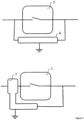
- Fig. 1 shows a double voltage sensing device 6 over switching device 1. It is also possible to implement a current sensing integrated inside of the same device, see bottom part of figure 1 , which shows a double voltage sensing device with current sensing integrated 7.
- Sensing of current and voltage could be realized by different means, e.g. by conventional current and voltage instrument transformers or low-power current and voltage sensors could be used. Biggest advantage and lowest size of such solution could be preferably achieved by low-power sensors.
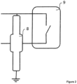
- Preferred design that follow the same idea as in Fig. 1 (bottom) and that is much more size optimized is described in Fig. 2 .
- the switching device is a circuit breaker that has contact arms located above each other. Such concept has less space available between the contact arms and sensing solution could be then fully optimized.
- Both phase-to-ground voltage sensing parts of the device 8 needs to connect one of their end to the line voltage to be sensed and the other one to the ground potential.
- voltage distribution between the contact arms and fully optimized space occupied following design of the sensing device 8, which is a current sensor, integrated with double voltage sensing device, is preferred, see Fig.3 .
- Fig. 3 shows a construction of double voltage sensing device with integrated current sensing
- Fig. 3 shows a sensing device 8 comprising of first voltage sensing device 12, preferably a resistive voltage divider, current sensing device 13, preferably a low-power current sensor and a second voltage sensing device 14, preferably a capacitive voltage divider.
- Line voltage to be sensed is located at upper terminal 10 of the circuit breaker 9 and at lower terminal 11.
- First voltage sensing device 12 has ground connection 15 connected to the grounded shield of current sensing device 13.
- Output wire 16 of the first voltage sensing device 12 is located close to the current sensing device 13, but being insulated from each other. Output from current sensing device 13 is done by means of two output wires 19.
- Main part of a second voltage sensing device 14 is located within a current sensing device 13, but secondary impedance 17 of a second voltage sensing device 14 is located outside.
- Output of a second voltage sensing device 14 is realized by output wire 18. All outputs 16, 18 and 19 from sensing elements are insulated from each other. They might have a separate output wire or cable each, or they all could be also integrated into one output cable.
- One end of both voltage sensing devices 12 and 14 has to be connected to the ground terminal 20.
- the sensing device is electrically shielded, and the shield is connected to the grounding terminal 20 as well.
- Figure 4 shows the compact and near placement of the invention related switching device in parallel to the long axis of a typical medium voltage pole part.
- Figure 5 shows an embodiment which does not form part of the invention.
- Top Part of Figure 5 shows a separate current 2 and voltage 3, 4 sensing devices over the switching device 1.
- Such device could be either single-phase device or the same approach could be applied in case of three-phase device as well. In that case, the same arrangement is done in all three phases.
- FIG. 5 Bottom part of figure 5 shows a Combined current and voltage sensing device 5, which is a combined current and voltage sensing device on one side and single voltage sensing device 4 on the other side of switching device 1.
- FIG. 6 shows a further detailed alternative concerning to the arrangement of the several sensors in the housing 30.
- the second voltage sensing part 14 is located in parallel to the current sensing part 13 and it is connected between the lower terminal 11 and the ground terminal 20 of the switching device.
Landscapes
- Physics & Mathematics (AREA)
- General Physics & Mathematics (AREA)
- Engineering & Computer Science (AREA)
- Power Engineering (AREA)
- Measuring Instrument Details And Bridges, And Automatic Balancing Devices (AREA)
- Gas-Insulated Switchgears (AREA)
- Measurement Of Current Or Voltage (AREA)
- Breakers (AREA)
Claims (11)
- Dispositif de détection pour un dispositif de commutation basse tension, moyenne tension ou haute tension, pour une connexion à une borne d'un tel dispositif de commutation et à un potentiel de terre, le dispositif de commutation comprenant :une première partie de détection de tension (12) ; etune deuxième partie de détection de tension (14) ;une partie de détection de courant (13) étant agencée avec la première partie de détection de tension et la deuxième partie de détection de tension dans un unique boîtier (30) de dispositif de détection commun,une extrémité de la première partie de détection de tension, une extrémité de la deuxième partie de détection de tension et un blindage électrique de la partie de détection de courant (13) étant connectés à une borne de terre (20) ;une sortie (16) de la première partie de détection de tension (12) pour détecter une tension au niveau d'une borne supérieure (10) du dispositif de commutation s'étendant dans le boîtier (30) de dispositif de détection et étant isolée de la partie de détection de courant (13) ;une sortie (18) de la deuxième partie de détection de tension (14) pour détecter une tension au niveau d'une borne inférieure (11) du dispositif de commutation s'étendant dans le boîtier (30) de dispositif de détection ;la sortie (16) de la première partie de détection de tension (12), la sortie (18) de la deuxième partie de détection de tension (14) et une sortie (19) de la partie de détection de courant (13) étant isolées les unes des autres ; etle dispositif de commutation et le dispositif de détection comprenant différents dispositifs, caractérisé en ce que le boîtier (30) de dispositif de détection est séparé d'un boîtier pour le dispositif de commutation.
- Dispositif de détection selon la revendication 1, la deuxième partie de détection de tension étant située entre la partie de détection de courant et une connexion pour une borne inférieure du dispositif de commutation.
- Dispositif de détection selon la revendication 1, la deuxième partie de détection de tension étant située en parallèle de la partie de détection de courant, pour une connexion entre une borne inférieure et un potentiel de terre du dispositif de commutation.
- Dispositif de détection selon l'une quelconque des revendications 1 à 3, au moins la première des parties de détection de tension, située au niveau de la borne supérieure étant un diviseur résistif.
- Dispositif de détection selon la revendication 1, la première partie de détection de tension, située au niveau de la borne supérieure étant munie de, ou agencée en tant qu'un diviseur résistif, et la deuxième partie de détection de tension située au niveau de la borne inférieure étant un diviseur résistif.
- Dispositif de détection selon l'une quelconque des revendications 1 à 5, comprenant :
des technologies de détection de courant et de tension basse puissance en tant que parties de détection de courant et de tension. - Dispositif de détection selon l'une quelconque des revendications 1 à 5, comprenant :
un transformateur de courant pour une partie de détection de courant et/ou un transformateur de tension pour au moins une partie de détection de courant. - Dispositif de détection selon l'une quelconque des revendications 1 à 5, le dispositif de détection étant configuré pour une détection monophasée.
- Dispositif de détection configuré pour une détection triphasée, chaque phase étant munie d'un dispositif de détection indépendant selon la revendication 1.
- Dispositif de détection selon l'une quelconque des revendications 1 à 9, en combinaison avec un appareillage de connexion, avec un disjoncteur ou avec un disjoncteur à vide, le dispositif de détection étant positionné à proximité d'une partie formant poteau qui contient le disjoncteur ou le disjoncteur à vide.
- Combinaison selon la revendication 10, le dispositif de détection étant positionné en parallèle de l'axe long de partie formant poteau à disjoncteur ou à disjoncteur à vide.
Priority Applications (1)
| Application Number | Priority Date | Filing Date | Title |
|---|---|---|---|
| EP13701364.5A EP2805344B1 (fr) | 2012-01-19 | 2013-01-18 | Dispositif de détection pour dispositifs de commutation à basse, moyenne ou haute tension |
Applications Claiming Priority (3)
| Application Number | Priority Date | Filing Date | Title |
|---|---|---|---|
| EP12000298.5A EP2618356A1 (fr) | 2012-01-19 | 2012-01-19 | Dispositif de détection de tension et/ou courant pour dispositifs de commutation à basse, moyenne ou haute tension |
| EP13701364.5A EP2805344B1 (fr) | 2012-01-19 | 2013-01-18 | Dispositif de détection pour dispositifs de commutation à basse, moyenne ou haute tension |
| PCT/EP2013/000145 WO2013107647A1 (fr) | 2012-01-19 | 2013-01-18 | Dispositif de détection de tension et/ou de courant destiné à des dispositifs de commutation à basse, moyenne ou haute tension |
Publications (2)
| Publication Number | Publication Date |
|---|---|
| EP2805344A1 EP2805344A1 (fr) | 2014-11-26 |
| EP2805344B1 true EP2805344B1 (fr) | 2024-04-17 |
Family
ID=47605462
Family Applications (2)
| Application Number | Title | Priority Date | Filing Date |
|---|---|---|---|
| EP12000298.5A Withdrawn EP2618356A1 (fr) | 2012-01-19 | 2012-01-19 | Dispositif de détection de tension et/ou courant pour dispositifs de commutation à basse, moyenne ou haute tension |
| EP13701364.5A Active EP2805344B1 (fr) | 2012-01-19 | 2013-01-18 | Dispositif de détection pour dispositifs de commutation à basse, moyenne ou haute tension |
Family Applications Before (1)
| Application Number | Title | Priority Date | Filing Date |
|---|---|---|---|
| EP12000298.5A Withdrawn EP2618356A1 (fr) | 2012-01-19 | 2012-01-19 | Dispositif de détection de tension et/ou courant pour dispositifs de commutation à basse, moyenne ou haute tension |
Country Status (6)
| Country | Link |
|---|---|
| US (1) | US9588151B2 (fr) |
| EP (2) | EP2618356A1 (fr) |
| CN (1) | CN204167231U (fr) |
| BR (1) | BR112014017878A8 (fr) |
| IN (1) | IN2014DN05844A (fr) |
| WO (1) | WO2013107647A1 (fr) |
Cited By (1)
| Publication number | Priority date | Publication date | Assignee | Title |
|---|---|---|---|---|
| EP4726758A1 (fr) | 2024-10-10 | 2026-04-15 | Abb Schweiz Ag | Pièce polaire |
Families Citing this family (6)
| Publication number | Priority date | Publication date | Assignee | Title |
|---|---|---|---|---|
| BR112014009068A2 (pt) * | 2011-10-12 | 2017-05-09 | Cequent Performance Prod Inc | conversor elétrico de sensor de corrente |
| USD722030S1 (en) * | 2014-04-07 | 2015-02-03 | S&C Electric Company | Pole unit housing for electrical switchgear |
| EP3300199B1 (fr) | 2016-09-22 | 2023-10-25 | Siemens Aktiengesellschaft | Procédé et dispositif destinés à contrôler un disjoncteur pour un réseau d'alimentation en énergie électrique lors du passage à zéro du courant |
| EP3588111B1 (fr) * | 2018-06-29 | 2022-08-17 | ABB Schweiz AG | Système de surveillance de décharge partielle ayant une fonction de compatibilité pour un système d'indication de tension |
| EP4546580A3 (fr) * | 2018-12-19 | 2025-07-02 | Abb Schweiz Ag | Appareillage de commutation triphasé utilisant un équipement monophasé dans un boîtier unique |
| CN110970259B (zh) * | 2019-12-27 | 2025-06-13 | 麦克奥迪(厦门)机电科技有限公司 | 一种户外柱上使用一二次融合固封极柱及取电装置 |
Citations (1)
| Publication number | Priority date | Publication date | Assignee | Title |
|---|---|---|---|---|
| WO2012056304A2 (fr) * | 2010-10-26 | 2012-05-03 | Eaton Corporation | Ensemble capteur, unité de déclenchement comprenant ledit ensemble capteur, et procédé de fabrication d'un ensemble capteur |
Family Cites Families (6)
| Publication number | Priority date | Publication date | Assignee | Title |
|---|---|---|---|---|
| CH682190A5 (fr) * | 1991-04-22 | 1993-07-30 | Asea Brown Boveri | |
| US5585611A (en) * | 1994-03-31 | 1996-12-17 | Abb Power T&D Company Inc. | Interrupter assembly |
| FI965298A7 (fi) * | 1996-12-31 | 1998-07-01 | Abb Transmit Oy | Eristin |
| US20030006749A1 (en) * | 2001-07-03 | 2003-01-09 | Copley Controls Corporation | Current sensing and measurement in a pulse width modulated power amplifier |
| DE102007028205A1 (de) * | 2007-06-15 | 2008-12-24 | Siemens Ag | Schaltpol für ein Hochspannungsnetz |
| EP2696206B1 (fr) * | 2012-08-06 | 2023-11-01 | ABB Schweiz AG | Agencement de moyenne ou haute tension présentant une borne de connexion de câble |
-
2012
- 2012-01-19 EP EP12000298.5A patent/EP2618356A1/fr not_active Withdrawn
-
2013
- 2013-01-18 WO PCT/EP2013/000145 patent/WO2013107647A1/fr not_active Ceased
- 2013-01-18 CN CN201390000211.4U patent/CN204167231U/zh not_active Expired - Lifetime
- 2013-01-18 IN IN5844DEN2014 patent/IN2014DN05844A/en unknown
- 2013-01-18 BR BR112014017878A patent/BR112014017878A8/pt not_active Application Discontinuation
- 2013-01-18 EP EP13701364.5A patent/EP2805344B1/fr active Active
-
2014
- 2014-07-21 US US14/336,398 patent/US9588151B2/en active Active
Patent Citations (1)
| Publication number | Priority date | Publication date | Assignee | Title |
|---|---|---|---|---|
| WO2012056304A2 (fr) * | 2010-10-26 | 2012-05-03 | Eaton Corporation | Ensemble capteur, unité de déclenchement comprenant ledit ensemble capteur, et procédé de fabrication d'un ensemble capteur |
Cited By (1)
| Publication number | Priority date | Publication date | Assignee | Title |
|---|---|---|---|---|
| EP4726758A1 (fr) | 2024-10-10 | 2026-04-15 | Abb Schweiz Ag | Pièce polaire |
Also Published As
| Publication number | Publication date |
|---|---|
| BR112014017878A2 (fr) | 2017-06-20 |
| WO2013107647A1 (fr) | 2013-07-25 |
| EP2805344A1 (fr) | 2014-11-26 |
| EP2618356A1 (fr) | 2013-07-24 |
| CN204167231U (zh) | 2015-02-18 |
| BR112014017878A8 (pt) | 2017-12-19 |
| IN2014DN05844A (fr) | 2015-05-22 |
| US9588151B2 (en) | 2017-03-07 |
| US20140333282A1 (en) | 2014-11-13 |
Similar Documents
| Publication | Publication Date | Title |
|---|---|---|
| EP2909641B1 (fr) | Dispositif de détection de courant et/ou de tension pour utilisation intégrante | |
| US8487606B2 (en) | Sensor assembly, trip unit including the same, and method of manufacturing a sensor assembly | |
| TW471204B (en) | Gas insulated device and failure rating method | |
| US9588151B2 (en) | Voltage and/or current sensing device for low-, medium- or high voltage switching devices | |
| CN201556523U (zh) | 一种带有保护间隙的高压干式电流互感器 | |
| US7357656B2 (en) | Electrical energy disconnection device | |
| CN114594298B (zh) | 一种分压器及gis设备 | |
| US11348747B2 (en) | Switch assembly with energy harvesting | |
| JP7662424B2 (ja) | ガス絶縁開閉装置 | |
| RU2640315C1 (ru) | Регулируемый емкостной датчик наличия высокого напряжения | |
| JP7675671B2 (ja) | 電力需給用計器用変成器およびガス絶縁開閉装置 | |
| US9165700B2 (en) | Polyphase-compressed-gas-insulated cable entry module having an encapsulation | |
| US20250370010A1 (en) | Low power instrument transformer (lpit) in conical connector | |
| JP2004357376A (ja) | 開閉装置用計測装置 | |
| CN111869025B (zh) | 具有测量互感器和过电压放电器的设备 | |
| CA3076868C (fr) | Dispositif destine a etre raccorde a un reseau a haute tension | |
| CN210401517U (zh) | 全绝缘的柱上高压一体化计量装置 | |
| JPS60260863A (ja) | 3相一括形ガス絶縁電気機器の電圧電流検出装置 | |
| JPS60261120A (ja) | 3相一括形ガス絶縁電気機器の電圧電流検出装置 | |
| JPH0750964B2 (ja) | ガス絶縁開閉装置の検電回路 | |
| JPWO2001065653A1 (ja) | ガス絶縁装置及びその故障点標定方法 |
Legal Events
| Date | Code | Title | Description |
|---|---|---|---|
| PUAI | Public reference made under article 153(3) epc to a published international application that has entered the european phase |
Free format text: ORIGINAL CODE: 0009012 |
|
| 17P | Request for examination filed |
Effective date: 20140711 |
|
| AK | Designated contracting states |
Kind code of ref document: A1 Designated state(s): AL AT BE BG CH CY CZ DE DK EE ES FI FR GB GR HR HU IE IS IT LI LT LU LV MC MK MT NL NO PL PT RO RS SE SI SK SM TR |
|
| DAX | Request for extension of the european patent (deleted) | ||
| RAP1 | Party data changed (applicant data changed or rights of an application transferred) |
Owner name: ABB SCHWEIZ AG |
|
| STAA | Information on the status of an ep patent application or granted ep patent |
Free format text: STATUS: EXAMINATION IS IN PROGRESS |
|
| 17Q | First examination report despatched |
Effective date: 20180613 |
|
| REG | Reference to a national code |
Ref country code: DE Ref legal event code: R079 Free format text: PREVIOUS MAIN CLASS: H01H0071120000 Ipc: H01H0033020000 Ref document number: 602013085586 Country of ref document: DE |
|
| GRAP | Despatch of communication of intention to grant a patent |
Free format text: ORIGINAL CODE: EPIDOSNIGR1 |
|
| STAA | Information on the status of an ep patent application or granted ep patent |
Free format text: STATUS: GRANT OF PATENT IS INTENDED |
|
| RIC1 | Information provided on ipc code assigned before grant |
Ipc: H01H 83/12 20060101ALN20231107BHEP Ipc: H01H 83/10 20060101ALN20231107BHEP Ipc: G01R 15/14 20060101ALI20231107BHEP Ipc: H01H 71/12 20060101ALI20231107BHEP Ipc: H01H 33/02 20060101AFI20231107BHEP |
|
| INTG | Intention to grant announced |
Effective date: 20231201 |
|
| GRAS | Grant fee paid |
Free format text: ORIGINAL CODE: EPIDOSNIGR3 |
|
| GRAA | (expected) grant |
Free format text: ORIGINAL CODE: 0009210 |
|
| STAA | Information on the status of an ep patent application or granted ep patent |
Free format text: STATUS: THE PATENT HAS BEEN GRANTED |
|
| RAP3 | Party data changed (applicant data changed or rights of an application transferred) |
Owner name: ABB SCHWEIZ AG |
|
| AK | Designated contracting states |
Kind code of ref document: B1 Designated state(s): AL AT BE BG CH CY CZ DE DK EE ES FI FR GB GR HR HU IE IS IT LI LT LU LV MC MK MT NL NO PL PT RO RS SE SI SK SM TR |
|
| REG | Reference to a national code |
Ref country code: GB Ref legal event code: FG4D |
|
| REG | Reference to a national code |
Ref country code: CH Ref legal event code: EP |
|
| RIN2 | Information on inventor provided after grant (corrected) |
Inventor name: RASCHKA, DAVID Inventor name: JAVORA, RADEK |
|
| REG | Reference to a national code |
Ref country code: IE Ref legal event code: FG4D Ref country code: DE Ref legal event code: R096 Ref document number: 602013085586 Country of ref document: DE |
|
| REG | Reference to a national code |
Ref country code: LT Ref legal event code: MG9D |
|
| REG | Reference to a national code |
Ref country code: NL Ref legal event code: MP Effective date: 20240417 |
|
| REG | Reference to a national code |
Ref country code: AT Ref legal event code: MK05 Ref document number: 1678094 Country of ref document: AT Kind code of ref document: T Effective date: 20240417 |
|
| PG25 | Lapsed in a contracting state [announced via postgrant information from national office to epo] |
Ref country code: NL Free format text: LAPSE BECAUSE OF FAILURE TO SUBMIT A TRANSLATION OF THE DESCRIPTION OR TO PAY THE FEE WITHIN THE PRESCRIBED TIME-LIMIT Effective date: 20240417 |
|
| PG25 | Lapsed in a contracting state [announced via postgrant information from national office to epo] |
Ref country code: NL Free format text: LAPSE BECAUSE OF FAILURE TO SUBMIT A TRANSLATION OF THE DESCRIPTION OR TO PAY THE FEE WITHIN THE PRESCRIBED TIME-LIMIT Effective date: 20240417 |
|
| PG25 | Lapsed in a contracting state [announced via postgrant information from national office to epo] |
Ref country code: IS Free format text: LAPSE BECAUSE OF FAILURE TO SUBMIT A TRANSLATION OF THE DESCRIPTION OR TO PAY THE FEE WITHIN THE PRESCRIBED TIME-LIMIT Effective date: 20240817 |
|
| PG25 | Lapsed in a contracting state [announced via postgrant information from national office to epo] |
Ref country code: BG Free format text: LAPSE BECAUSE OF FAILURE TO SUBMIT A TRANSLATION OF THE DESCRIPTION OR TO PAY THE FEE WITHIN THE PRESCRIBED TIME-LIMIT Effective date: 20240417 |
|
| PG25 | Lapsed in a contracting state [announced via postgrant information from national office to epo] |
Ref country code: HR Free format text: LAPSE BECAUSE OF FAILURE TO SUBMIT A TRANSLATION OF THE DESCRIPTION OR TO PAY THE FEE WITHIN THE PRESCRIBED TIME-LIMIT Effective date: 20240417 Ref country code: FI Free format text: LAPSE BECAUSE OF FAILURE TO SUBMIT A TRANSLATION OF THE DESCRIPTION OR TO PAY THE FEE WITHIN THE PRESCRIBED TIME-LIMIT Effective date: 20240417 |
|
| PG25 | Lapsed in a contracting state [announced via postgrant information from national office to epo] |
Ref country code: GR Free format text: LAPSE BECAUSE OF FAILURE TO SUBMIT A TRANSLATION OF THE DESCRIPTION OR TO PAY THE FEE WITHIN THE PRESCRIBED TIME-LIMIT Effective date: 20240718 |
|
| PG25 | Lapsed in a contracting state [announced via postgrant information from national office to epo] |
Ref country code: PT Free format text: LAPSE BECAUSE OF FAILURE TO SUBMIT A TRANSLATION OF THE DESCRIPTION OR TO PAY THE FEE WITHIN THE PRESCRIBED TIME-LIMIT Effective date: 20240819 |
|
| PG25 | Lapsed in a contracting state [announced via postgrant information from national office to epo] |
Ref country code: ES Free format text: LAPSE BECAUSE OF FAILURE TO SUBMIT A TRANSLATION OF THE DESCRIPTION OR TO PAY THE FEE WITHIN THE PRESCRIBED TIME-LIMIT Effective date: 20240417 |
|
| PG25 | Lapsed in a contracting state [announced via postgrant information from national office to epo] |
Ref country code: AT Free format text: LAPSE BECAUSE OF FAILURE TO SUBMIT A TRANSLATION OF THE DESCRIPTION OR TO PAY THE FEE WITHIN THE PRESCRIBED TIME-LIMIT Effective date: 20240417 |
|
| PG25 | Lapsed in a contracting state [announced via postgrant information from national office to epo] |
Ref country code: PL Free format text: LAPSE BECAUSE OF FAILURE TO SUBMIT A TRANSLATION OF THE DESCRIPTION OR TO PAY THE FEE WITHIN THE PRESCRIBED TIME-LIMIT Effective date: 20240417 |
|
| PG25 | Lapsed in a contracting state [announced via postgrant information from national office to epo] |
Ref country code: LV Free format text: LAPSE BECAUSE OF FAILURE TO SUBMIT A TRANSLATION OF THE DESCRIPTION OR TO PAY THE FEE WITHIN THE PRESCRIBED TIME-LIMIT Effective date: 20240417 |
|
| PG25 | Lapsed in a contracting state [announced via postgrant information from national office to epo] |
Ref country code: PT Free format text: LAPSE BECAUSE OF FAILURE TO SUBMIT A TRANSLATION OF THE DESCRIPTION OR TO PAY THE FEE WITHIN THE PRESCRIBED TIME-LIMIT Effective date: 20240819 Ref country code: PL Free format text: LAPSE BECAUSE OF FAILURE TO SUBMIT A TRANSLATION OF THE DESCRIPTION OR TO PAY THE FEE WITHIN THE PRESCRIBED TIME-LIMIT Effective date: 20240417 Ref country code: NO Free format text: LAPSE BECAUSE OF FAILURE TO SUBMIT A TRANSLATION OF THE DESCRIPTION OR TO PAY THE FEE WITHIN THE PRESCRIBED TIME-LIMIT Effective date: 20240717 Ref country code: LV Free format text: LAPSE BECAUSE OF FAILURE TO SUBMIT A TRANSLATION OF THE DESCRIPTION OR TO PAY THE FEE WITHIN THE PRESCRIBED TIME-LIMIT Effective date: 20240417 Ref country code: IS Free format text: LAPSE BECAUSE OF FAILURE TO SUBMIT A TRANSLATION OF THE DESCRIPTION OR TO PAY THE FEE WITHIN THE PRESCRIBED TIME-LIMIT Effective date: 20240817 Ref country code: HR Free format text: LAPSE BECAUSE OF FAILURE TO SUBMIT A TRANSLATION OF THE DESCRIPTION OR TO PAY THE FEE WITHIN THE PRESCRIBED TIME-LIMIT Effective date: 20240417 Ref country code: GR Free format text: LAPSE BECAUSE OF FAILURE TO SUBMIT A TRANSLATION OF THE DESCRIPTION OR TO PAY THE FEE WITHIN THE PRESCRIBED TIME-LIMIT Effective date: 20240718 Ref country code: FI Free format text: LAPSE BECAUSE OF FAILURE TO SUBMIT A TRANSLATION OF THE DESCRIPTION OR TO PAY THE FEE WITHIN THE PRESCRIBED TIME-LIMIT Effective date: 20240417 Ref country code: ES Free format text: LAPSE BECAUSE OF FAILURE TO SUBMIT A TRANSLATION OF THE DESCRIPTION OR TO PAY THE FEE WITHIN THE PRESCRIBED TIME-LIMIT Effective date: 20240417 Ref country code: BG Free format text: LAPSE BECAUSE OF FAILURE TO SUBMIT A TRANSLATION OF THE DESCRIPTION OR TO PAY THE FEE WITHIN THE PRESCRIBED TIME-LIMIT Effective date: 20240417 Ref country code: AT Free format text: LAPSE BECAUSE OF FAILURE TO SUBMIT A TRANSLATION OF THE DESCRIPTION OR TO PAY THE FEE WITHIN THE PRESCRIBED TIME-LIMIT Effective date: 20240417 Ref country code: RS Free format text: LAPSE BECAUSE OF FAILURE TO SUBMIT A TRANSLATION OF THE DESCRIPTION OR TO PAY THE FEE WITHIN THE PRESCRIBED TIME-LIMIT Effective date: 20240717 |
|
| PG25 | Lapsed in a contracting state [announced via postgrant information from national office to epo] |
Ref country code: DK Free format text: LAPSE BECAUSE OF FAILURE TO SUBMIT A TRANSLATION OF THE DESCRIPTION OR TO PAY THE FEE WITHIN THE PRESCRIBED TIME-LIMIT Effective date: 20240417 |
|
| REG | Reference to a national code |
Ref country code: DE Ref legal event code: R097 Ref document number: 602013085586 Country of ref document: DE |
|
| PG25 | Lapsed in a contracting state [announced via postgrant information from national office to epo] |
Ref country code: EE Free format text: LAPSE BECAUSE OF FAILURE TO SUBMIT A TRANSLATION OF THE DESCRIPTION OR TO PAY THE FEE WITHIN THE PRESCRIBED TIME-LIMIT Effective date: 20240417 |
|
| PG25 | Lapsed in a contracting state [announced via postgrant information from national office to epo] |
Ref country code: CZ Free format text: LAPSE BECAUSE OF FAILURE TO SUBMIT A TRANSLATION OF THE DESCRIPTION OR TO PAY THE FEE WITHIN THE PRESCRIBED TIME-LIMIT Effective date: 20240417 |
|
| PG25 | Lapsed in a contracting state [announced via postgrant information from national office to epo] |
Ref country code: SK Free format text: LAPSE BECAUSE OF FAILURE TO SUBMIT A TRANSLATION OF THE DESCRIPTION OR TO PAY THE FEE WITHIN THE PRESCRIBED TIME-LIMIT Effective date: 20240417 Ref country code: RO Free format text: LAPSE BECAUSE OF FAILURE TO SUBMIT A TRANSLATION OF THE DESCRIPTION OR TO PAY THE FEE WITHIN THE PRESCRIBED TIME-LIMIT Effective date: 20240417 |
|
| PG25 | Lapsed in a contracting state [announced via postgrant information from national office to epo] |
Ref country code: SM Free format text: LAPSE BECAUSE OF FAILURE TO SUBMIT A TRANSLATION OF THE DESCRIPTION OR TO PAY THE FEE WITHIN THE PRESCRIBED TIME-LIMIT Effective date: 20240417 |
|
| PG25 | Lapsed in a contracting state [announced via postgrant information from national office to epo] |
Ref country code: SM Free format text: LAPSE BECAUSE OF FAILURE TO SUBMIT A TRANSLATION OF THE DESCRIPTION OR TO PAY THE FEE WITHIN THE PRESCRIBED TIME-LIMIT Effective date: 20240417 Ref country code: SK Free format text: LAPSE BECAUSE OF FAILURE TO SUBMIT A TRANSLATION OF THE DESCRIPTION OR TO PAY THE FEE WITHIN THE PRESCRIBED TIME-LIMIT Effective date: 20240417 Ref country code: RO Free format text: LAPSE BECAUSE OF FAILURE TO SUBMIT A TRANSLATION OF THE DESCRIPTION OR TO PAY THE FEE WITHIN THE PRESCRIBED TIME-LIMIT Effective date: 20240417 Ref country code: EE Free format text: LAPSE BECAUSE OF FAILURE TO SUBMIT A TRANSLATION OF THE DESCRIPTION OR TO PAY THE FEE WITHIN THE PRESCRIBED TIME-LIMIT Effective date: 20240417 Ref country code: DK Free format text: LAPSE BECAUSE OF FAILURE TO SUBMIT A TRANSLATION OF THE DESCRIPTION OR TO PAY THE FEE WITHIN THE PRESCRIBED TIME-LIMIT Effective date: 20240417 Ref country code: CZ Free format text: LAPSE BECAUSE OF FAILURE TO SUBMIT A TRANSLATION OF THE DESCRIPTION OR TO PAY THE FEE WITHIN THE PRESCRIBED TIME-LIMIT Effective date: 20240417 |
|
| PG25 | Lapsed in a contracting state [announced via postgrant information from national office to epo] |
Ref country code: IT Free format text: LAPSE BECAUSE OF FAILURE TO SUBMIT A TRANSLATION OF THE DESCRIPTION OR TO PAY THE FEE WITHIN THE PRESCRIBED TIME-LIMIT Effective date: 20240417 |
|
| PLBE | No opposition filed within time limit |
Free format text: ORIGINAL CODE: 0009261 |
|
| STAA | Information on the status of an ep patent application or granted ep patent |
Free format text: STATUS: NO OPPOSITION FILED WITHIN TIME LIMIT |
|
| 26N | No opposition filed |
Effective date: 20250120 |
|
| PG25 | Lapsed in a contracting state [announced via postgrant information from national office to epo] |
Ref country code: SI Free format text: LAPSE BECAUSE OF FAILURE TO SUBMIT A TRANSLATION OF THE DESCRIPTION OR TO PAY THE FEE WITHIN THE PRESCRIBED TIME-LIMIT Effective date: 20240417 |
|
| REG | Reference to a national code |
Ref country code: CH Ref legal event code: PL |
|
| PG25 | Lapsed in a contracting state [announced via postgrant information from national office to epo] |
Ref country code: SE Free format text: LAPSE BECAUSE OF FAILURE TO SUBMIT A TRANSLATION OF THE DESCRIPTION OR TO PAY THE FEE WITHIN THE PRESCRIBED TIME-LIMIT Effective date: 20240417 |
|
| PG25 | Lapsed in a contracting state [announced via postgrant information from national office to epo] |
Ref country code: MC Free format text: LAPSE BECAUSE OF FAILURE TO SUBMIT A TRANSLATION OF THE DESCRIPTION OR TO PAY THE FEE WITHIN THE PRESCRIBED TIME-LIMIT Effective date: 20240417 Ref country code: LU Free format text: LAPSE BECAUSE OF NON-PAYMENT OF DUE FEES Effective date: 20250118 |
|
| GBPC | Gb: european patent ceased through non-payment of renewal fee |
Effective date: 20250118 |
|
| PG25 | Lapsed in a contracting state [announced via postgrant information from national office to epo] |
Ref country code: BE Free format text: LAPSE BECAUSE OF NON-PAYMENT OF DUE FEES Effective date: 20250131 Ref country code: GB Free format text: LAPSE BECAUSE OF NON-PAYMENT OF DUE FEES Effective date: 20250118 |
|
| PG25 | Lapsed in a contracting state [announced via postgrant information from national office to epo] |
Ref country code: FR Free format text: LAPSE BECAUSE OF NON-PAYMENT OF DUE FEES Effective date: 20250131 |
|
| PG25 | Lapsed in a contracting state [announced via postgrant information from national office to epo] |
Ref country code: CH Free format text: LAPSE BECAUSE OF NON-PAYMENT OF DUE FEES Effective date: 20250131 |
|
| REG | Reference to a national code |
Ref country code: BE Ref legal event code: MM Effective date: 20250131 |
|
| PG25 | Lapsed in a contracting state [announced via postgrant information from national office to epo] |
Ref country code: IE Free format text: LAPSE BECAUSE OF NON-PAYMENT OF DUE FEES Effective date: 20250118 |
|
| PGFP | Annual fee paid to national office [announced via postgrant information from national office to epo] |
Ref country code: DE Payment date: 20260121 Year of fee payment: 14 |