EP2805578B1 - Procédés et circuits de commande de caractéristiques d'éclairage de dispositifs d'éclairage à semi-conducteurs, et appareil d'éclairage comprenant ces procédés et/ou circuits - Google Patents
Procédés et circuits de commande de caractéristiques d'éclairage de dispositifs d'éclairage à semi-conducteurs, et appareil d'éclairage comprenant ces procédés et/ou circuits Download PDFInfo
- Publication number
- EP2805578B1 EP2805578B1 EP12860560.7A EP12860560A EP2805578B1 EP 2805578 B1 EP2805578 B1 EP 2805578B1 EP 12860560 A EP12860560 A EP 12860560A EP 2805578 B1 EP2805578 B1 EP 2805578B1
- Authority
- EP
- European Patent Office
- Prior art keywords
- solid state
- state lighting
- selection signal
- characteristic selection
- circuit
- Prior art date
- Legal status (The legal status is an assumption and is not a legal conclusion. Google has not performed a legal analysis and makes no representation as to the accuracy of the status listed.)
- Active
Links
Images


Classifications
-
- H—ELECTRICITY
- H05—ELECTRIC TECHNIQUES NOT OTHERWISE PROVIDED FOR
- H05B—ELECTRIC HEATING; ELECTRIC LIGHT SOURCES NOT OTHERWISE PROVIDED FOR; CIRCUIT ARRANGEMENTS FOR ELECTRIC LIGHT SOURCES, IN GENERAL
- H05B45/00—Circuit arrangements for operating light-emitting diodes [LED]
- H05B45/10—Controlling the intensity of the light
- H05B45/14—Controlling the intensity of the light using electrical feedback from LEDs or from LED modules
-
- H—ELECTRICITY
- H05—ELECTRIC TECHNIQUES NOT OTHERWISE PROVIDED FOR
- H05B—ELECTRIC HEATING; ELECTRIC LIGHT SOURCES NOT OTHERWISE PROVIDED FOR; CIRCUIT ARRANGEMENTS FOR ELECTRIC LIGHT SOURCES, IN GENERAL
- H05B45/00—Circuit arrangements for operating light-emitting diodes [LED]
- H05B45/40—Details of LED load circuits
- H05B45/44—Details of LED load circuits with an active control inside an LED matrix
- H05B45/48—Details of LED load circuits with an active control inside an LED matrix having LEDs organised in strings and incorporating parallel shunting devices
-
- H—ELECTRICITY
- H05—ELECTRIC TECHNIQUES NOT OTHERWISE PROVIDED FOR
- H05B—ELECTRIC HEATING; ELECTRIC LIGHT SOURCES NOT OTHERWISE PROVIDED FOR; CIRCUIT ARRANGEMENTS FOR ELECTRIC LIGHT SOURCES, IN GENERAL
- H05B45/00—Circuit arrangements for operating light-emitting diodes [LED]
- H05B45/20—Controlling the colour of the light
Definitions
- the present invention relates to solid state lighting, and more particularly to solid state lighting systems including a plurality of solid state lighting devices and methods of operating solid state lighting systems including a plurality of solid state lighting devices.
- Solid state lighting arrays are used for a number of lighting applications.
- solid state lighting panels including arrays of solid state light emitting devices have been used as direct illumination sources, for example, in architectural and/or accent lighting.
- a solid state light emitting device may include, for example, a packaged light emitting device including one or more light emitting diodes (LEDs).
- LEDs typically include semiconductor layers forming p-n junctions.
- Organic LEDs (OLEDs), which include organic light emission layers, are another type of solid state light emitting device.
- a solid state light emitting device generates light through the recombination of electronic carriers, i.e. electrons and holes, in a light emitting layer or region.
- Solid state lighting panels are commonly used as backlights for small liquid crystal display (LCD) screens, such as LCD display screens used in portable electronic devices.
- LCD liquid crystal display
- solid state lighting panels as backlights for larger displays, such as LCD television displays.
- backlight assemblies typically employ white LED lighting devices that include a blue-emitting LED coated with a wavelength conversion phosphor that converts some of the blue light emitted by the LED into yellow light.
- the resulting light which is a combination of blue light and yellow light, may appear white to an observer.
- objects illuminated by such light may not appear to have a natural coloring, because of the limited spectrum of the light. For example, because the light may have little energy in the red portion of the visible spectrum, red colors in an object may not be illuminated well by such light. As a result, the object may appear to have an unnatural coloring when viewed under such a light source.
- Visible light may include light having many different wavelengths.
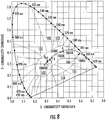
- the apparent color of visible light can be illustrated with reference to a two dimensional chromaticity diagram, such as the 1931 International Conference on Illumination (CIE) Chromaticity Diagram illustrated in Figure 8 , and the 1976 CIE u'v' Chromaticity Diagram, which is similar to the 1931 Diagram but is modified such that similar distances on the 1976 u'v' CIE Chromaticity Diagram represent similar perceived differences in color.
- CIE International Conference on Illumination
- chromaticity values are plotted using scaled u- and v- parameters which take into account differences in human visual perception. That is, the human visual system is more responsive to certain wavelengths than others. For example, the human visual system is more responsive to green light than red light.
- the 1976 CIE-u'v' Chromaticity Diagram is scaled such that the mathematical distance from one chromaticity point to another chromaticity point on the diagram is proportional to the difference in color perceived by a human observer between the two chromaticity points.
- a chromaticity diagram in which the mathematical distance from one chromaticity point to another chromaticity point on the diagram is proportional to the difference in color perceived by a human observer between the two chromaticity points may be referred to as a perceptual chromaticity space.
- a non-perceptual chromaticity diagram such as the 1931 CIE Chromaticity Diagram
- two colors that are not distinguishably different may be located farther apart on the graph than two colors that are distinguishably different.
- colors on a 1931 CIE Chromaticity Diagram are defined by x and y coordinates (i.e., chromaticity coordinates, or color points) that fall within a generally U-shaped area. Colors on or near the outside of the area are saturated colors composed of light having a single wavelength, or a very small wavelength distribution. Colors on the interior of the area are unsaturated colors that are composed of a mixture of different wavelengths.
- White light which can be a mixture of many different wavelengths, is generally found near the middle of the diagram, in the region labeled 100 in Figure 8 . There are many different hues of light that may be considered “white,” as evidenced by the size of the region 100. For example, some "white” light, such as light generated by sodium vapor lighting devices, may appear yellowish in color, while other "white” light, such as light generated by some fluorescent lighting devices, may appear more bluish in color.
- Light that generally appears green is plotted in the regions 101, 102 and 103 that are above the white region 100, while light below the white region 100 generally appears pink, purple or magenta.
- light plotted in regions 104 and 105 of Figure 8 generally appears magenta (i.e., red-purple or purplish red).
- a binary combination of light from two different light sources may appear to have a different color than either of the two constituent colors.
- the color of the combined light may depend on the relative intensities of the two light sources. For example, light emitted by a combination of a blue source and a red source may appear purple or magenta to an observer. Similarly, light emitted by a combination of a blue source and a yellow source may appear white to an observer.
- Figure 8 Also illustrated in Figure 8 is the planckian locus 106, which corresponds to the location of color points of light emitted by a black-body radiator that is heated to various temperatures.
- Figure 8 includes temperature listings along the black-body locus. These temperature listings show the color path of light emitted by a black-body radiator that is heated to such temperatures. As a heated object becomes incandescent, it first glows reddish, then yellowish, then white, and finally bluish, as the wavelength associated with the peak radiation of the black-body radiator becomes progressively shorter with increased temperature. Illuminants which produce light which is on or near the black-body locus can thus be described in terms of their correlated color temperature (CCT).
- CCT correlated color temperature
- the chromaticity of a particular light source may be referred to as the "color point” of the source.
- the chromaticity may be referred to as the "white point” of the source.
- the white point of a white light source may fall along the planckian locus. Accordingly, a white point may be identified by a correlated color temperature (CCT) of the light source.
- CCT correlated color temperature
- White light typically has a CCT of between about 2000 K and 8000 K.
- White light with a CCT of 4000 may appear yellowish in color, while light with a CCT of 8000 K may appear more bluish in color.
- Color coordinates that lie on or near the black-body locus at a color temperature between about 2500 K and 6000 K may yield pleasing white light to a human observer.
- White light also includes light that is near, but not directly on the planckian locus.
- a Macadam ellipse can be used on a 1931 CIE Chromaticity Diagram to identify color points that are so closely related that they appear the same, or substantially similar, to a human observer.
- a Macadam ellipse is a closed region around a center point in a two-dimensional chromaticity space, such as the 1931 CIE Chromaticity Diagram, that encompasses all points that are visually indistinguishable from the center point.
- a seven-step Macadam ellipse captures points that are indistinguishable to an ordinary observer within seven standard deviations
- a ten step Macadam ellipse captures points that are indistinguishable to an ordinary observer within ten standard deviations, and so on. Accordingly, light having a color point that is within about a ten step Macadam ellipse of a point on the planckian locus may be considered to have the same color as the point on the planckian locus.
- CRI color rendering index
- red light may be added to the white light, for example, by adding red emitting phosphor and/or red emitting devices to the apparatus.
- Other lighting sources may include red, green and blue light emitting devices. When red, green and blue light emitting devices are energized simultaneously, the resulting combined light may appear white, or nearly white, depending on the relative intensities of the red, green and blue sources.
- LED lighting devices may utilize one bin of LEDs, or combine matched sets of LEDs from different bins, to achieve repeatable color points for the combined output of the LEDs. Even with binning, however, LED lighting systems may still experience significant variation in color point from one system to the next.
- LED lighting systems employing feedback to obtain a desired color point are described in U.S. Publication No. 2007/0115662 (Atty Docket 5308-632) and 2007/0115228 (Atty Docket 5308-632IP) and the disclosures of which are incorporated herein by reference.
- WO-2008/142622 concerns a lighting system having a light source and a controller, configured to control at least two light attributes of the light source based on a predetermined relationship.
- US-2011/175527 concerns lighting fixtures and light bulbs containing a light transmissive optic.
- the orientation of the solid state emitters together with the contoured output surface of the light transmissive optic produce a tailored light output distribution over a designated planar surface.
- the invention provides a method of controlling a solid state lighting apparatus in accordance with claim 1 and a solid state lighting apparatus in line with claim 9.
- Some embodiments can provide methods of controlling a solid state lighting apparatus by receiving a solid state lighting characteristic selection signal at a solid state lighting apparatus and selecting, responsive to the solid state lighting characteristic selection signal, a solid state lighting model that defines a relationship between different lighting parameters used to vary light output from the solid state lighting apparatus responsive to a user input provided to the solid state lighting apparatus.
- receiving a solid state lighting characteristic selection signal at a solid state lighting apparatus can be provided by receiving the solid state lighting characteristic selection signal at the solid state lighting apparatus separate from the user input.
- the user input can be user input from a solid state lighting switch.
- the user input can be a dimming indication configured to control dimming of the light output from the solid state lighting apparatus.
- selecting a solid state lighting model can be provided by selecting among a plurality of predefined solid state lighting models each corresponding to a respective value of the solid state lighting characteristic selection signal.
- the plurality of predefined solid state lighting models are configured to vary the light output from the solid state lighting apparatus differently in response to identical user input to the solid state lighting apparatus.
- the method can further include receiving a compensation signal, at the solid state lighting apparatus, that is configured to reduce variation in the light output from the solid state lighting apparatus associated with variation in light emitted from different light emitting diodes included in the solid state lighting apparatus. In some embodiments, the method can further include receiving the compensation signal at the solid state lighting apparatus separately from the solid state lighting characteristic selection signal.
- receiving a compensation signal at the solid state lighting apparatus can be provided by receiving a combined signal including the compensation signal and the solid state lighting characteristic selection signal at solid state lighting apparatus.
- receiving a solid state lighting characteristic selection signal at a solid state lighting apparatus can be provided by receiving the solid state lighting characteristic selection signal from a circuit that is local to the apparatus and is configured during, or prior to, installation of the solid state lighting apparatus. In some embodiments, receiving a solid state lighting characteristic selection signal at a solid state lighting apparatus can be provided by receiving the solid state lighting characteristic selection signal from a circuit that is outside the apparatus and is configured to provide the solid state lighting characteristic selection signal during operation of the solid state lighting apparatus.
- the solid state lighting model can include a first solid state lighting model, where the solid state lighting characteristic selection signal can be a first value, and the relationship can be a first relationship, where the method can further include selecting, responsive to the solid state lighting characteristic selection signal having a second value, a second solid state lighting model defining a second relationship between the different lighting parameters used to vary the light output from the solid state lighting apparatus responsive to the user input provided to the solid state lighting apparatus.
- a first lighting parameter of the solid state lighting apparatus can be a dimming value and a second lighting parameter of the solid state lighting apparatus can be a color value.
- the color value can be a correlated color temperature value, a color registration index value, a color point value, or a chromaticity value.
- a third lighting parameter of the solid state lighting apparatus can be a temperature value.
- the method can further include providing circuit parameter values, based on the selected solid state lighting model, to provide the light output from the apparatus.
- the circuit parameter values can be a duty cycle signal to control a shunt level of at least one light emitting diode included in a LED string of the apparatus and a current control signal configured to control current provided to the LED string.
- the solid state lighting model is approximated by a plurality of control points of a Bézier surface that provides the duty cycle signal responsive to the current.
- receiving a solid state lighting characteristic selection signal at a solid state lighting apparatus can be provided by receiving the solid state lighting characteristic selection signal from a circuit including a resistor, a capacitor, and/or an inductor.
- a solid state lighting apparatus can include a light emitting diode (LED) string that includes a plurality of LEDs, where the LED string configured to emit light responsive to current provided to the LEDs.
- a solid state lighting characteristic selection circuit can be configured to provide a solid state lighting characteristic selection signal and a solid state lighting controller circuit, can be coupled to the LED string and to the solid state lighting characteristic selection circuit, configured to select a solid state lighting model responsive to the solid state lighting characteristic selection signal input to the controller circuit, the model configured to define a relationship between different lighting parameters used to vary the light emitted from the LED string responsive to a user input to the controller circuit.
- a solid lighting characteristic selection signal can be used to select a solid state lighting model defining a relationship between different lighting parameters used to vary light output from the solid state lighting apparatus responsive to a user input to the apparatus.
- the solid lighting characteristic selection signal (sometimes referred to herein the selection signal) has a value corresponding to a model that controls the color of light provided by the apparatus to follow the plankian locus as the intensity of the light varies (sometimes referred to incandescent style dimming).
- the term "lighting parameter" includes any indication used to specify the intensity and/or color of light emitted from the solid state lighting apparatus.
- the lighting parameter can indicate the intensity of the light to be emitted, which can be a constant or variable value.
- the lighting parameter can indicate the color of the light to be emitted, which can be a constant or variable value.
- Other lighting parameters can also be used.
- the apparatus can support any number of predefined models, one of which can, in turn, be selected by making the selection signal have a value that corresponds to the desired predefined solid state lighting model to be put into operation by the apparatus. Therefore, in some embodiments according to the invention, a large number of lighting characteristics can be supported by the apparatus so that a wide variety of user preferences can be accommodated.
- a solid state lighting characteristic selection signal circuit can be configured to provide the selection signal which corresponds to the desired predefined solid state lighting model to be provided when the apparatus is installed and operational.
- the solid state lighting characteristic selection signal may be separate from the user input to the apparatus which is used to, for example, adjust the dimming of the apparatus.
- the solid state lighting characteristic selection signal can select the predefined model which is used to provide the different circuit parameters in response to when the user adjusts the dimming of the apparatus.
- the selection signal can have a value that selects a first predefined solid state lighting model so that incandescent style is provided by the apparatus, whereas when the selection signal has a second value, a second predefined solid state lighting model is selected so that the color of the light from the apparatus remains constant over the entire range of dimming. Therefore, different predefined solid state lighting models can be selected based on the selection signal value to provide different characteristics of lighting according to user preference or specification.
- the apparatus can include a compensation circuit which provides a compensation signal configured to reduce variation in the light output from the solid state lighting apparatus which may be caused by variation in manufacturing processes over different LEDs, especially when the LEDs are included in a string of LEDs in the apparatus.
- a compensation circuit which provides a compensation signal configured to reduce variation in the light output from the solid state lighting apparatus which may be caused by variation in manufacturing processes over different LEDs, especially when the LEDs are included in a string of LEDs in the apparatus.
- LEDs that are manufactured to be identical can nonetheless emit slightly different wavelength light such that compensation may be typically provided to reduce the variation which may otherwise produce undesirable artifacts in the light provided by the apparatus.
- the compensation signal can therefore, adjust the operation of the LEDs in the apparatus so that different ones of the apparatus can provide light which is more or less the same. Compensation for variation in the manufacturing process of LEDs is described further in, for example, U.S. Patent Application Serial No. 12/704,730 (Attorney Docket No. 5308-1128IP, filed February 12, 2010),
- the compensation circuit may be separate from the solid state lighting characteristic selection circuit described herein.
- the solid state lighting characteristic selection circuit can be used to provide a signal so that the characteristics of the light output by the apparatus varies according to user preference or specification, whereas the compensation circuit may provide a signal so that the light emitted by the apparatus tends to be substantially equal across multiple ones of the apparatus.
- both the compensation signal and the selection signal are provided to the apparatus, so that if the same predefined solid state lighting model is selected in two different apparatus, the compensation signal will help reduce variation between the two different apparatus.
- the compensation circuit and the solid state lighting characteristics selection circuit can be combined so that a combined signal is provided to the apparatus.
- the combined signal can include a solid state lighting characteristic selection signal component and a compensation component.
- the selection signal and the compensation signal may be provided separately to the apparatus.
- the solid state lighting characteristic selection signal can be provided by a circuit that is local to the apparatus and is configured during, or prior to, installation of the apparatus, such as during the manufacturing process. Therefore, once installed, the apparatus can provide light according to the characteristics selected by the selection signal for the entire time that the apparatus operates.
- the solid state lighting characteristics selection signal can be provided by a circuit which is remote from (i.e. outside) the apparatus. In such embodiments, the solid state lighting characteristic selection signal may be varied after installation if, for example, the predefined solid state lighting model selected during manufacturing is determined to be inadequate after installation or it is desired that the solid state lighting model should be selected after installation of the apparatus.
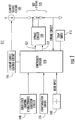
- FIG. 1 is a block diagram that illustrates a solid state lighting apparatus 111 in some embodiments according to the invention.
- a controller circuit 110 operates responsive to a solid state lighting characteristic selection signal to select among a plurality of predefined solid state lighting models, each of which can define a relationship between different lighting parameters used to vary the light output from the apparatus in response to a user input provided by a remote solid state lighting switch 130.
- the switch 130 can be any type of switch that is adequate to vary the dimming value to the apparatus 111.
- the switch 130 can have a "slider" input that moves in a straight line between the lowest most and the uppermost positions.
- the input can be a knob that rotate between positions.
- the dimming indication can be a voltage signal that varies between 0 and 10 volts. Other voltage ranges can also be used.
- the input can be electronic, rather than mechanical.
- the input can be compatible with the Digital Addressable Lighting Interface (DALI) protocol, originally part of Europe's Standard 60929, which is a NEMA Standard (243-2004) in the United States.
- DALI Digital Addressable Lighting Interface
- the controller circuit 110 can receive the selection signal from a solid state lighting characteristic selection circuit 140 to select one of the plurality of predefined solid state lighting models to provide a selected relationship that will be maintained between different lighting parameters as the user input changes.
- the selected predefined solid state lighting model may define the relationship between a dimming value and a color value so that the light output from the apparatus 111 follows the plankian 100 as the input from the switch 130 varies.
- a different value of the selection signal can select a different predefined solid state lighting model so that, for example, the dimming value and the color value are maintained in a different relationship (e.g., constant color dimming) as the user input varies.
- the color value may be held constant so that despite the intensity of the light provided by the apparatus 111, the color remains constant. It will understood that other solid state lighting models may be utilized to provide other characteristic type lighting. Lighting parameters other than dimming and color may also be used.
- the predefined solid state lighting models may be represented as the surfaces shown in Figures 6 and 7 .
- the models represented by the surfaces in Figures 6 and 7 can relate the different lighting parameters (such as a dimming value and a color value) so that corresponding circuit parameter values are provided by the controller circuit 110 to affect the light emitted by the apparatus 111. Therefore, in operation, the controller circuit 110 can select a model represented by the surfaces shown for example in Figures 6 and 7 to relate the different lighting parameters in order to generate values for circuit parameters used to control the apparatus 111 so that the light emitted by the apparatus 111 reflects the lighting parameters.
- the solid state lighting characteristic selection signal can be assigned any value (within any range) which is predefined to correspond to a particular predefined solid state lighting model that is accessible to the controller circuit 110.
- the selection signal can have any one of N values where each of the discrete values of the selection signal within the N values corresponds to one of the predefined solid state lighting models that may be put into operation by the controller circuit 110.
- the first value of the selection signal can be predefined to correspond to a lighting style that is characterized by an incandescent style of dimming.
- Another value of the selection signal can be predefined to correspond to another of the predefined solid state lighting models which allows the controller circuit 110 to put into effect the constant color dimming.
- the controller circuit 110 can provide circuit parameter values to control an LED string 145 (including a plurality of LEDs) to emit light that is characterized by the different lighting parameters described herein.
- the controller circuit 110 uses the selected predefined model to control a current source control circuit 125 to generate a current circuit parameter value (i.e., a current) from a current source circuit 150.
- the current generated by the current source circuit 150 causes light at a particular intensity to be emitted by the LED string 145 in accordance with the dimming parameter.
- the controller circuit 110 also provides duty cycle signals CL1 and CL2, as circuit parameter values, to a bypass circuit 120.
- the bypass circuit 120 is coupled in parallel with selected ones of the LEDs included in the string 145.
- the bypass circuit 120 operates in response to the duty cycle signals CL1 and CL2 to selectively bypass the selected ones of the LEDs to cause the LEDs in the string 145 to generate light having a color that is in accordance with the color value lighting parameter.
- the controller circuit 110 can also receive a temperature as a circuit parameter value that indicates the temperature in which the apparatus 111 operates.
- the temperature value can be used by the controller circuit 110 to modify the other circuit parameter values so that the light emitted by the string 145 is maintained in accordance with the lighting parameters.
- a compensation signal is provided to the controller circuit 110 by a compensation circuit 135.
- the compensation signal can be used to compensate for variations in the light emitted by different ones of the LEDs in the string 145.
- the variations in the light output by the different LEDs may result from differences in the process used to manufacture the LEDs.
- some LEDs which are manufactured to be identical may actually emit slightly different frequencies of light due to, for example, differences in the phosphor included in the LED. Accordingly, the compensation signal can be used to take into account the variation between the LEDs when controlling LEDs that do not produce identical light despite identical inputs.
- the compensation associated with the variation in the LEDs described above can be taken into account when generating the predefined solid state lighting models that relate the different lighting parameters to one another.
- the compensation signal can characterize the differences between the LEDs so that a proper set of predefined solid state lighting models are identified for operation by the controller circuit 110.
- the solid state lighting characteristic selection signal can be used to select among those predefined solid state lighting models that are identified by the compensation signal.
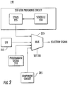
- FIG. 2 is a block diagram that illustrates the solid state lighting characteristic selection circuit 140 in some embodiments according to the invention.
- the solid state lighting characteristic selection signal can be provided by a multiplexor circuit 235 to select among a plurality of inputs using a setting that can identify the mode by which the selection signal is to be provided.
- Each of the inputs to the multiplexor circuit 235 can be provided with a particular type of selection signal, any one of which may be ultimately provided to the controller circuit 110.
- one of the inputs of the multiplexor circuit 235 is coupled to a user preference circuit 220 that can store particular styles of solid state lighting characteristics 225, any one of which may be selected by a schedule 230.
- the schedule 230 may specify different lighting characteristics that may be used at different times of the day, days of the week etc., which may in turn be provided as the selection signal by the multiplexor circuit 235. Therefore, the user may specify various types of lighting characteristics that can be expressed as corresponding selection signal values which can be provided to the apparatus 111 using the preference circuit 220 to select a predefined model, rather than providing a static selection signal to the controller circuit 110.
- a wireless interface circuit 215 can be coupled to another of the inputs to the multiplexor circuit 235 to provide a different version of the selection signal to the controller circuit 110.
- a wireless remote control may be utilized to specify a selection signal to the interface circuit 215, which may then be provided as the selection signal to the controller circuit 110.
- the wireless interface circuit 215 interfaces to a remote control which may be utilized by a user who can specify a particular solid state lighting model to be utilized by the controller circuit 110. Again, the approach taken here may be to provide a variation in the different lighting characteristics provided by the apparatus 111 in accordance with the user's preference after installation of the apparatus 111.
- a programmed signal circuit 210 may store different versions of the selection signal which may be accessed and provided to the controller circuit 110 by the multiplexor circuit 235. Accordingly, the selection signal values can be stored within the program signal circuit 210 in advance and configured to provide one of the selection signal values upon installation.
- a component circuit 205 can also be coupled to another of the inputs to the multiplexor circuit 235 to provide a type of static selection signal to the controller circuit 110.
- the component circuits 205 may be passive components that are arranged in, for example, networks to provide various values for the selection signal so that the controller circuit 110 may be controlled to select any of the predefined solid state lighting models accessible thereto. Also, any of the selection circuits shown in Figure 2 may be used separately and without the multiplexor circuit 235.
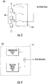
- FIG 3 is a block diagram that illustrates the component circuits 205 illustrated in Figure 2 in some embodiments according to the invention.
- the selection signal can be provided by a network 305 of passive components coupled in series with one another to a voltage V.
- the voltage across each of the passive components in the network 305 can provide a different value that the selection signal can be assigned.
- the appropriate value of the selection signal can be selected by a series of switches 310 coupled across the network 305 whereupon one of the switches corresponding to the selected value of the selection signal is closed so that the voltage is provided to the controller circuit 110, whereas the remaining switches are left open.
- the network 305 can include any type of passive component such as resistors, capacitors, inductors or combinations thereof.
- Figure 4 is a block diagram illustrating a solid state lighting characteristic selection circuit 405 including aspects of the compensation circuit 135 combined with those of the solid state lighting characteristic selection circuit 140.
- the combined signal can include components of the selection signal as well as the compensation signal combined with one another provided to a single input of the controller circuit 110, which may separate the components from the combined signal so that both the compensation signal and the selection signal may be provided for operation of the controller circuit 110.
- the combination of the components can be provided by time or frequency multiplexing the components together.
- the combination of the components can be added together to provide a composite signal that includes both components.
- FIG. 5 is a block diagram that illustrates the lighting apparatus 111 of Figure 1 in further detail in some embodiments according to the invention.
- the selection signal, compensation signal, and user input can be provided to the controller circuit 110 as described above.
- the current source control circuit 125 can operate responsive to the controller circuit 110 to control the current provided by the current source circuit 150 as described above in reference to Figure 1 .
- the controller circuit 110 can provide the duty cycle signals CL1 and CL2 to the bypass circuit 120 as described in reference to Figure 1 .
- FIG. 5 further illustrates a more detailed view of the LED string 145 and exemplary components within the bypass circuit 120 in some embodiments according to the invention.
- Embodiments according to the present invention can utilize bypass compensation circuits (i.e ., bypass circuits) as described in co-pending and commonly assigned U.S. Patent Application Serial No. 12/566,195 entitled “Solid State Lighting Apparatus with Controllable Bypass Circuits and Methods of Operating Thereof” and co-pending and commonly assigned U.S. Patent Application Serial No. 12/566,142 entitled “Solid State Lighting Apparatus with Configurable Shunts", the disclosures of which are incorporated herein by reference.
- the two circuits included in the bypass circuit 120 can be referred to separately as bypass circuits or collectively as a bypass circuit, when for example, two bypass circuits are used to control the color of the light emitted by the LED string 145.
- the bypass circuits 120 may switch between LED(s), variably shunt around LED(s) and/or bypass LED(s) in the string 145 using the duty cycle signals provided by the controller circuit 110 in response to the user input and the selected predefined solid state lighting model.
- the output of the string 145 is modeled based on one or more variables, such as current, temperature and/or LED bins (brightness and/or color bins) used, and the level of bypass/shunting employed. The model may be adjusted for variations in individual lighting devices.
- the LED string 145 includes a plurality of LEDs (LED 1 through LED9) connected in series between a voltage source V and ground.
- the controller circuit 110 is coupled to the string 145 and control gates of transistors Q1 and Q2 via duty cycles signals CL1 and CL2.
- the string 145 may include LEDs that emit different colors of light when current is passed through the string 145.
- some of the LEDs may include phosphor coated LEDs that emit broad spectrum white, or near-white light when energized.
- Some of the LEDs may be configured to emit blue shifted yellow (BSY) light as disclosed, for example, in commonly assigned U.S. Patent No. 7,213,940 issued May 8. 2007 , entitled “Lighting Device And Lighting Method", and/or blue-shifted red (BSR) light as disclosed in U.S. Application Serial No. 12/425,855, filed April 19, 2009 , entitled "Methods for Combining Light Emitting Devices in a Package and Packages Including Combined Light Emitting Devices", or United States Patent No.
- BSR blue-shifted red
- LEDs may emit saturated or near-saturated narrow spectrum light, such as blue, green, amber, yellow or red light when energized.
- the LEDs may be BSY, red and blue LEDs as described in co-pending and commonly assigned United States Patent Application Publication No. 2009/0184616 , the disclosure of which is incorporated herein by reference, phosphor converted white or other combinations of LEDs, such as red-green-blue (RGB) and/or red-green-blue-white (RGBW) combinations.
- LED5 and LED6 may be red LEDs and LED7 may be a blue LED. The remaining LEDs may be BSY and/or red LEDs.
- the LED string 145 includes subsets of LEDs that may be selectively bypassed by activation of transistors Q1 and Q2. For example, when transistor Q1 is switched on, LED5 and LED6 are bypassed, and non-light emitting diodes D1, D2 and D3 are switched into the string 145. Similarly, when transistor Q2 is switched on, LED7 is bypassed, and non-light emitting diodes D4 and D5 are switched into the string 145. Non-light emitting Diodes D1 through D5 are included so that variations in the overall string voltage are reduced when LED5, LED6 and LED7 are switched out of the string by transistors Q1 and Q2,
- the controller circuit 110 controls the duty cycles of the transistors Q1 and Q2 using duty cycle signals CL1 and CL2 based on the predefined solid state lighting model selected by the selection signal.
- the duty cycles of the transistors Q1 and Q2 may be controlled as described, for example, in U.S. Application Serial No. 12/968,789 , entitled "LIGHTING APPARATUS USING A NON-LINEAR CURRENT SENSOR AND METHODS OF OPERATION THEREOF" filed December 15, 2010, the disclosure of which is incorporated herein.
- the duty cycles of the transistors Q1 and Q2 may be controlled so that the total combined light output by the LED string 145 has the desired color.
- Predictive models can be developed to provide the solid state lighting models described herein to allow tuning and operational control of the LEDs in the apparatus 111.
- a Bezier surface can be constructed based on the variables of lighting parameters (such as a color and intensity), temperature, current level (dimming indication) and shunt level associated with the duty cycle. These Bezier surfaces may then be used as a model to control the operation of the apparatus 111 having the same combination of LEDs as the reference set of LEDs.
- a Bezier surface is a mathematical tool that can model a multidimensional function using a finite number of control points.
- a number of control points are selected that define a surface in an M-dimensional space.
- the surface is defined by the control points in a manner similar to interpolation.
- the surface is defined by the control points, the surface does not necessarily pass through the control points. Rather, the surface is deformed towards the control points, with the amount of deformation being constrained by the other control points.
- the Bezier surface can be defined to model a given M-dimensional space, where each of the M-dimensions corresponds to a particular parameter used to control operation of the lighting apparatus.
- the M-dimensions can include parameters such as shunt level, ambient temperature, current, and the selection signal.
- the number dimensions used can be arbitrary.
- a Bezier surface can be define to model a space that has more (or less) dimensions. For example, if a new parameter, such as compensation, is to be considered in controlling the lighting apparatus, the compensation parameter can be added to define a new Bezier surface based on these five parameters as described herein.
- a given Bezier surface of order (n, m) is defined by a set of (n + 1)(m + 1) control points k i,j .
- Bezier surfaces used to represent solid state lighting models to define relationships between lighting parameters are illustrated in Figures 6 and 7 .
- the Bezier surface 300 illustrated in Figure 6 represents an LED shunt level (z-axis) associated with the duty cycle, plotted as a function of temperature (x-axis) and current (y-axis) of a solid state lighting apparatus 111, defined by sixteen control points 310, which are points in the three-dimensional space represented by the x-, y- and z- axes shown in Figure 6 .
- the surface 300 represents a first solid state lighting model (selected by a first value for the selection signal) that defines a first relationship between the lighting parameters (e.g., intensity and color) used to vary light output from the solid state lighting apparatus responsive to a user input provided to the solid state lighting apparatus.
- the Bezier surface 300 provides a mathematically convenient model for a multidimensional relationship, such as modeling LED shunt level as a function of temperature and current for a given output color, because the Bezier surface is completely characterized by a finite number of control points (e.g. sixteen).
- a five-axis model (u',v',T, I and S) can be collapsed based on the desired color point (u',v'), or color, to a three-axis model in which the shunt level (i.e ., duty cycle) is determined as a function of current (I) used as the dimming indication, and temperature. That is, a three-axis model is constructed in which shunt level is dependent on current and selection signal value for a given color point selected by the user.
- the shunt level i.e ., duty cycle
- a set of control points which in some embodiments may include 16 control points, is established for the desired u',v' color indication, such that the shunt level or duty cycle of the a selected group of one or more controlled red LEDs required to achieve the desired (u' ,v') color indication, is a dependent variable based on temperature and current level.
- a corresponding family of sets of 16 control points is established for the desired u',v' color indication such that the shunt level of a group of one or more controlled blue LEDs required to achieve the desired (u',v') color indication is a dependent variable based on temperature and current level.
- a surface 305 represents a second solid state lighting model (selected by a second value for the selection signal) that defines a second relationship between the lighting parameters used to vary light output from the solid state lighting apparatus responsive to a user input provided to the solid state lighting apparatus. Accordingly, when the selection signal has the first value, the surface 300 can be used by the controller circuit 110 to operate the apparatus 111, whereas when the selection signal has the second value, the surface 305 can be used by the controller circuit 110 to operate the apparatus 111.
- Each of the Bezier surfaces 300, 305 therefore, represent a respective predefined solid state lighting model that defines the relationship between the different lighting parameters used to vary light output from the LED string 145 responsive to user input to the controller circuit 110.
- One or the other of the models can be selected based on the value of the selection signal. It will be understood that more than two models may be used.
- the selection signal can be considered to be an additional dimension (as part of the M-dimensional space) to be modeled by the Bezier surface.
- the Bezier surfaces 300, 305 are shown as discrete from one another and separated by a particular value for the selection signal, the Bezier surfaces 300, 305 may be relatively close to one another within the space show. Moreover, in some embodiments according to the invention, the Bezier surfaces 300, 305 can be close enough to one another that they represent a substantially continuous range of Bezier surfaces that can be accessed. In other words, the Bezier surfaces 300, 305 can be close enough to one another so that the user may perceive the change in operation in switching from one the Bezier surfaces to another as essentially continuous so that no appreciable discontinuity is observed in the operation of the lighting apparatus.
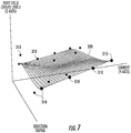
- Figure 7 illustrates a single Bezier surface representing a solid state lighting model defining a relationship between different lighting parameters used to vary light output from the apparatus 111 responsive to user input according to some embodiments according to the invention.
- the particular value of the selection signal can select a two-dimensional slice of the surface 306 in the x-axis and y-axis directions.
- the selected slice of the surface 306 represents a curve relating to current and duty cycle (i.e., shunt level) that can be used as circuit parameter values to operate the apparatus 111.
- each of the different values of the selection signal along the x-axis can represent a different one of the predefined solid state lighting models supported by the controller circuit 110.
- the value of the selection signal specifies the particular portion of the surface used to generate the circuit parameter values, such as the current generated by the current source circuit 105 and the duty cycle signals CL1 and CL2 provided to the bypass circuit 120 so that the light emitted by the LED string 145 is in accordance with the lighting parameters (such as dimming and color values) in response to the user input received by the controller circuit 110.
- the use of Bezier surfaces in controlling operations of lighting fixtures is described further in commonly assigned U.S.
- a solid lighting characteristic selection signal can be used to select a solid state lighting model defining a relationship between different lighting parameters used to vary light output from the solid state lighting apparatus responsive to a user input to the apparatus.
- the solid lighting characteristic selection signal (sometimes referred to herein a the selection signal) has a value corresponding to a model that controls the color of light provided by the apparatus to follow the plankian locus as the intensity of the light varies (sometimes referred to incandescent style dimming).
Landscapes
- Circuit Arrangement For Electric Light Sources In General (AREA)
Claims (13)
- Procédé de commande d'un appareil d'éclairage à semi-conducteurs (111), le procédé comprenant le fait :de recevoir un signal de sélection de caractéristique d'éclairage à semi-conducteurs au niveau d'un appareil d'éclairage à semi-conducteurs ;de sélectionner, en réponse au signal de sélection de caractéristique d'éclairage à semi-conducteurs, un modèle d'éclairage à semi-conducteurs définissant une relation entre des paramètres d'éclairage différents utilisés pour faire varier la sortie de lumière provenant de l'appareil d'éclairage à semi-conducteurs en réponse à une entrée utilisateur fournie à l'appareil d'éclairage à semi-conducteurs ;de recevoir un signal de compensation, au niveau de l'appareil d'éclairage à semi-conducteurs, configuré pour réduire la variation de la sortie de lumière provenant de l'appareil d'éclairage à semi-conducteurs en raison de la variation des processus de fabrication des diodes électroluminescentes incluses dans l'appareil d'éclairage à semi-conducteurs ; etdans lequel la réception d'un signal de sélection de caractéristique d'éclairage à semi-conducteurs au niveau d'un appareil d'éclairage à semi-conducteurs comprend la réception du signal de sélection de caractéristique d'éclairage à semi-conducteurs à partir d'un circuit (140) qui se trouve dans l'appareil et qui est configuré pendant, ou avant, l'installation de l'appareil d'éclairage à semi-conducteurs.
- Procédé de la revendication 1, dans lequel la réception d'un signal de sélection de caractéristique d'éclairage à semi-conducteurs au niveau d'un appareil d'éclairage à semi-conducteurs comprend la réception du signal de sélection de caractéristique d'éclairage à semi-conducteurs au niveau de l'appareil d'éclairage à semi-conducteurs séparé de l'entrée utilisateur.
- Procédé de la revendication 2, dans lequel l'entrée utilisateur comprend une entrée utilisateur provenant d'un interrupteur d'éclairage à semi-conducteurs.
- Procédé de la revendication 3, dans lequel l'entrée utilisateur comprend une indication de gradation configurée pour commander la gradation de la sortie de lumière provenant de l'appareil d'éclairage à semi-conducteurs.
- Procédé de la revendication 1, dans lequel la sélection d'un modèle d'éclairage à semi-conducteurs comprend la sélection parmi une pluralité de modèles d'éclairage à semi-conducteurs prédéfinis correspondant chacun à une valeur respective du signal de sélection de caractéristique d'éclairage à semi-conducteurs.
- Procédé de la revendication 5, dans lequel la pluralité de modèles d'éclairage à semi-conducteurs prédéfinis sont configurés pour faire varier la sortie de lumière provenant de l'appareil d'éclairage à semi-conducteurs différemment en réponse à une entrée utilisateur identique dans l'appareil d'éclairage à semi-conducteurs.
- Procédé de la revendication 1, comprenant en outre le fait :de recevoir le signal de compensation au niveau de l'appareil d'éclairage à semi-conducteurs séparément du signal de sélection de caractéristique d'éclairage à semi-conducteurs.
- Procédé de la revendication 1, dans lequel la réception d'un signal de compensation au niveau de l'appareil d'éclairage à semi-conducteurs comprend la réception d'un signal combiné comportant le signal de compensation et le signal de sélection de caractéristique d'éclairage à semi-conducteurs au niveau de l'appareil d'éclairage à semi-conducteurs.
- Appareil d'éclairage à semi-conducteurs (111) comprenant :une chaîne de diodes électroluminescentes, LED, (145) comportant une pluralité de LED, la chaîne de LED étant configurée pour émettre de la lumière en réponse à un courant fourni aux LED ;un circuit de sélection de caractéristique d'éclairage à semi-conducteurs (140) configuré pour fournir un signal de sélection de caractéristique d'éclairage à semi-conducteurs ;un circuit de commande d'éclairage à semi-conducteurs (110), couplé à la chaîne de LED (145) et au circuit de sélection de caractéristique d'éclairage à semi-conducteurs (140), configuré pour sélectionner un modèle d'éclairage à semi-conducteurs en réponse au signal de sélection de caractéristique d'éclairage à semi-conducteurs introduit dans le circuit de commande, le modèle étant configuré pour définir une relation entre des paramètres d'éclairage différents utilisés pour faire varier la lumière émise à partir de la chaîne de LED en réponse à une entrée utilisateur dans le circuit de commande ; etun circuit de compensation (135), couplé au circuit de commande d'éclairage à semi-conducteurs (110), le circuit de compensation étant configuré pour fournir un signal de compensation au circuit de commande d'éclairage à semi-conducteurs configuré pour réduire la variation de la lumière émise à partir de la chaîne de LED en raison de la variation des processus de fabrication des LED incluses dans l'appareil d'éclairage à semi-conducteurs.
- Appareil de la revendication 9, dans lequel le circuit de commande d'éclairage à semi-conducteurs comprend en outre :une entrée de sélection de caractéristique d'éclairage à semi-conducteurs, couplée au signal de sélection de caractéristique d'éclairage à semi-conducteurs, où l'entrée de sélection de caractéristique d'éclairage à semi-conducteurs est séparée de l'entrée utilisateur dans le circuit de commande d'éclairage à semi-conducteurs.
- Appareil de la revendication 10, dans lequel l'entrée utilisateur est configurée pour être couplée à un interrupteur d'éclairage à semi-conducteurs distant de l'appareil.
- Appareil de la revendication 10, dans lequel l'entrée utilisateur comprend une entrée d'indication de gradation configurée pour commander la gradation de la sortie de lumière provenant de l'appareil d'éclairage à semi-conducteurs.
- Appareil de la revendication 9, dans lequel le circuit de sélection de caractéristique d'éclairage à semi-conducteurs comprend au moins un composant passif configuré pour fournir le signal de sélection de caractéristique d'éclairage à semi-conducteurs.
Applications Claiming Priority (3)
| Application Number | Priority Date | Filing Date | Title |
|---|---|---|---|
| US201161579986P | 2011-12-23 | 2011-12-23 | |
| US13/416,613 US10187942B2 (en) | 2011-12-23 | 2012-03-09 | Methods and circuits for controlling lighting characteristics of solid state lighting devices and lighting apparatus incorporating such methods and/or circuits |
| PCT/US2012/070897 WO2013096599A1 (fr) | 2011-12-23 | 2012-12-20 | Procédés et circuits de commande de caractéristiques d'éclairage de dispositifs d'éclairage à semi-conducteurs, et appareil d'éclairage comprenant ces procédés et/ou circuits |
Publications (3)
| Publication Number | Publication Date |
|---|---|
| EP2805578A1 EP2805578A1 (fr) | 2014-11-26 |
| EP2805578A4 EP2805578A4 (fr) | 2016-06-01 |
| EP2805578B1 true EP2805578B1 (fr) | 2017-12-13 |
Family
ID=48653842
Family Applications (1)
| Application Number | Title | Priority Date | Filing Date |
|---|---|---|---|
| EP12860560.7A Active EP2805578B1 (fr) | 2011-12-23 | 2012-12-20 | Procédés et circuits de commande de caractéristiques d'éclairage de dispositifs d'éclairage à semi-conducteurs, et appareil d'éclairage comprenant ces procédés et/ou circuits |
Country Status (3)
| Country | Link |
|---|---|
| US (1) | US10187942B2 (fr) |
| EP (1) | EP2805578B1 (fr) |
| WO (1) | WO2013096599A1 (fr) |
Families Citing this family (8)
| Publication number | Priority date | Publication date | Assignee | Title |
|---|---|---|---|---|
| US8947003B2 (en) * | 2013-03-28 | 2015-02-03 | Flextronics Automotive Inc. | Circuit and method for independent control of series connected light emitting diodes |
| DE102013224760B4 (de) * | 2013-12-03 | 2022-09-29 | Tridonic Gmbh & Co Kg | Treiberschaltung und Verfahren zum Betrieb einer dimmbaren LED-Strecke in einem Dimmbereich mit zwei Bereichen |
| US10531545B2 (en) | 2014-08-11 | 2020-01-07 | RAB Lighting Inc. | Commissioning a configurable user control device for a lighting control system |
| US10477636B1 (en) | 2014-10-28 | 2019-11-12 | Ecosense Lighting Inc. | Lighting systems having multiple light sources |
| TWI583249B (zh) * | 2016-02-03 | 2017-05-11 | 凱鈺科技股份有限公司 | 可調色溫的發光模組與調光系統以及可調整發光模組之發光色溫的控制模組 |
| US10483850B1 (en) | 2017-09-18 | 2019-11-19 | Ecosense Lighting Inc. | Universal input-voltage-compatible switched-mode power supply |
| US12156307B2 (en) * | 2020-06-09 | 2024-11-26 | Signify Holding B.V. | Method of controlling a lighting emitting diode lighting device and a light emitting diode, LED, based lighting device |
| US20220117062A1 (en) * | 2020-10-13 | 2022-04-14 | G&G Led, Llc | Method and System for Changing a Function of a Lighting Device |
Family Cites Families (24)
| Publication number | Priority date | Publication date | Assignee | Title |
|---|---|---|---|---|
| US7405715B2 (en) | 2001-08-09 | 2008-07-29 | Guzman Robert G | LED light apparatus with instantly adjustable color intensity |
| CN1784932B (zh) | 2003-05-07 | 2011-09-28 | 皇家飞利浦电子股份有限公司 | 用来控制发光二极管的用户界面 |
| US20060237636A1 (en) * | 2003-06-23 | 2006-10-26 | Advanced Optical Technologies, Llc | Integrating chamber LED lighting with pulse amplitude modulation to set color and/or intensity of output |
| AU2006255105C1 (en) | 2005-06-06 | 2010-10-21 | Lutron Electronics Co., Inc. | Dimmer switch for use with lighting circuits having three-way switches |
| US7926300B2 (en) | 2005-11-18 | 2011-04-19 | Cree, Inc. | Adaptive adjustment of light output of solid state lighting panels |
| JP5249773B2 (ja) | 2005-11-18 | 2013-07-31 | クリー インコーポレイテッド | 可変電圧ブースト電流源を有する固体照明パネル |
| US7213940B1 (en) | 2005-12-21 | 2007-05-08 | Led Lighting Fixtures, Inc. | Lighting device and lighting method |
| JP2009526385A (ja) | 2006-02-10 | 2009-07-16 | ティーアイアール テクノロジー エルピー | 光源輝度制御システム及び方法 |
| US7821194B2 (en) | 2006-04-18 | 2010-10-26 | Cree, Inc. | Solid state lighting devices including light mixtures |
| JP5188690B2 (ja) * | 2006-08-29 | 2013-04-24 | アバゴ・テクノロジーズ・イーシービーユー・アイピー(シンガポール)プライベート・リミテッド | Ledを駆動するための装置及び方法 |
| US7560677B2 (en) * | 2007-03-13 | 2009-07-14 | Renaissance Lighting, Inc. | Step-wise intensity control of a solid state lighting system |
| WO2008142622A1 (fr) | 2007-05-22 | 2008-11-27 | Koninklijke Philips Electronics N.V. | Contrôleur de gradation personnalisée |
| US7675248B2 (en) * | 2007-06-01 | 2010-03-09 | Honeywell International Inc. | Dual mode searchlight dimming controller systems and methods |
| CN101821544B (zh) | 2007-10-10 | 2012-11-28 | 科锐公司 | 照明装置及制造方法 |
| US8866410B2 (en) | 2007-11-28 | 2014-10-21 | Cree, Inc. | Solid state lighting devices and methods of manufacturing the same |
| US8356916B2 (en) | 2008-05-16 | 2013-01-22 | Musco Corporation | Method, system and apparatus for highly controlled light distribution from light fixture using multiple light sources (LEDS) |
| US7967652B2 (en) | 2009-02-19 | 2011-06-28 | Cree, Inc. | Methods for combining light emitting devices in a package and packages including combined light emitting devices |
| US10264637B2 (en) | 2009-09-24 | 2019-04-16 | Cree, Inc. | Solid state lighting apparatus with compensation bypass circuits and methods of operation thereof |
| US9713211B2 (en) | 2009-09-24 | 2017-07-18 | Cree, Inc. | Solid state lighting apparatus with controllable bypass circuits and methods of operation thereof |
| US8901829B2 (en) | 2009-09-24 | 2014-12-02 | Cree Led Lighting Solutions, Inc. | Solid state lighting apparatus with configurable shunts |
| DE102010000672A1 (de) | 2010-01-05 | 2011-07-07 | Tridonic Ag | Kombiniertes Verfahren zum Betreiben eines elektrischen Leuchtmittels sowie Betriebsschaltung |
| US8128262B2 (en) | 2010-03-30 | 2012-03-06 | Abl Ip Holdings Llc | Lighting applications with light transmissive optic contoured to produce tailored light output distribution |
| US8569974B2 (en) | 2010-11-01 | 2013-10-29 | Cree, Inc. | Systems and methods for controlling solid state lighting devices and lighting apparatus incorporating such systems and/or methods |
| US10057952B2 (en) | 2010-12-15 | 2018-08-21 | Cree, Inc. | Lighting apparatus using a non-linear current sensor and methods of operation thereof |
-
2012
- 2012-03-09 US US13/416,613 patent/US10187942B2/en active Active
- 2012-12-20 EP EP12860560.7A patent/EP2805578B1/fr active Active
- 2012-12-20 WO PCT/US2012/070897 patent/WO2013096599A1/fr not_active Ceased
Non-Patent Citations (1)
| Title |
|---|
| None * |
Also Published As
| Publication number | Publication date |
|---|---|
| US20130162151A1 (en) | 2013-06-27 |
| EP2805578A1 (fr) | 2014-11-26 |
| US10187942B2 (en) | 2019-01-22 |
| EP2805578A4 (fr) | 2016-06-01 |
| WO2013096599A1 (fr) | 2013-06-27 |
Similar Documents
| Publication | Publication Date | Title |
|---|---|---|
| US9854634B2 (en) | Solid state lighting switches and fixtures providing dimming and color control | |
| EP2636035B1 (fr) | Systèmes et procédés de commande de dispositifs d'éclairage à semi-conducteurs et appareil d'éclairage incorporant ces systèmes et/ou procédés | |
| US10187942B2 (en) | Methods and circuits for controlling lighting characteristics of solid state lighting devices and lighting apparatus incorporating such methods and/or circuits | |
| US8847516B2 (en) | Lighting devices including current shunting responsive to LED nodes and related methods | |
| US9706611B2 (en) | Solid state lighting apparatuses, circuits, methods, and computer program products providing targeted spectral power distribution output using pulse width modulation control | |
| US10231300B2 (en) | Systems and methods for controlling solid state lighting during dimming and lighting apparatus incorporating such systems and/or methods | |
| US10264638B2 (en) | Circuits and methods for controlling solid state lighting | |
| US8884554B2 (en) | Colorizer and method of operating the same | |
| EP2791973B1 (fr) | Dispositifs d'éclairage comprenant une dérivation de courant répondant aux n uds de del et procédés associés | |
| TW202107940A (zh) | 色彩調諧應用之選擇參數 | |
| TW202111685A (zh) | 用於視覺均勻色彩調諧之控制設計 | |
| US20190313502A1 (en) | Calibration Of Drivers Of A Light Source | |
| US20140210355A1 (en) | Methods, circuits and systems for adjusting chromaticity of solid state lighting | |
| JP2022530708A (ja) | 暖色化減光led回路 | |
| TW201230873A (en) | Systems and methods for controlling solid state lighting devices and lighting apparatus incorporating such systems and/or methods | |
| WO2014165450A1 (fr) | Circuits et procédés de contrôle d'éclairage à l'état solide |
Legal Events
| Date | Code | Title | Description |
|---|---|---|---|
| PUAI | Public reference made under article 153(3) epc to a published international application that has entered the european phase |
Free format text: ORIGINAL CODE: 0009012 |
|
| 17P | Request for examination filed |
Effective date: 20140723 |
|
| AK | Designated contracting states |
Kind code of ref document: A1 Designated state(s): AL AT BE BG CH CY CZ DE DK EE ES FI FR GB GR HR HU IE IS IT LI LT LU LV MC MK MT NL NO PL PT RO RS SE SI SK SM TR |
|
| DAX | Request for extension of the european patent (deleted) | ||
| RA4 | Supplementary search report drawn up and despatched (corrected) |
Effective date: 20160429 |
|
| RIC1 | Information provided on ipc code assigned before grant |
Ipc: H05B 33/08 20060101ALI20160422BHEP Ipc: H05B 37/02 20060101AFI20160422BHEP |
|
| GRAP | Despatch of communication of intention to grant a patent |
Free format text: ORIGINAL CODE: EPIDOSNIGR1 |
|
| INTG | Intention to grant announced |
Effective date: 20170704 |
|
| RIN1 | Information on inventor provided before grant (corrected) |
Inventor name: CHOBOT, JOSEPH PAUL Inventor name: VAN DE VEN, ANTONY, P. |
|
| GRAS | Grant fee paid |
Free format text: ORIGINAL CODE: EPIDOSNIGR3 |
|
| GRAA | (expected) grant |
Free format text: ORIGINAL CODE: 0009210 |
|
| AK | Designated contracting states |
Kind code of ref document: B1 Designated state(s): AL AT BE BG CH CY CZ DE DK EE ES FI FR GB GR HR HU IE IS IT LI LT LU LV MC MK MT NL NO PL PT RO RS SE SI SK SM TR |
|
| REG | Reference to a national code |
Ref country code: GB Ref legal event code: FG4D |
|
| REG | Reference to a national code |
Ref country code: AT Ref legal event code: REF Ref document number: 955480 Country of ref document: AT Kind code of ref document: T Effective date: 20171215 Ref country code: CH Ref legal event code: EP |
|
| REG | Reference to a national code |
Ref country code: IE Ref legal event code: FG4D |
|
| REG | Reference to a national code |
Ref country code: DE Ref legal event code: R096 Ref document number: 602012040985 Country of ref document: DE |
|
| REG | Reference to a national code |
Ref country code: NL Ref legal event code: MP Effective date: 20171213 |
|
| REG | Reference to a national code |
Ref country code: LT Ref legal event code: MG4D |
|
| PG25 | Lapsed in a contracting state [announced via postgrant information from national office to epo] |
Ref country code: NO Free format text: LAPSE BECAUSE OF FAILURE TO SUBMIT A TRANSLATION OF THE DESCRIPTION OR TO PAY THE FEE WITHIN THE PRESCRIBED TIME-LIMIT Effective date: 20180313 Ref country code: SE Free format text: LAPSE BECAUSE OF FAILURE TO SUBMIT A TRANSLATION OF THE DESCRIPTION OR TO PAY THE FEE WITHIN THE PRESCRIBED TIME-LIMIT Effective date: 20171213 Ref country code: FI Free format text: LAPSE BECAUSE OF FAILURE TO SUBMIT A TRANSLATION OF THE DESCRIPTION OR TO PAY THE FEE WITHIN THE PRESCRIBED TIME-LIMIT Effective date: 20171213 Ref country code: LT Free format text: LAPSE BECAUSE OF FAILURE TO SUBMIT A TRANSLATION OF THE DESCRIPTION OR TO PAY THE FEE WITHIN THE PRESCRIBED TIME-LIMIT Effective date: 20171213 |
|
| REG | Reference to a national code |
Ref country code: AT Ref legal event code: MK05 Ref document number: 955480 Country of ref document: AT Kind code of ref document: T Effective date: 20171213 |
|
| PG25 | Lapsed in a contracting state [announced via postgrant information from national office to epo] |
Ref country code: HR Free format text: LAPSE BECAUSE OF FAILURE TO SUBMIT A TRANSLATION OF THE DESCRIPTION OR TO PAY THE FEE WITHIN THE PRESCRIBED TIME-LIMIT Effective date: 20171213 Ref country code: BG Free format text: LAPSE BECAUSE OF FAILURE TO SUBMIT A TRANSLATION OF THE DESCRIPTION OR TO PAY THE FEE WITHIN THE PRESCRIBED TIME-LIMIT Effective date: 20180313 Ref country code: RS Free format text: LAPSE BECAUSE OF FAILURE TO SUBMIT A TRANSLATION OF THE DESCRIPTION OR TO PAY THE FEE WITHIN THE PRESCRIBED TIME-LIMIT Effective date: 20171213 Ref country code: GR Free format text: LAPSE BECAUSE OF FAILURE TO SUBMIT A TRANSLATION OF THE DESCRIPTION OR TO PAY THE FEE WITHIN THE PRESCRIBED TIME-LIMIT Effective date: 20180314 Ref country code: LV Free format text: LAPSE BECAUSE OF FAILURE TO SUBMIT A TRANSLATION OF THE DESCRIPTION OR TO PAY THE FEE WITHIN THE PRESCRIBED TIME-LIMIT Effective date: 20171213 |
|
| PG25 | Lapsed in a contracting state [announced via postgrant information from national office to epo] |
Ref country code: NL Free format text: LAPSE BECAUSE OF FAILURE TO SUBMIT A TRANSLATION OF THE DESCRIPTION OR TO PAY THE FEE WITHIN THE PRESCRIBED TIME-LIMIT Effective date: 20171213 |
|
| PG25 | Lapsed in a contracting state [announced via postgrant information from national office to epo] |
Ref country code: SK Free format text: LAPSE BECAUSE OF FAILURE TO SUBMIT A TRANSLATION OF THE DESCRIPTION OR TO PAY THE FEE WITHIN THE PRESCRIBED TIME-LIMIT Effective date: 20171213 Ref country code: CY Free format text: LAPSE BECAUSE OF FAILURE TO SUBMIT A TRANSLATION OF THE DESCRIPTION OR TO PAY THE FEE WITHIN THE PRESCRIBED TIME-LIMIT Effective date: 20171213 Ref country code: CZ Free format text: LAPSE BECAUSE OF FAILURE TO SUBMIT A TRANSLATION OF THE DESCRIPTION OR TO PAY THE FEE WITHIN THE PRESCRIBED TIME-LIMIT Effective date: 20171213 Ref country code: ES Free format text: LAPSE BECAUSE OF FAILURE TO SUBMIT A TRANSLATION OF THE DESCRIPTION OR TO PAY THE FEE WITHIN THE PRESCRIBED TIME-LIMIT Effective date: 20171213 Ref country code: EE Free format text: LAPSE BECAUSE OF FAILURE TO SUBMIT A TRANSLATION OF THE DESCRIPTION OR TO PAY THE FEE WITHIN THE PRESCRIBED TIME-LIMIT Effective date: 20171213 |
|
| REG | Reference to a national code |
Ref country code: CH Ref legal event code: PL |
|
| PG25 | Lapsed in a contracting state [announced via postgrant information from national office to epo] |
Ref country code: IS Free format text: LAPSE BECAUSE OF FAILURE TO SUBMIT A TRANSLATION OF THE DESCRIPTION OR TO PAY THE FEE WITHIN THE PRESCRIBED TIME-LIMIT Effective date: 20180413 Ref country code: SM Free format text: LAPSE BECAUSE OF FAILURE TO SUBMIT A TRANSLATION OF THE DESCRIPTION OR TO PAY THE FEE WITHIN THE PRESCRIBED TIME-LIMIT Effective date: 20171213 Ref country code: IT Free format text: LAPSE BECAUSE OF FAILURE TO SUBMIT A TRANSLATION OF THE DESCRIPTION OR TO PAY THE FEE WITHIN THE PRESCRIBED TIME-LIMIT Effective date: 20171213 Ref country code: PL Free format text: LAPSE BECAUSE OF FAILURE TO SUBMIT A TRANSLATION OF THE DESCRIPTION OR TO PAY THE FEE WITHIN THE PRESCRIBED TIME-LIMIT Effective date: 20171213 Ref country code: RO Free format text: LAPSE BECAUSE OF FAILURE TO SUBMIT A TRANSLATION OF THE DESCRIPTION OR TO PAY THE FEE WITHIN THE PRESCRIBED TIME-LIMIT Effective date: 20171213 Ref country code: AT Free format text: LAPSE BECAUSE OF FAILURE TO SUBMIT A TRANSLATION OF THE DESCRIPTION OR TO PAY THE FEE WITHIN THE PRESCRIBED TIME-LIMIT Effective date: 20171213 |
|
| REG | Reference to a national code |
Ref country code: DE Ref legal event code: R097 Ref document number: 602012040985 Country of ref document: DE |
|
| REG | Reference to a national code |
Ref country code: IE Ref legal event code: MM4A |
|
| PG25 | Lapsed in a contracting state [announced via postgrant information from national office to epo] |
Ref country code: MT Free format text: LAPSE BECAUSE OF NON-PAYMENT OF DUE FEES Effective date: 20171220 Ref country code: LU Free format text: LAPSE BECAUSE OF NON-PAYMENT OF DUE FEES Effective date: 20171220 Ref country code: MC Free format text: LAPSE BECAUSE OF FAILURE TO SUBMIT A TRANSLATION OF THE DESCRIPTION OR TO PAY THE FEE WITHIN THE PRESCRIBED TIME-LIMIT Effective date: 20171213 |
|
| REG | Reference to a national code |
Ref country code: BE Ref legal event code: MM Effective date: 20171231 |
|
| PLBE | No opposition filed within time limit |
Free format text: ORIGINAL CODE: 0009261 |
|
| STAA | Information on the status of an ep patent application or granted ep patent |
Free format text: STATUS: NO OPPOSITION FILED WITHIN TIME LIMIT |
|
| PG25 | Lapsed in a contracting state [announced via postgrant information from national office to epo] |
Ref country code: IE Free format text: LAPSE BECAUSE OF NON-PAYMENT OF DUE FEES Effective date: 20171220 |
|
| 26N | No opposition filed |
Effective date: 20180914 |
|
| GBPC | Gb: european patent ceased through non-payment of renewal fee |
Effective date: 20180313 |
|
| PG25 | Lapsed in a contracting state [announced via postgrant information from national office to epo] |
Ref country code: CH Free format text: LAPSE BECAUSE OF NON-PAYMENT OF DUE FEES Effective date: 20171231 Ref country code: DK Free format text: LAPSE BECAUSE OF FAILURE TO SUBMIT A TRANSLATION OF THE DESCRIPTION OR TO PAY THE FEE WITHIN THE PRESCRIBED TIME-LIMIT Effective date: 20171213 Ref country code: BE Free format text: LAPSE BECAUSE OF NON-PAYMENT OF DUE FEES Effective date: 20171231 Ref country code: LI Free format text: LAPSE BECAUSE OF NON-PAYMENT OF DUE FEES Effective date: 20171231 |
|
| REG | Reference to a national code |
Ref country code: FR Ref legal event code: ST Effective date: 20181102 |
|
| PG25 | Lapsed in a contracting state [announced via postgrant information from national office to epo] |
Ref country code: GB Free format text: LAPSE BECAUSE OF NON-PAYMENT OF DUE FEES Effective date: 20180313 Ref country code: FR Free format text: LAPSE BECAUSE OF NON-PAYMENT OF DUE FEES Effective date: 20180213 Ref country code: SI Free format text: LAPSE BECAUSE OF FAILURE TO SUBMIT A TRANSLATION OF THE DESCRIPTION OR TO PAY THE FEE WITHIN THE PRESCRIBED TIME-LIMIT Effective date: 20171213 |
|
| PG25 | Lapsed in a contracting state [announced via postgrant information from national office to epo] |
Ref country code: HU Free format text: LAPSE BECAUSE OF FAILURE TO SUBMIT A TRANSLATION OF THE DESCRIPTION OR TO PAY THE FEE WITHIN THE PRESCRIBED TIME-LIMIT; INVALID AB INITIO Effective date: 20121220 |
|
| PG25 | Lapsed in a contracting state [announced via postgrant information from national office to epo] |
Ref country code: MK Free format text: LAPSE BECAUSE OF FAILURE TO SUBMIT A TRANSLATION OF THE DESCRIPTION OR TO PAY THE FEE WITHIN THE PRESCRIBED TIME-LIMIT Effective date: 20171213 |
|
| PG25 | Lapsed in a contracting state [announced via postgrant information from national office to epo] |
Ref country code: TR Free format text: LAPSE BECAUSE OF FAILURE TO SUBMIT A TRANSLATION OF THE DESCRIPTION OR TO PAY THE FEE WITHIN THE PRESCRIBED TIME-LIMIT Effective date: 20171213 |
|
| REG | Reference to a national code |
Ref country code: DE Ref legal event code: R082 Ref document number: 602012040985 Country of ref document: DE Representative=s name: BOULT WADE TENNANT LLP, DE Ref country code: DE Ref legal event code: R081 Ref document number: 602012040985 Country of ref document: DE Owner name: IDEAL INDUSTRIES LIGHTING LLC, SYCAMORE, US Free format text: FORMER OWNER: CREE, INC., DURHAM, N.C., US |
|
| PG25 | Lapsed in a contracting state [announced via postgrant information from national office to epo] |
Ref country code: PT Free format text: LAPSE BECAUSE OF FAILURE TO SUBMIT A TRANSLATION OF THE DESCRIPTION OR TO PAY THE FEE WITHIN THE PRESCRIBED TIME-LIMIT Effective date: 20171213 |
|
| PG25 | Lapsed in a contracting state [announced via postgrant information from national office to epo] |
Ref country code: AL Free format text: LAPSE BECAUSE OF FAILURE TO SUBMIT A TRANSLATION OF THE DESCRIPTION OR TO PAY THE FEE WITHIN THE PRESCRIBED TIME-LIMIT Effective date: 20171213 |
|
| REG | Reference to a national code |
Ref country code: DE Ref legal event code: R082 Ref document number: 602012040985 Country of ref document: DE Representative=s name: BOULT WADE TENNANT LLP, DE |
|
| REG | Reference to a national code |
Ref country code: DE Ref legal event code: R081 Ref document number: 602012040985 Country of ref document: DE Owner name: CREE LIGHTING USA LLC (N.D.GES.D. STAATES DELA, US Free format text: FORMER OWNER: IDEAL INDUSTRIES LIGHTING LLC, SYCAMORE, IL, US |
|
| PGFP | Annual fee paid to national office [announced via postgrant information from national office to epo] |
Ref country code: DE Payment date: 20251229 Year of fee payment: 14 |