EP2805676A1 - Dispositif d'acquisition d'informations sur un sujet et procédé d'acquisition d'informations sur un sujet - Google Patents
Dispositif d'acquisition d'informations sur un sujet et procédé d'acquisition d'informations sur un sujet Download PDFInfo
- Publication number
- EP2805676A1 EP2805676A1 EP12866220.2A EP12866220A EP2805676A1 EP 2805676 A1 EP2805676 A1 EP 2805676A1 EP 12866220 A EP12866220 A EP 12866220A EP 2805676 A1 EP2805676 A1 EP 2805676A1
- Authority
- EP
- European Patent Office
- Prior art keywords
- region
- interest
- acoustic wave
- light intensity
- obtaining
- Prior art date
- Legal status (The legal status is an assumption and is not a legal conclusion. Google has not performed a legal analysis and makes no representation as to the accuracy of the status listed.)
- Withdrawn
Links
- 238000000034 method Methods 0.000 title claims abstract description 23
- 238000001514 detection method Methods 0.000 claims abstract description 175
- 230000003287 optical effect Effects 0.000 claims abstract description 52
- 230000035945 sensitivity Effects 0.000 claims abstract description 27
- 238000006243 chemical reaction Methods 0.000 claims description 14
- 238000003384 imaging method Methods 0.000 abstract description 10
- 238000010521 absorption reaction Methods 0.000 description 39
- 238000004088 simulation Methods 0.000 description 15
- 238000010586 diagram Methods 0.000 description 13
- 230000005855 radiation Effects 0.000 description 10
- 239000006096 absorbing agent Substances 0.000 description 6
- 238000005516 engineering process Methods 0.000 description 6
- 238000009792 diffusion process Methods 0.000 description 3
- QVGXLLKOCUKJST-UHFFFAOYSA-N atomic oxygen Chemical compound [O] QVGXLLKOCUKJST-UHFFFAOYSA-N 0.000 description 2
- 230000000694 effects Effects 0.000 description 2
- 238000012634 optical imaging Methods 0.000 description 2
- 239000001301 oxygen Substances 0.000 description 2
- 229910052760 oxygen Inorganic materials 0.000 description 2
- 230000000644 propagated effect Effects 0.000 description 2
- XLYOFNOQVPJJNP-UHFFFAOYSA-N water Substances O XLYOFNOQVPJJNP-UHFFFAOYSA-N 0.000 description 2
- 238000000342 Monte Carlo simulation Methods 0.000 description 1
- 230000005540 biological transmission Effects 0.000 description 1
- 239000013256 coordination polymer Substances 0.000 description 1
- 239000007789 gas Substances 0.000 description 1
- 239000013307 optical fiber Substances 0.000 description 1
- 239000000523 sample Substances 0.000 description 1
- 239000004065 semiconductor Substances 0.000 description 1
- 238000003325 tomography Methods 0.000 description 1
Images



Classifications
-
- A—HUMAN NECESSITIES
- A61—MEDICAL OR VETERINARY SCIENCE; HYGIENE
- A61B—DIAGNOSIS; SURGERY; IDENTIFICATION
- A61B5/00—Measuring for diagnostic purposes; Identification of persons
- A61B5/0093—Detecting, measuring or recording by applying one single type of energy and measuring its conversion into another type of energy
- A61B5/0095—Detecting, measuring or recording by applying one single type of energy and measuring its conversion into another type of energy by applying light and detecting acoustic waves, i.e. photoacoustic measurements
-
- A—HUMAN NECESSITIES
- A61—MEDICAL OR VETERINARY SCIENCE; HYGIENE
- A61B—DIAGNOSIS; SURGERY; IDENTIFICATION
- A61B2562/00—Details of sensors; Constructional details of sensor housings or probes; Accessories for sensors
- A61B2562/14—Coupling media or elements to improve sensor contact with skin or tissue
Definitions
- the present invention relates to a subject information obtaining apparatus and a method for obtaining information regarding a subject that obtain information regarding a subject by detecting a photoacoustic wave generated by radiating light onto the subject.
- Photoacoustic imaging is one of such optical imaging technologies.
- the photoacoustic imaging is a technology in which pulse light generated from a light source is radiated onto a subject (living body), a photoacoustic wave generated when the light that has propagated through and diffused in the subject is absorbed in the subject is detected, and the detected acoustic wave is subjected to an analysis process in order to visualize information relating to the optical characteristics of the inside of the subject.
- the distribution of optical characteristic values inside the subject especially the absorption coefficient distribution, the oxygen saturation distribution, and the like, can be obtained.
- initial sound pressure P 0 of a photoacoustic wave generated from a region of interest inside the subject can be represented by the following expression.
- ⁇ is a Grueneisen coefficient, which is obtained by dividing a product of a volume expansion coefficient ⁇ and the square of a sonic speed c by specific heat at constant pressure C P . It is known that once a subject has been determined, ⁇ indicates a substantially constant value.
- ⁇ a is an absorption coefficient of the region of interest
- ⁇ is a value of the integrated light intensity in the region of interest.
- PTL 1 a technology is described in which changes over time in sound pressure P of a photoacoustic wave that has propagated through a subject are detected by an acoustic wave detector and the distribution of initial sound pressure inside the subject is calculated on the basis of results of the detection.
- a product of ⁇ a and ⁇ that is, light energy absorption density
- the light energy absorption density needs to be divided by the light intensity ⁇ in order to obtain the absorption coefficient ⁇ a from the initial sound pressure P 0 .
- an object of the present invention is to provide, in photoacoustic imaging, a subject information obtaining apparatus and a method for obtaining information regarding a subject that can obtain an optical characteristic value more accurately.
- a subject information obtaining apparatus includes a signal processing unit that includes a setting unit that sets certain sensitive regions corresponding to a plurality of acoustic wave detection elements on the basis of sensitivity distribution of the plurality of acoustic wave detection elements, an initial sound pressure obtaining unit that obtains initial sound pressure in a region of interest without using a detection signal corresponding to the region of interest obtained by an acoustic wave detection element whose certain sensitive region does not include the region of interest, a light intensity obtaining unit that obtains a value of integrated light intensity in the region of interest on the basis of detection signals used by the initial sound pressure obtaining unit, and an optical characteristic value obtaining unit that obtains an optical characteristic value in the region of interest using the initial sound pressure obtained by the initial sound pressure obtaining unit and the value of the integrated light intensity obtained by the light intensity obtaining unit.
- a subject information obtaining apparatus and a method for obtaining information regarding a subject that can obtain an optical characteristic value more accurately can be provided.
- a detection signal obtained by detecting a photoacoustic wave includes background noise. Therefore, in the photoacoustic imaging, it is desirable that initial sound pressure in a region of interest is obtained without using a detection signal that includes background noise and whose S/N is low.
- an acoustic wave detection element prevents reception of an acoustic wave from a region of interest when an angle between the region of interest and the acoustic wave detection element is smaller than or equal to a certain value (when the region of interest is not included in a certain sensitive region corresponding to the acoustic wave detection element).
- the present inventor has applied the technology described in PTL 2 to the photoacoustic imaging. More specifically, the initial sound pressure in the region of interest is obtained by performing reconfiguration through simulation without using a detection signal obtained by an acoustic wave detection element whose certain sensitive region does not include the region of interest. Since the initial sound pressure obtained in such a manner is initial sound pressure reconfigured without using a detection signal whose S/N is low, an error due to noise is small. Next, the present inventor has obtained an absorption coefficient in the region of interest using this initial sound pressure and the method described in PTL 1. However, the value of the absorption coefficient calculated using the above method is different from a value of the absorption coefficient set in the simulation.
- the cause of the problem is that whereas detection signals to be used to obtain the initial sound pressure are selected on the basis of the sensitivities of acoustic wave detection elements, the sensitivities of the acoustic wave detection elements are not considered when a value of the integrated light intensity is to be obtained.
- the present inventor has found out that when the absorption coefficient is to be obtained, the absorption coefficient as an optical characteristic value can be accurately obtained by obtaining a value of the integrated light intensity on the basis of the sensitivities of the acoustic wave detection elements, in addition to selecting detection signals to be used on the basis of the sensitivities of the acoustic wave detection elements.
- Fig. 1 is a schematic diagram of a subject information obtaining apparatus according to the present embodiment. Pulse light emitted from a light source 10 is guided to an optical system 11 and radiated onto a subject 30 as radiation light 12. A photoacoustic wave 32 generated from a light absorber 31 inside the subject 30 is detected by an acoustic wave detector 20 including acoustic wave detection elements e1, e2, and e3. A plurality of detection signals obtained by the acoustic wave detector 20 are amplified and subjected to digital conversion by a signal collector 47 and stored in a memory of a signal processing apparatus 40.
- an initial sound pressure obtaining module 42 as an initial sound pressure obtaining unit included in the signal processing apparatus 40 as a signal processing unit reconfigures an image using the plurality of detection signals to obtain initial sound pressure in a region of interest 33 inside the subject 30.
- a light intensity obtaining module 43 as a light intensity obtaining unit included in the signal processing apparatus 40 obtains a value of the integrated light intensity in the region of interest 33.
- an optical characteristic value obtaining module 44 as an optical characteristic value obtaining unit included in the signal processing apparatus 40 obtains an optical characteristic value in the region of interest 33 using the initial sound pressure and the value of the light intensity in the region of interest 33. The obtained optical characteristic value is then displayed on a display apparatus 50 as a display unit.
- the region of interest refers to a voxel, which is a minimum unit of a region reconfigured by the initial sound pressure obtaining module 42.
- the initial sound pressure obtaining module 42 can obtain the distribution of initial sound pressure of the entirety of the subject by setting the region of interest all over the subject 30.
- the light intensity obtaining module 43 and the optical characteristic value obtaining module 44 can obtain the distribution of values of the integrated light intensity and the distribution of absorption coefficients of the entirety of the subject by setting the region of interest all over the subject.
- the detection signals corresponding to the region of interest 33 obtained by the acoustic wave detection elements e1, e2, and e3 illustrated in Fig. 1 are denoted by P d1 (r T ), P d2 (r T ), and P d3 (r T ), respectively.
- P d1 (r T ) the detection signals corresponding to the region of interest 33 obtained by the acoustic wave detection elements e1, e2, and e3 illustrated in Fig. 1
- P d1 (r T ) the detection signals corresponding to the region of interest 33 obtained by the acoustic wave detection elements e1, e2, and e3 illustrated in Fig. 1
- P d1 (r T ) the detection signals corresponding to the region of interest 33 obtained by the acoustic wave detection elements e1, e2, and e3 illustrated in Fig. 1
- P d1 (r T ) the detection signals corresponding to the region of interest 33 obtained by the acoustic wave detection elements
- angles of the acoustic wave detection elements relative to the region of interest 33 are denoted by ⁇ 1, ⁇ 2, and ⁇ 3, respectively, conversion efficiencies according to the directivity of the acoustic wave detection elements can be expressed as A( ⁇ 1), A( ⁇ 2), and A( ⁇ 3), respectively.
- values of the light intensity in the region of interest 33 corresponding to the detection signals P d1 (r T ), P d2 (r T ), and P d3 (r T ) are denoted by ⁇ 1 (r T ), ⁇ 2 (r T ), and ⁇ 3 (r T ), respectively.
- the region of interest 33 is set at a position r T of the light absorber 31.
- the distance from an acoustic wave detection element to the region of interest 33 is denoted by r
- the transmission speed of the photoacoustic wave in the subject is denoted by c
- the initial sound pressure obtaining module 42 obtains initial sound pressure P 0 (r T ) in the region of interest 33 using the detection signals P d1 (r T ), P d2 (r T ), and P d3 (r T ) and the conversion efficiencies A( ⁇ 1), A( ⁇ 2), and A( ⁇ 3) as represented by an expression (2).
- regions (certain sensitive regions) in which the conversion efficiencies of the acoustic wave detection elements are larger than a certain value are represented by triangular regions indicated by broken lines.
- a conversion efficiency A( ⁇ ) 0.5 is set as the certain value.
- the region of interest 33 is not included in the triangular region (the certain sensitive region) corresponding to the acoustic wave detection element e1. Therefore, the initial sound pressure obtaining module 42 obtains initial sound pressure P 0 '(r T ) in the region of interest 33 represented by an expression (3) without using the detection signal P d1 (r T ) corresponding to the region of interest 33 obtained by the acoustic wave detection element e1.
- the light intensity obtaining module 43 obtains a value of the integrated light intensity in the subject from a background optical coefficient of the subject or the like using a light propagation Monte Carlo method, a transport equation, a light diffusion equation, or the like.
- the light intensity obtaining module 43 obtains the values of the light intensity ⁇ 1 (r T ), ⁇ 2 (r T ), and ⁇ 3 (r T ) in the region of interest 33 corresponding to the detection signals P d1 (r T ), P d2 (r T ), and P d3 (r T ), respectively.
- the light intensity obtaining module 43 then obtains the value of the integrated light intensity ⁇ (r T ) in the region of interest 33 represented by an expression (4) using these values.
- the optical characteristic value obtaining module 44 obtains the absorption coefficient ⁇ a (r T ) in the region of interest 33 represented by an expression (5) using the initial sound pressure P 0 '(r T ) in the region of interest 33 represented by the expression (3) and the value of the integrated light intensity ⁇ (r T ) in the region of interest 33 represented by the expression (4).
- certain sensitive regions corresponding to the plurality of acoustic wave detection elements are set on the basis of the sensitivity distribution of the plurality of acoustic wave detection elements.
- Tables of the certain sensitive regions corresponding to the acoustic wave detection elements are stored in the memory of the signal processing apparatus 40.
- a setting module 41 as a setting unit included in the signal processing apparatus 40 may set regions in which the sensitivities of the acoustic wave detection elements are higher than a certain value as the certain sensitive regions.
- the certain value may be automatically set by the setting module 41 on the basis of system noise.
- the certain value may be determined by an operator by displaying the sensitivities of the acoustic wave detection elements on the display apparatus 50 as a histogram and by selecting the certain value on the basis of the histogram. At this time, the certain value is preferably selected in consideration of the system noise.
- the sensitivities of the acoustic wave detection elements are determined from, for example, the conversion efficiencies of the acoustic wave detection elements, attenuation rates, which indicate attenuation caused by diffusion and scattering of the photoacoustic wave from the region of interest to the acoustic wave detection elements, and the like. It is to be noted that the conversion efficiencies are determined from angles at which the photoacoustic wave is incident on the acoustic wave detection elements and the like. In addition, the attenuation rates are determined from the distances between the region of interest and the acoustic wave detection elements and the like.
- a region in which the conversion efficiency A( ⁇ ) is higher than 0.5 was indicated by a triangular region.
- the region of interest 33 was not included in the region (the certain sensitive region) in which the conversion efficiency A( ⁇ ) of the acoustic wave detection element e1 is higher than 0.5.
- the certain sensitive regions can be set on the basis of arbitrary regions selected in an image of the sensitivity distribution of the acoustic wave detection elements.
- the display apparatus 50 is caused to display image data regarding the sensitivity distribution of the acoustic wave detection elements stored in the memory of the signal processing apparatus 40.
- the operator selects arbitrary regions using an input device of a PC in the displayed image of the sensitivity distribution. Therefore, the setting module 41 can set the selected arbitrary regions as the certain sensitive regions.
- each arbitrary region can be selected by connecting a start point and an end point using recognition by a mouse or a recognition method by a sensor on a touch panel while the image of the sensitive region is being displayed.
- the setting module 41 may set the certain sensitive regions on the basis of the sensitivity distribution of the selected arbitrary regions, instead.
- the certain sensitive regions may be set using the lowest sensitivity as a reference.
- a certain sensitive region may be individually set for each of the acoustic wave detection elements or a certain sensitive region may be set for a single acoustic wave detection element and the same sensitive region as the certain sensitive region may be set for each of the other acoustic wave detection elements.
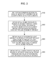
- the initial sound pressure in the region of interest is obtained without using a detection signal corresponding to the region of interest obtained by an acoustic wave detection element whose certain sensitive region set in S100 does not include the region of interest. Thereafter, data regarding the initial sound pressure is stored in the memory of the signal processing apparatus 40.
- the initial sound pressure obtaining module 42 obtains the initial sound pressure P 0 '(r T ) represented by the expression (4) by reconfiguring an image without using, among the detection signals P d1 (r T ), P d2 (r T ), and P d3 (r T ), the detection signal P d1 (r T ) corresponding to the region of interest obtained by the acoustic wave detection element e1.
- an image reconfiguration algorithm executed by the initial sound pressure obtaining module 42 for example, reverse projection in a time domain or a Fourier domain normally used in a tomography technology or the like may be used.
- a certain sensitive region is included in at least a part of the region of interest, it can be said that the region of interest is included in the certain sensitive region.
- not using a detection signal is a concept including not using a detection signal at all and not using a detection signal essentially when the initial sound pressure is obtained.
- the value of the integrated light intensity in the region of interest is obtained without using the value of the light intensity in the region of interest corresponding to the detection signal that has not been used in S200. Thereafter, data regarding the value of the integrated light intensity is stored in the memory of the signal processing apparatus 40.
- the light intensity obtaining module 43 obtains a value of the integrated light intensity ⁇ '(r T ) in the region of interest represented by an expression (6) without using, among the values of the light intensity ⁇ 1 (r T ), ⁇ 2 (r T ), and ⁇ 3 (r T ), the value of the light intensity ⁇ 1 (r T ) in the region of interest corresponding to the detection signal P d1 (r T ) that has not been used by the initial sound pressure obtaining module 42.
- the light intensity obtaining module 43 obtains the value of the integrated light intensity in the region of interest using the values of the light intensity in the region of interest corresponding to detection signals used when the initial sound pressure obtaining module 42 has calculated the initial sound pressure.
- not using a value of the light intensity is a concept including not using a value of the light intensity at all and not using a value of the light intensity essentially when the value of the integrated light intensity is obtained.
- the light intensity obtaining module 43 may obtain a value obtained by multiplying the number of detection signals used when the initial sound pressure obtaining module 42 has obtained the initial sound pressure by the light intensity that has reached the region of interest 33 as the value of the integrated light intensity in the region of interest 33.
- the value of the integrated light intensity obtained in such a manner is treated as the value of the integrated light intensity obtained without using a value of the light intensity.
- the absorption coefficient as an optical characteristic value in the region of interest is obtained using the initial sound pressure in the region of interest obtained in S200 and the value of the integrated light intensity in the region of interest obtained in S300.
- the optical characteristic value obtaining module 44 applies the initial sound pressure P 0 '(r T ) represented by the expression (3) and the value of the integrated light intensity ⁇ '(r T ) represented by the expression (6) to the expression (1). In doing so, an absorption coefficient ⁇ a (r T ) in the region of interest 33 represented by the expression (7) is obtained.
- the Grueneisen coefficient ⁇ 1.
- an absorption coefficient in which an error due to noise is small and whose quantativity is high can be obtained by, with respect to an acoustic wave detection element whose certain sensitive region does not include the region of interest, not using a detection signal corresponding to the region of interest obtained by the acoustic wave detection element and a value of the light intensity in the region of interest corresponding to the detection signal.
- an absorption coefficient for each wavelength may be obtained, instead.
- oxygen saturation as an optical characteristic value may be obtained.
- a program including the above steps may be executed by the signal processing apparatus 40 as a computer.
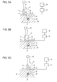
- Figs. 3A to 3C are schematic diagrams of a subject information obtaining apparatus according to the present embodiment.
- the subject information obtaining apparatus includes an acoustic wave detector 20 including a single acoustic wave detection element.
- a detector moving mechanism 21 for moving the subject 30 and the acoustic wave detector 20 relatively to each other is included.
- the detector moving mechanism 21 can detect the photoacoustic wave at a plurality of positions by moving the acoustic wave detector 20 including the single acoustic wave detection element in a right direction of the paper.
- the acoustic wave detection element at positions illustrated in Figs. 3A, 3B, and 3C is denoted by e1, e2, and e3, respectively.
- triangular regions indicated by lines represent a certain sensitive region corresponding to the acoustic wave detection element.
- a plurality of acoustic wave detection elements refer to an acoustic wave detection element that can detect the photoacoustic wave at a plurality of positions. That is, as in the present embodiment, an acoustic wave detection element that can detect the photoacoustic wave at a plurality of positions by moving the acoustic wave detector 20 is also referred to as a plurality of acoustic wave detection elements.
- the subject information obtaining apparatus is provided with an optical moving mechanism 13 that moves the optical system 11 in order to move the radiation light 12.
- the acoustic wave detector 20 and the radiation light 12 are moved in synchronization with each other.
- the radiation light 12 is constantly radiated onto the certain sensitive region (triangular region) corresponding to the acoustic wave detection element, thereby making it possible to constantly obtain a detection signal whose S/N is high.
- the region of interest 33 is not included in the certain sensitive region corresponding to the acoustic wave detection element e1. Therefore, the initial sound pressure obtaining module 42 obtains the initial sound pressure in the region of interest 33 without using a detection signal corresponding to the region of interest 33 obtained by the acoustic wave detection element e1. Thereafter, the light intensity obtaining module 43 obtains the value of the integrated light intensity in the region of interest 33 without using a value of the light intensity in the region of interest 33 corresponding to the detection signal that has not been used to obtain the initial sound pressure.
- the optical characteristic value obtaining module 44 obtains the absorption coefficient in the region of interest 33 represented by the expression (7) using the initial sound pressure and the value of the integrated light intensity. By obtaining the absorption coefficient in such a manner, in the present embodiment, too, the absorption coefficient can be accurately obtained.
- the absorption coefficient is obtained without using, with respect to an acoustic wave detection element whose certain sensitive region does not include the region of interest, a detection signal corresponding to the region of interest obtained by the acoustic wave detection element and a value of the light intensity in the region of interest corresponding to the detection signal.
- the absorption coefficient is obtained while reducing the detection signal and the value of the light intensity in the region of interest corresponding to the detection signal.
- a method for obtaining information regarding a subject according to the present embodiment will be described hereinafter using the subject information obtaining apparatus illustrated in Fig. 1 .
- the initial sound pressure obtaining module 42 multiplies the detection signal corresponding to the region of interest 33 obtained by the acoustic wave detection element e1 whose certain sensitive region does not include the region of interest 33 by a first reduction coefficient.
- the initial sound pressure obtaining module 42 then obtains the initial sound pressure in the region of interest 33 using the detection signal multiplied by the first reduction coefficient, too.
- the initial sound pressure can be obtained while reducing the detection signal, whose S/N is low. Therefore, initial sound pressure in which an error due to noise is small can be obtained.
- the light intensity obtaining module 43 multiplies, by a second reduction coefficient, the value of the light intensity in the region of interest 33 corresponding to the detection signal multiplied by the first reduction coefficient.
- the light intensity obtaining module 43 then obtains the value of the integrated light intensity in the region of interest 33 using the value of the light intensity multiplied by the second reduction coefficient, too.
- the optical characteristic value obtaining module 44 obtains the absorption coefficient in the region of interest 33 using the initial sound pressure obtained by the initial sound pressure obtaining module 42 and the value of the integrated light intensity obtained by the light intensity obtaining module 43.
- the absorption coefficient can be accurately obtained.
- first reduction coefficient and the second reduction coefficient are values smaller than 1.
- another reduction coefficient may be set in accordance with the region of interest.
- the same value is a concept including the completely same value and values that become essentially the same when the absorption coefficient is obtained.
- the present invention can be applied to a subject information obtaining apparatus illustrated in Figs. 4A to 4C and a subject information obtaining apparatus illustrated in Figs. 5A to 5C .
- the subject information obtaining apparatus illustrated in Figs. 4A to 4C can detect the photoacoustic wave at a plurality of positions by rotatively moving the acoustic wave detector 20 around the subject 30 using the detector moving mechanism 21.
- the subject 30 in order to establish acoustic impedance matching between the subject 30 and the acoustic wave detector 20, the subject 30 is immersed in water 80 that fills a water tank 81.
- a subject moving mechanism 34 that moves the subject 30 is included.
- a state illustrated in Fig. 4A changes to a state illustrated in Fig. 4B by moving the subject in a lower direction of the paper using the subject moving mechanism 34.
- the state illustrated in Fig. 4B changes to a state illustrated in Fig. 4C by moving the acoustic wave detector 20 using the detector moving mechanism 21.
- the acoustic wave detection element in the states illustrated in Figs. 4A, 4B, and 4C is denoted by e1, e2, and e3, respectively.
- triangular regions indicated by broken lines represent a certain sensitive region corresponding to the acoustic wave detection element.
- the subject information obtaining apparatus illustrated in Figs. 5A to 5C is provided with the acoustic wave detector 20 and the optical system 11 stored in a single housing 70.
- the housing 70 is provided with a hand-held mechanism 71, and the operator can move the housing 70 by grasping the hand-held mechanism 71.
- the acoustic wave detection element can detect the photoacoustic wave at a plurality of positions.
- the acoustic wave detection element detects the photoacoustic wave while the operator is moving the housing 70 in a right direction of the paper by grasping the hand-held mechanism 71.
- acoustic wave detection element in states illustrated in Figs. 5A, 5B, and 5C is denoted by e1, e2, and e3, respectively.
- triangular regions indicated by broken lines represent a certain sensitive region corresponding to the acoustic wave detection element.
- the acoustic wave detector 20 is moved not mechanically but the housing 70 is arbitrarily moved by the operator by grasping the hand-held mechanism 71. Therefore, the positional relationship between the acoustic wave detector 20 and the region of interest 33 when the photoacoustic wave 32 has been detected cannot be identified.
- the housing 70 includes a position detector 72 for detecting the position of the housing 70, that is, the positions of the acoustic wave detector 20 and the optical system 11 stored in the housing 70.
- the signal processing apparatus 40 can obtain the absorption coefficient in the region of interest 33 using the method for obtaining information regarding a subject described in the first and second embodiments or the method for obtaining information regarding a subject described in the third embodiment. By obtaining the absorption coefficient in such a manner, in the present embodiment, too, the absorption coefficient can be accurately obtained.
- the light source 10 includes a light source that can generate pulse light of 5 nanoseconds to 50 nanoseconds.
- a laser from which a large output can be obtained is preferable, but a light-emitting diode may be used instead of the laser.
- the laser one of various lasers such as a solid-state laser, a gas laser, a dye laser, and a semiconductor laser may be used.
- a Ti:Sa laser excited by Nd:YAG or an alexandrite laser that has a large output and whose wavelength can be continuously changed is used.
- a plurality of single-wavelength lasers having different wavelengths may be included, instead.
- the pulse light emitted from the light source 10 is guided to the subject while being processed in such a way as to have a desired optical distribution shape typically by optical components such as lenses and mirrors, but it is also possible to transmit the pulse light using an optical waveguide such as an optical fiber.
- the optical system 11 is, for example, a mirror that reflects light, a lens that collects or spreads light or changes the shape of light, a diffusion plate that diffuses light, and the like.
- Such optical components may be any components insofar as the pulse light emitted from the light source is radiated onto the subject in a desired shape.
- the light is spread to a certain area compared to that the light is collected by a lens, in terms of the security of the subject and an increase in a diagnostic range.
- an optical moving mechanism may be provided in the optical system 11 in order to move the radiation light.
- the acoustic wave detector 20 which is a detector that detects a photoacoustic wave generated on a surface of and an inside of the subject using light, detects an acoustic wave and converts the acoustic wave into an electrical signal that is an analog signal.
- the acoustic wave detector 20 will also be referred to simply as a probe or a transducer hereinafter. Any type of acoustic wave detector such as a transducer using a piezoelectric phenomenon, a transducer using optical resonance, or a transducer using changes in capacitance may be used insofar as the transducer can detect photoacoustic wave signals.
- the acoustic wave detector 20 includes a plurality of acoustic wave detection elements.
- a photoacoustic wave can be detected at a plurality of positions.
- an acoustic wave can be simultaneously detected at a plurality of positions, thereby reducing detection time and an effect such as vibration of the subject.
- the acoustic wave detector 20 may be configured such that the acoustic wave detector 20 can be mechanically moved by the detector moving mechanism 21.
- a hand-held mechanism that is grasped by the operator in order to arbitrarily move the acoustic wave detector 20 may also be included.
- the signal collector 47 that amplifies an electrical signal obtained by the acoustic wave detector 20 and that converts the electrical signal from an analog signal to a digital signal is included.
- the signal collector 47 is typically configured by an amplifier, an A/D convertor, an FPGA (Field Programmable Gate Array) chip, and the like.
- the plurality of signals can be simultaneously processed. Accordingly, the time until an image is formed can be reduced.
- the "detection signal” herein is a concept including both an analog signal output from the acoustic wave detector 20 and a digital signal obtained by AD conversion by the signal collector 47.
- the signal processing apparatus 40 obtains an optical characteristic value inside the subject by performing reconfiguration of an image or the like.
- a workstation or the like is typically used, and a process for reconfiguring an image or the like is typically performed by software that has been programmed in advance.
- the software used in the workstation includes the setting module 41, the initial sound pressure obtaining module 42, the light intensity obtaining module 43, the optical characteristic value obtaining module 44, and the like.
- each module may be provided as a separate piece of hardware.
- the pieces of hardware as a whole may be used as the signal processing apparatus 40.
- the signal collector 47 and the signal processing apparatus 40 may be integrated with each other depending on the case.
- an optical characteristic value of the subject can be generated not by a software process such as one performed in the workstation but by a hardware process.
Landscapes
- Life Sciences & Earth Sciences (AREA)
- Health & Medical Sciences (AREA)
- Physics & Mathematics (AREA)
- Molecular Biology (AREA)
- Animal Behavior & Ethology (AREA)
- Pathology (AREA)
- Engineering & Computer Science (AREA)
- Biomedical Technology (AREA)
- Heart & Thoracic Surgery (AREA)
- Medical Informatics (AREA)
- Acoustics & Sound (AREA)
- Surgery (AREA)
- Biophysics (AREA)
- General Health & Medical Sciences (AREA)
- Public Health (AREA)
- Veterinary Medicine (AREA)
- Ultra Sonic Daignosis Equipment (AREA)
- Investigating Or Analyzing Materials By The Use Of Ultrasonic Waves (AREA)
- Breeding Of Plants And Reproduction By Means Of Culturing (AREA)
- Pharmaceuticals Containing Other Organic And Inorganic Compounds (AREA)
Applications Claiming Priority (1)
| Application Number | Priority Date | Filing Date | Title |
|---|---|---|---|
| PCT/JP2012/050914 WO2013108375A1 (fr) | 2012-01-18 | 2012-01-18 | Dispositif d'acquisition d'informations sur un sujet et procédé d'acquisition d'informations sur un sujet |
Publications (2)
| Publication Number | Publication Date |
|---|---|
| EP2805676A1 true EP2805676A1 (fr) | 2014-11-26 |
| EP2805676A4 EP2805676A4 (fr) | 2015-09-02 |
Family
ID=48798824
Family Applications (1)
| Application Number | Title | Priority Date | Filing Date |
|---|---|---|---|
| EP12866220.2A Withdrawn EP2805676A4 (fr) | 2012-01-18 | 2012-01-18 | Dispositif d'acquisition d'informations sur un sujet et procédé d'acquisition d'informations sur un sujet |
Country Status (7)
| Country | Link |
|---|---|
| US (2) | US20130197343A1 (fr) |
| EP (1) | EP2805676A4 (fr) |
| JP (1) | JP5871958B2 (fr) |
| CN (1) | CN104053402B (fr) |
| BR (1) | BR112014017377A8 (fr) |
| RU (1) | RU2602718C2 (fr) |
| WO (1) | WO2013108375A1 (fr) |
Families Citing this family (7)
| Publication number | Priority date | Publication date | Assignee | Title |
|---|---|---|---|---|
| JP2013255585A (ja) * | 2012-06-11 | 2013-12-26 | Canon Inc | 被検体情報取得装置、および、光音響プローブ |
| JP6358735B2 (ja) | 2014-02-26 | 2018-07-18 | オリンパス株式会社 | 光音響顕微鏡装置 |
| JP6452314B2 (ja) * | 2014-05-14 | 2019-01-16 | キヤノン株式会社 | 光音響装置、信号処理方法、及びプログラム |
| JP5948527B1 (ja) * | 2014-12-22 | 2016-07-06 | オリンパス株式会社 | 超音波観測装置、超音波観測装置の作動方法および超音波観測装置の作動プログラム |
| JP2017070385A (ja) * | 2015-10-06 | 2017-04-13 | キヤノン株式会社 | 被検体情報取得装置およびその制御方法 |
| JP2018117709A (ja) * | 2017-01-23 | 2018-08-02 | キヤノン株式会社 | 光音響装置 |
| JP6537540B2 (ja) * | 2017-01-25 | 2019-07-03 | キヤノン株式会社 | 処理装置 |
Family Cites Families (16)
| Publication number | Priority date | Publication date | Assignee | Title |
|---|---|---|---|---|
| EP1585440A1 (fr) * | 2003-01-13 | 2005-10-19 | Glucon Inc. | Procede et appareil de test photoacoustique |
| US8317702B2 (en) * | 2003-06-20 | 2012-11-27 | U-Systems, Inc. | Full-field breast ultrasound system and architecture |
| US20060058670A1 (en) * | 2004-08-10 | 2006-03-16 | General Electric Company | Method and apparatus for ultrasound spatial compound imaging with adjustable aperture controls |
| US7806122B2 (en) * | 2007-05-11 | 2010-10-05 | Medtronic, Inc. | Septum port locator system and method for an implantable therapeutic substance delivery device |
| JP4739363B2 (ja) * | 2007-05-15 | 2011-08-03 | キヤノン株式会社 | 生体情報イメージング装置、生体情報の解析方法、及び生体情報のイメージング方法 |
| AU2008325237B2 (en) * | 2007-11-05 | 2014-05-01 | Biosensor, Inc. | Optical sensor for determining the concentration of an analyte |
| JP5541662B2 (ja) * | 2008-09-12 | 2014-07-09 | キヤノン株式会社 | 被検体情報取得装置およびその制御方法 |
| JP2010088627A (ja) * | 2008-10-07 | 2010-04-22 | Canon Inc | 生体情報処理装置および生体情報処理方法 |
| US20100094134A1 (en) * | 2008-10-14 | 2010-04-15 | The University Of Connecticut | Method and apparatus for medical imaging using near-infrared optical tomography combined with photoacoustic and ultrasound guidance |
| JP2011005042A (ja) * | 2009-06-26 | 2011-01-13 | Canon Inc | 光音響イメージング装置及び光音響イメージング方法 |
| US8862206B2 (en) * | 2009-11-12 | 2014-10-14 | Virginia Tech Intellectual Properties, Inc. | Extended interior methods and systems for spectral, optical, and photoacoustic imaging |
| JP5528083B2 (ja) * | 2009-12-11 | 2014-06-25 | キヤノン株式会社 | 画像生成装置、画像生成方法、及び、プログラム |
| JP5419727B2 (ja) * | 2010-01-22 | 2014-02-19 | キヤノン株式会社 | 画像形成方法及び音響波測定装置 |
| JP5393552B2 (ja) * | 2010-03-19 | 2014-01-22 | キヤノン株式会社 | 測定装置 |
| JP5777358B2 (ja) * | 2010-04-27 | 2015-09-09 | キヤノン株式会社 | 被検体情報取得装置及び信号処理方法 |
| JP5641773B2 (ja) * | 2010-04-28 | 2014-12-17 | キヤノン株式会社 | 測定装置 |
-
2012
- 2012-01-18 JP JP2013554144A patent/JP5871958B2/ja not_active Expired - Fee Related
- 2012-01-18 BR BR112014017377A patent/BR112014017377A8/pt not_active Application Discontinuation
- 2012-01-18 WO PCT/JP2012/050914 patent/WO2013108375A1/fr not_active Ceased
- 2012-01-18 RU RU2014133557/14A patent/RU2602718C2/ru active
- 2012-01-18 CN CN201280067433.8A patent/CN104053402B/zh not_active Expired - Fee Related
- 2012-01-18 EP EP12866220.2A patent/EP2805676A4/fr not_active Withdrawn
-
2013
- 2013-01-15 US US13/741,711 patent/US20130197343A1/en not_active Abandoned
-
2017
- 2017-09-08 US US15/699,790 patent/US20180028067A1/en not_active Abandoned
Also Published As
| Publication number | Publication date |
|---|---|
| RU2014133557A (ru) | 2016-03-10 |
| US20180028067A1 (en) | 2018-02-01 |
| US20130197343A1 (en) | 2013-08-01 |
| JP5871958B2 (ja) | 2016-03-01 |
| WO2013108375A1 (fr) | 2013-07-25 |
| RU2602718C2 (ru) | 2016-11-20 |
| BR112014017377A8 (pt) | 2017-07-04 |
| BR112014017377A2 (pt) | 2017-06-13 |
| CN104053402A (zh) | 2014-09-17 |
| EP2805676A4 (fr) | 2015-09-02 |
| JPWO2013108375A1 (ja) | 2015-05-11 |
| WO2013108375A9 (fr) | 2014-06-19 |
| CN104053402B (zh) | 2017-04-19 |
Similar Documents
| Publication | Publication Date | Title |
|---|---|---|
| US20180028067A1 (en) | Subject information obtaining apparatus and method for obtaining information regarding subject | |
| EP2494923B1 (fr) | Dispositif photo-acoustique | |
| US10408799B2 (en) | Apparatus and method for photoacoustic imaging | |
| JP5693043B2 (ja) | 被検体情報取得装置、被検体情報取得方法 | |
| CN102131463B (zh) | 生物信息处理设备和生物信息处理方法 | |
| EP2533697B1 (fr) | Appareil d'imagerie photoacoustique et procédé d'imagerie photoacoustique | |
| EP2382917B2 (fr) | Appareil d'obtention de données d'affichage et procédé d'obtention de données d'affichage | |
| EP2638850B1 (fr) | Dispositif d'obtention d'informations d'un sujet, procédé d'obtention d'informations d'un sujet et programme | |
| EP2638851A1 (fr) | Dispositif et procédé d'obtention d'informations de sujet et programme | |
| US9116110B2 (en) | Object information acquiring apparatus and object information acquiring method | |
| US20130199300A1 (en) | Apparatus and method for obtaining object information and non-transitory computer-readable storage medium | |
| JP2013255707A (ja) | 被検体情報取得装置、および、光音響プローブ | |
| JP2014140718A (ja) | 被検体情報取得装置、表示方法、およびプログラム | |
| EP2647333A1 (fr) | Appareil d'obtention d'informations de sujet et procédé d'obtention d'informations de sujet | |
| JP6000728B2 (ja) | 被検体情報取得装置および被検体情報取得方法 | |
| EP2767223A1 (fr) | Appareil d'acquisition d'informations d'objet et son procédé de commande | |
| JP6168802B2 (ja) | 処理装置、処理方法、及びプログラム | |
| JP2013255585A (ja) | 被検体情報取得装置、および、光音響プローブ | |
| JP6084313B2 (ja) | 被検体情報取得装置及び被検体情報取得方法 | |
| JP6537540B2 (ja) | 処理装置 | |
| JP2017086173A (ja) | 被検体情報取得装置およびその制御方法 |
Legal Events
| Date | Code | Title | Description |
|---|---|---|---|
| PUAI | Public reference made under article 153(3) epc to a published international application that has entered the european phase |
Free format text: ORIGINAL CODE: 0009012 |
|
| 17P | Request for examination filed |
Effective date: 20140818 |
|
| AK | Designated contracting states |
Kind code of ref document: A1 Designated state(s): AL AT BE BG CH CY CZ DE DK EE ES FI FR GB GR HR HU IE IS IT LI LT LU LV MC MK MT NL NO PL PT RO RS SE SI SK SM TR |
|
| DAX | Request for extension of the european patent (deleted) | ||
| RA4 | Supplementary search report drawn up and despatched (corrected) |
Effective date: 20150803 |
|
| RIC1 | Information provided on ipc code assigned before grant |
Ipc: A61B 5/00 20060101AFI20150728BHEP |
|
| 17Q | First examination report despatched |
Effective date: 20181004 |
|
| GRAP | Despatch of communication of intention to grant a patent |
Free format text: ORIGINAL CODE: EPIDOSNIGR1 |
|
| INTG | Intention to grant announced |
Effective date: 20200102 |
|
| STAA | Information on the status of an ep patent application or granted ep patent |
Free format text: STATUS: THE APPLICATION HAS BEEN WITHDRAWN |
|
| 18W | Application withdrawn |
Effective date: 20200408 |