EP2805687A1 - Dispositif de commande d'une pièce à main dentaire - Google Patents
Dispositif de commande d'une pièce à main dentaire Download PDFInfo
- Publication number
- EP2805687A1 EP2805687A1 EP13738184.4A EP13738184A EP2805687A1 EP 2805687 A1 EP2805687 A1 EP 2805687A1 EP 13738184 A EP13738184 A EP 13738184A EP 2805687 A1 EP2805687 A1 EP 2805687A1
- Authority
- EP
- European Patent Office
- Prior art keywords
- rotation angle
- rotation
- motor
- dental handpiece
- load torque
- Prior art date
- Legal status (The legal status is an assumption and is not a legal conclusion. Google has not performed a legal analysis and makes no representation as to the accuracy of the status listed.)
- Granted
Links
- 210000004262 dental pulp cavity Anatomy 0.000 description 18
- 238000000034 method Methods 0.000 description 9
- 230000000717 retained effect Effects 0.000 description 3
- 238000005259 measurement Methods 0.000 description 2
- 238000004140 cleaning Methods 0.000 description 1
- 238000004590 computer program Methods 0.000 description 1
- 238000001514 detection method Methods 0.000 description 1
- 230000000694 effects Effects 0.000 description 1
- 230000002265 prevention Effects 0.000 description 1
Images



Classifications
-
- A—HUMAN NECESSITIES
- A61—MEDICAL OR VETERINARY SCIENCE; HYGIENE
- A61C—DENTISTRY; APPARATUS OR METHODS FOR ORAL OR DENTAL HYGIENE
- A61C5/00—Filling or capping teeth
- A61C5/40—Implements for surgical treatment of the roots or nerves of the teeth; Nerve needles; Methods or instruments for medication of the roots
- A61C5/42—Files for root canals; Handgrips or guiding means therefor
-
- A—HUMAN NECESSITIES
- A61—MEDICAL OR VETERINARY SCIENCE; HYGIENE
- A61C—DENTISTRY; APPARATUS OR METHODS FOR ORAL OR DENTAL HYGIENE
- A61C1/00—Dental machines for boring or cutting ; General features of dental machines or apparatus, e.g. hand-piece design
- A61C1/0007—Control devices or systems
- A61C1/0015—Electrical systems
- A61C1/003—Control of rotation of instrument
-
- A—HUMAN NECESSITIES
- A61—MEDICAL OR VETERINARY SCIENCE; HYGIENE
- A61C—DENTISTRY; APPARATUS OR METHODS FOR ORAL OR DENTAL HYGIENE
- A61C1/00—Dental machines for boring or cutting ; General features of dental machines or apparatus, e.g. hand-piece design
- A61C1/02—Dental machines for boring or cutting ; General features of dental machines or apparatus, e.g. hand-piece design characterised by the drive of the dental tools
- A61C1/06—Dental machines for boring or cutting ; General features of dental machines or apparatus, e.g. hand-piece design characterised by the drive of the dental tools with electric drive
-
- A—HUMAN NECESSITIES
- A61—MEDICAL OR VETERINARY SCIENCE; HYGIENE
- A61C—DENTISTRY; APPARATUS OR METHODS FOR ORAL OR DENTAL HYGIENE
- A61C1/00—Dental machines for boring or cutting ; General features of dental machines or apparatus, e.g. hand-piece design
- A61C1/08—Machine parts specially adapted for dentistry
- A61C1/18—Flexible shafts; Clutches or the like; Bearings or lubricating arrangements; Drives or transmissions
- A61C1/185—Drives or transmissions
- A61C1/186—Drives or transmissions with torque adjusting or limiting means
-
- A—HUMAN NECESSITIES
- A61—MEDICAL OR VETERINARY SCIENCE; HYGIENE
- A61C—DENTISTRY; APPARATUS OR METHODS FOR ORAL OR DENTAL HYGIENE
- A61C19/00—Dental auxiliary appliances
- A61C19/04—Measuring instruments specially adapted for dentistry
- A61C19/042—Measuring instruments specially adapted for dentistry for determining the position of a root apex
-
- A—HUMAN NECESSITIES
- A61—MEDICAL OR VETERINARY SCIENCE; HYGIENE
- A61C—DENTISTRY; APPARATUS OR METHODS FOR ORAL OR DENTAL HYGIENE
- A61C5/00—Filling or capping teeth
- A61C5/40—Implements for surgical treatment of the roots or nerves of the teeth; Nerve needles; Methods or instruments for medication of the roots
-
- F—MECHANICAL ENGINEERING; LIGHTING; HEATING; WEAPONS; BLASTING
- F04—POSITIVE - DISPLACEMENT MACHINES FOR LIQUIDS; PUMPS FOR LIQUIDS OR ELASTIC FLUIDS
- F04C—ROTARY-PISTON, OR OSCILLATING-PISTON, POSITIVE-DISPLACEMENT MACHINES FOR LIQUIDS; ROTARY-PISTON, OR OSCILLATING-PISTON, POSITIVE-DISPLACEMENT PUMPS
- F04C2270/00—Control; Monitoring or safety arrangements
- F04C2270/04—Force
- F04C2270/042—Force radial
- F04C2270/0421—Controlled or regulated
Definitions
- the present invention relates to an apparatus for controlling a dental handpiece to cut the root canals of teeth.
- Dental handpieces to cut the root canals of teeth have a configuration in which a cutting tool called a file is rotated by a motor.
- the file that cuts the root canals of teeth has a thin long form.
- a force in a twist direction is applied to the file, resulting in a problem that the file is easily broken.
- the file is rotated clockwise or counterclockwise through a desired first rotation angle, and subsequently rotated in a direction opposite to the first rotation angle through a second rotation angle.
- the first rotation angle is larger than the second rotation angle such that cut debris removed from the root canal is ejected upwardly from the surface of the root canal when the file is advanced in cleaning the root canal.
- Patent Literature 1 National Publication of International Patent Application, JP2003-504113A
- the first rotation angle and the second rotation angle are fixed to preset values, e.g., 120°C and 90°C, respectively. Therefore, even when a load is increased, the file continues to rotate up to the set angle, and the file sometimes bites into the root canal, thereby possibly causing breakage of the file.
- the present invention has been accomplished in view of the technical problem as described above, and an object thereof is to provide a dental handpiece control apparatus which can prevent a file that performs reciprocating rotation from biting into a root canal.
- a dental handpiece control apparatus includes: a rotation direction switching section that switches a polarity of a voltage applied to a motor, and thereby switches a rotation direction of the motor to forward rotation and backward rotation, the motor being incorporated in the dental handpiece to rotate a cutting tool (a file) mounted to the dental handpiece; and a control section that controls the switching of the voltage polarity by the rotation direction switching section based on a rotation angle ⁇ F for forward rotation and a rotation angle ⁇ R for backward rotation of the motor, the rotation angle ⁇ F and the rotation angle ⁇ R being associated with state information of the cutting tool.
- the rotation angle ⁇ F for forward rotation and the rotation angle ⁇ R for backward rotation are set to values with which the cutting tool in the state does not bite into a root canal, so that the cutting tool can be prevented from biting into the root canal.
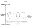
- the rotation angle ⁇ F for forward rotation means a rotation angle for forward rotation of one cycle
- the rotation angle ⁇ R for backward rotation means a rotation angle for backward rotation of one cycle
- the state information of the cutting tool may be a load torque of the motor.
- the control section preferably controls the switching of the voltage polarity by the rotation direction switching section based on the rotation angle ⁇ F and the rotation angle ⁇ R associated with the load torque. This is because the load torque of the motor can most notably indicate the biting of the cutting tool among the state information of the cutting tool.
- the load torque of the motor and the rotation angle ⁇ F , and the load torque of the motor and the rotation angle ⁇ R may be respectively in a proportional relationship.
- the rotation angle ⁇ F and the rotation angle ⁇ R may be different from each other with a reference value of the load torque of the motor as a boundary.
- the dental handpiece control apparatus which can prevent the cutting tool (the file) that performs reciprocating rotation from biting into the root canal can be provided.
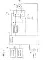
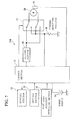
- a control apparatus 10 for a dental handpiece controls operation of a motor 20 that is incorporated in an unillustrated handpiece.
- the control apparatus 10 includes a control section 11, a display section 12, a setting section 13, a power supply 14, a driving section 15, a sensor 16, a relay (a rotation direction switching section) 17, and a current detecting resistor 18.
- the control section 11 is a computer unit including a CPU, a memory or the like.
- the display section 12 includes a monitor, an indicator lamp or the like for displaying information indicative of a rotation speed, a load torque as an operating state of the motor 20, or information used for setting the operation of the motor 20 or the like in the control section 11.
- the setting section 13 sets operating conditions such as a rotation speed, a torque, and a rotation angle of the motor 20 for the control section 11, and retains the set information. Particularly, the setting section 13 in the present embodiment retains set information regarding a rotation angle ⁇ F for forwardly rotating the motor 20, and a rotation angle ⁇ R for backwardly rotating the motor 20.
- the power supply 14 supplies electric power for allowing the handpiece control apparatus 10 and the motor 20 to work.
- the driving section 15 adjusts a voltage value applied to the motor 20 based on a command from the control section 11.
- the sensor 16 includes a hall element for detecting the rotation angle of the motor 20, and an encoder.
- the relay 17 switches the voltage polarity applied to the motor 20.
- the current detecting resistor 18 detects a current having passed through the relay 17, and converts a current (a motor current) having passed through the motor 20 to a voltage and feeds it back to the control section 11. Since a motor current and a load torque are in a proportional relationship in a DC motor, the control section 11 can measure the load toque of the motor 20 based on the fed-back voltage value.
- motor 20 any type of motor may be employed as the motor 20, for example, a brushless DC motor can be used.
- control apparatus 10 executes control as described below based on a preset computer program.
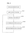
- step S101 voltage application to the motor 20 is started based on a command from the control section 11 (step S101).
- the control section 11 detects the rotation speed of the motor by the sensor 16, and adjusts the voltage applied to the motor 20 such that the detected value matches a set value (a set speed) of the rotation speed of the motor 20 set in advance in the setting section 13.
- the control section 11 also measures the load torque via the current detecting resistor 18 (step S103).
- the control section 11 sets the rotation angle ⁇ F for forwardly rotating the motor 20, and the rotation angle ⁇ R for backwardly rotating the motor 20 according to the load torque (step S105, S107).
- the rotation angles are set by referring to the information preliminarily retained in the setting section 13 as described above.
- One example of the information is described based on Figure 3 .
- the horizontal axis represents the load torque
- the vertical axis represents the rotation angle ⁇ .
- the rotation angle ⁇ F for the forward rotation and the rotation angle ⁇ R for the backward rotation are set in a proportional relationship such that the rotation angle ⁇ F becomes smaller as the load torque becomes larger, and conversely, the rotation angle ⁇ R becomes larger as the load torque becomes larger.
- the rotation angle ⁇ F e.g., 150°
- the rotation angle ⁇ R e.g., 30°
- the control section 11 switches the relay 17 based on the set rotation angle ⁇ F and the set rotation angle ⁇ R , to switch the polarity of the voltage applied to the motor 20 and forwardly and backwardly rotate the motor 20.
- a net rotation angle of a file (a cutting tool) through one cycle including the forward rotation and the backward rotation is a difference between the rotation angle ⁇ F and the rotation angle ⁇ R , i.e., ( ⁇ F - ⁇ R ).
- the rotation angle ⁇ F for the forward rotation and the rotation angle ⁇ R for the backward rotation are determined according to the magnitude of the load torque, so that biting of the file can be reduced to prevent breakage thereof.
- the present invention is not limited thereto.
- the example is described in a second embodiment.
- the control apparatus 10 has a similar basic configuration to that of the first embodiment, and differences from the first embodiment are mainly described below.
- the control apparatus 10 also measures the load torque as shown in Figure 5 similarly to the first embodiment (step S201, S203).
- a reference torque is preliminarily set and retained in the setting section 13, and the control section 11 compares the measured load torque with the reference torque (step S205).
- a first forward rotation angle ⁇ F1 and a first backward rotation angle ⁇ R1 are set (step S207, S209).
- a second forward rotation angle ⁇ F2 and a second backward rotation angle ⁇ R2 are set (step S211, S213).
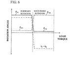
- first forward rotation angle ⁇ F1 the first backward rotation angle ⁇ R1 , the second forward rotation angle ⁇ F2 , and the second backward rotation angle ⁇ R2 is shown in Figure 6 .
- the second forward rotation angle ⁇ F2 is set to be smaller than the first forward rotation angle ⁇ F1
- the second backward rotation angle ⁇ R2 is set to be larger than the first backward rotation angle ⁇ R1 with a reference torque Tr as a boundary. That is, the second embodiment is similar to the first embodiment in that the forward rotation angle is increased when the load torque is small, and the backward rotation angle is increased when the load torque is large.
- the first forward rotation angle ⁇ F1 to the second backward rotation angle ⁇ R2 in Figure 5 are merely one example of the present invention, and various aspects, for example, in one of which the first backward rotation angle ⁇ R1 and the second backward rotation angle ⁇ R2 are set to the same value may be employed.
- the rotation angle ⁇ F for the forward rotation and the rotation angle ⁇ R for the backward rotation are also determined according to the magnitude of the load torque also in the second embodiment, so that biting of the file can be reduced to prevent breakage thereof.
- the second embodiment since the forward rotation angle is not reduced until the torque reaches the reference torque, it can be said that the second embodiment has a configuration in which cutting efficiency is more emphasized than in the first embodiment.
- the example of the first embodiment has a configuration in which prevention of the breakage of the file is emphasized.
- the control may be also executed by using both the information that the load torque and the rotation angle ⁇ F and the rotation angle ⁇ R are in a proportional relationship as in the first embodiment, and the information that the rotation angle ⁇ F and the rotation angle ⁇ R are identified based on the threshold value of the load torque as in the present embodiment.
- the present invention is not limited thereto, and a root apex position may be employed as the file state information as described below in a third embodiment.
- a control apparatus 210 includes a root apex position detecting section 21, and the handpiece (not shown) in which the motor 20 is controlled by the control apparatus 210 includes a root apex length measuring function.
- the handpiece having the function measures a distance from a root apex to (the tip of) the file by detecting a root apex position while performing root canal treatment. That is, the root apex is detected by inserting the file, which is provided with a function as a measuring electrode, into the root canal of a tooth, and applying an electrical measurement signal between the file and an oral electrode that is separately provided.
- the root apex position detecting section 21 provides a distance L between the measured root apex and the file to the control section 11.
- the setting section 13 retains information regarding the rotation angle ⁇ F for the forward rotation and the rotation angle ⁇ R for the backward rotation corresponding to the distance L.
- the example is shown in Figure 8 , in which the horizontal axis in Figure 3 is changed to the distance L.
- the control section 11 acquires the rotation angles (the rotation angle ⁇ F and the rotation angle ⁇ R for the backward rotation) corresponding to the measured distance L, i.e., the information shown in Figure 8 from the setting section 13, refers thereto, and controls the rotation of the motor 20 based on the rotation angles.
- the file tends to bite; however, in accordance with the third embodiment, since the rotation angle ⁇ F for the forward rotation and the rotation angle ⁇ R for the backward rotation are determined according to the distance L, biting of the file can be reduced to prevent breakage thereof.
- the rotation speed of the file may be used as the file state information, or the present invention also allows the rotation angle ⁇ F for the forward rotation and the rotation angle ⁇ R for the backward rotation to be set based on an instruction from an operator in view of the feel of the file during treatment performed by the operator.
- the presetting example in which the information that the file state information shown in Figures 3 , 6 , and 8 and the rotation angles are associated with each other is originally retained in the setting section 13 is described in the aforementioned embodiments, the information that the file state information and the rotation angles are associated with each other may be input to the setting section 13 by operator's manipulation, or the preset information may be also changed.
Landscapes
- Health & Medical Sciences (AREA)
- Oral & Maxillofacial Surgery (AREA)
- Life Sciences & Earth Sciences (AREA)
- General Health & Medical Sciences (AREA)
- Animal Behavior & Ethology (AREA)
- Veterinary Medicine (AREA)
- Public Health (AREA)
- Dentistry (AREA)
- Epidemiology (AREA)
- Engineering & Computer Science (AREA)
- Biomedical Technology (AREA)
- Neurosurgery (AREA)
- Neurology (AREA)
- Surgery (AREA)
- Nuclear Medicine, Radiotherapy & Molecular Imaging (AREA)
- Water Supply & Treatment (AREA)
- Biophysics (AREA)
- Dental Tools And Instruments Or Auxiliary Dental Instruments (AREA)
Applications Claiming Priority (2)
| Application Number | Priority Date | Filing Date | Title |
|---|---|---|---|
| JP2012005798 | 2012-01-16 | ||
| PCT/JP2013/000091 WO2013108602A1 (fr) | 2012-01-16 | 2013-01-11 | Dispositif de commande d'une pièce à main dentaire |
Publications (3)
| Publication Number | Publication Date |
|---|---|
| EP2805687A1 true EP2805687A1 (fr) | 2014-11-26 |
| EP2805687A4 EP2805687A4 (fr) | 2015-09-23 |
| EP2805687B1 EP2805687B1 (fr) | 2018-08-29 |
Family
ID=48799036
Family Applications (1)
| Application Number | Title | Priority Date | Filing Date |
|---|---|---|---|
| EP13738184.4A Active EP2805687B1 (fr) | 2012-01-16 | 2013-01-11 | Dispositif de commande d'une pièce à main dentaire |
Country Status (6)
| Country | Link |
|---|---|
| US (1) | US9827069B2 (fr) |
| EP (1) | EP2805687B1 (fr) |
| JP (1) | JP5665242B2 (fr) |
| KR (1) | KR101544331B1 (fr) |
| CN (1) | CN103717172B (fr) |
| WO (1) | WO2013108602A1 (fr) |
Cited By (4)
| Publication number | Priority date | Publication date | Assignee | Title |
|---|---|---|---|---|
| WO2016174572A1 (fr) * | 2015-04-29 | 2016-11-03 | Maillefer Instruments Holding Sàrl | Système et procédé pour former des dentistes à des techniques de traitement endodontique. |
| EP2851034B1 (fr) | 2013-09-20 | 2017-11-08 | J. Morita Manufacturing Corporation | Appareil de traitement dentaire |
| IT201600129110A1 (it) * | 2016-12-21 | 2018-06-21 | Cefla Soc Cooperativa | Manipolo per endodonzia |
| EP3653161A1 (fr) * | 2018-11-19 | 2020-05-20 | J. Morita Mfg. Corp. | Appareil de traitement dentaire et son procédé de commande |
Families Citing this family (11)
| Publication number | Priority date | Publication date | Assignee | Title |
|---|---|---|---|---|
| CN103379875B (zh) * | 2011-05-27 | 2015-05-13 | 株式会社中西 | 牙科用手机的控制装置 |
| JP5802149B2 (ja) * | 2012-02-24 | 2015-10-28 | 株式会社モリタ製作所 | 歯科用治療装置 |
| JP5870154B2 (ja) | 2013-09-20 | 2016-02-24 | 株式会社モリタ製作所 | 歯科用治療装置、およびその駆動方法 |
| JP2018108358A (ja) * | 2016-12-21 | 2018-07-12 | チェフラ エッセ.チ. | 歯内治療ハンドピース |
| CN106712586B (zh) * | 2017-03-08 | 2018-12-18 | 广州蓝鼎医疗器械有限公司 | 一种根管治疗仪马达转动控制方法 |
| JP7032340B2 (ja) | 2019-02-06 | 2022-03-08 | 株式会社モリタ製作所 | 歯科用治療装置およびその駆動方法 |
| CN110559091B (zh) * | 2019-09-29 | 2021-02-02 | 中国人民解放军陆军军医大学第一附属医院 | 具有辅助测距定深功能的牙科手机 |
| JP7405731B2 (ja) * | 2020-11-26 | 2023-12-26 | 株式会社モリタ製作所 | 歯科用治療装置、およびその制御方法 |
| KR102567583B1 (ko) * | 2021-03-29 | 2023-08-17 | (주)메타시스템즈 | 치과용 핸드피스의 모터 제어방법 |
| CN115804658A (zh) * | 2021-09-16 | 2023-03-17 | 桂林市啄木鸟医疗器械有限公司 | 根管治疗设备的机电控制系统及其切削控制方法和装置 |
| WO2024249984A1 (fr) * | 2023-06-02 | 2024-12-05 | Dentsply Sirona Inc. | Mouvement motorisé de va-et-vient pour limes endodontiques |
Family Cites Families (14)
| Publication number | Priority date | Publication date | Assignee | Title |
|---|---|---|---|---|
| JPS57180951A (en) | 1981-04-30 | 1982-11-08 | Kazutoshi Ishii | Apparatus for controlling positive and reverse rotation repeating motion of dental hand motor |
| JPS6211442A (ja) | 1985-03-08 | 1987-01-20 | 株式会社 モリタ製作所 | 歯科用マイクロモ−タの正逆転反復制御装置 |
| FR2684168B1 (fr) * | 1991-11-25 | 1994-04-01 | Distribution Mat Chirurgical | Lampe d'eclairage chirurgical avec moyen automatique de reglage de la concentration des rayons lumineux sur le champ operatoire. |
| JP3264607B2 (ja) * | 1995-07-28 | 2002-03-11 | 株式会社モリタ製作所 | 歯科用ハンドピースのモータ制御装置 |
| JP2003504113A (ja) | 1999-07-13 | 2003-02-04 | デンツプライ インターナショナル インコーポレーテッド | 歯内治療器具類用の回転ハンドピース |
| IT1314879B1 (it) * | 2000-11-30 | 2003-01-16 | Advanced Technology Res A T R | Procedimento di controllo dell'azionamento dell'utensile in undispositivo endodontico da fresatura, e dispositivo endodontico |
| JP3676753B2 (ja) * | 2001-05-02 | 2005-07-27 | 株式会社モリタ製作所 | 歯科用診療装置 |
| US8047842B2 (en) * | 2008-08-18 | 2011-11-01 | Johnson William B | Reciprocal reverse rotation endodontic file |
| WO2010066337A1 (fr) * | 2008-12-09 | 2010-06-17 | Vdw Gmbh | Dispositif endodontique et procédé pour le faire fonctionner |
| WO2010109464A2 (fr) * | 2009-03-24 | 2010-09-30 | Forum Engineering Technologies (96) Ltd. | Système de traitement endodontique |
| IT1396742B1 (it) | 2009-12-04 | 2012-12-14 | By Dental S R L | Dispositivo endodontico. |
| JP4916037B2 (ja) | 2010-07-02 | 2012-04-11 | 株式会社ナカニシ | 歯科用ハンドピースのモータ制御方法及び制御装置 |
| US20120225406A1 (en) * | 2011-03-03 | 2012-09-06 | Yared Ghassan | Endodontic tool and method |
| CN103379875B (zh) | 2011-05-27 | 2015-05-13 | 株式会社中西 | 牙科用手机的控制装置 |
-
2013
- 2013-01-11 JP JP2013554244A patent/JP5665242B2/ja active Active
- 2013-01-11 US US14/361,583 patent/US9827069B2/en not_active Expired - Fee Related
- 2013-01-11 CN CN201380002464.XA patent/CN103717172B/zh not_active Expired - Fee Related
- 2013-01-11 EP EP13738184.4A patent/EP2805687B1/fr active Active
- 2013-01-11 WO PCT/JP2013/000091 patent/WO2013108602A1/fr not_active Ceased
- 2013-01-11 KR KR1020147002405A patent/KR101544331B1/ko not_active Expired - Fee Related
Cited By (9)
| Publication number | Priority date | Publication date | Assignee | Title |
|---|---|---|---|---|
| EP2851034B1 (fr) | 2013-09-20 | 2017-11-08 | J. Morita Manufacturing Corporation | Appareil de traitement dentaire |
| WO2016174572A1 (fr) * | 2015-04-29 | 2016-11-03 | Maillefer Instruments Holding Sàrl | Système et procédé pour former des dentistes à des techniques de traitement endodontique. |
| RU2714625C2 (ru) * | 2015-04-29 | 2020-02-18 | Дентсплай Сирона, Инк. | Эндодонтическое устройство и способ содействия обучению стоматологов заданной технике эндодонтического лечения (варианты) |
| EP3288487B1 (fr) | 2015-04-29 | 2020-07-22 | Dentsply Sirona Inc. | Système et procédé pour former des dentistes à des techniques de traitement endodontique. |
| US11170665B2 (en) | 2015-04-29 | 2021-11-09 | Dentsply Sirona Inc. | System and method for training dentists in endodontic treatment techniques |
| IT201600129110A1 (it) * | 2016-12-21 | 2018-06-21 | Cefla Soc Cooperativa | Manipolo per endodonzia |
| EP3338728A1 (fr) * | 2016-12-21 | 2018-06-27 | Cefla Societa' Cooperativa | Instrument endodontique |
| EP3653161A1 (fr) * | 2018-11-19 | 2020-05-20 | J. Morita Mfg. Corp. | Appareil de traitement dentaire et son procédé de commande |
| US11925516B2 (en) | 2018-11-19 | 2024-03-12 | J. Morita Mfg. Corp. | Dental treatment apparatus and method of driving the same |
Also Published As
| Publication number | Publication date |
|---|---|
| US9827069B2 (en) | 2017-11-28 |
| KR101544331B1 (ko) | 2015-08-12 |
| JPWO2013108602A1 (ja) | 2015-05-11 |
| JP5665242B2 (ja) | 2015-02-04 |
| CN103717172B (zh) | 2016-08-24 |
| CN103717172A (zh) | 2014-04-09 |
| KR20140043456A (ko) | 2014-04-09 |
| EP2805687B1 (fr) | 2018-08-29 |
| EP2805687A4 (fr) | 2015-09-23 |
| US20140322669A1 (en) | 2014-10-30 |
| WO2013108602A1 (fr) | 2013-07-25 |
Similar Documents
| Publication | Publication Date | Title |
|---|---|---|
| EP2805687B1 (fr) | Dispositif de commande d'une pièce à main dentaire | |
| TWI486152B (zh) | Control devices for hand - held electric drill for dental use | |
| CN102427774B (zh) | 牙科用机头的马达控制方法及控制装置 | |
| CN110248619B (zh) | 根管治疗装置 | |
| JP5870154B2 (ja) | 歯科用治療装置、およびその駆動方法 | |
| JP6193697B2 (ja) | 歯科用治療装置 | |
| EP2753263B1 (fr) | Pièce à main dentaire | |
| CN110944596B (zh) | 牙科用治疗装置及其驱动方法 | |
| CN113395946B (zh) | 牙科用治疗装置及其驱动方法 | |
| CN111195159A (zh) | 牙科治疗装置及其驱动方法 | |
| KR102122659B1 (ko) | 치과용 핸드피스의 모터 제어 방법 및 장치 | |
| JP7586855B2 (ja) | 歯科用治療装置 | |
| JP2019195719A5 (fr) |
Legal Events
| Date | Code | Title | Description |
|---|---|---|---|
| PUAI | Public reference made under article 153(3) epc to a published international application that has entered the european phase |
Free format text: ORIGINAL CODE: 0009012 |
|
| 17P | Request for examination filed |
Effective date: 20140526 |
|
| AK | Designated contracting states |
Kind code of ref document: A1 Designated state(s): AL AT BE BG CH CY CZ DE DK EE ES FI FR GB GR HR HU IE IS IT LI LT LU LV MC MK MT NL NO PL PT RO RS SE SI SK SM TR |
|
| DAX | Request for extension of the european patent (deleted) | ||
| RA4 | Supplementary search report drawn up and despatched (corrected) |
Effective date: 20150826 |
|
| RIC1 | Information provided on ipc code assigned before grant |
Ipc: A61C 19/04 20060101ALI20150820BHEP Ipc: A61C 5/02 20060101ALI20150820BHEP Ipc: A61C 1/06 20060101AFI20150820BHEP Ipc: A61C 1/00 20060101ALI20150820BHEP |
|
| STAA | Information on the status of an ep patent application or granted ep patent |
Free format text: STATUS: EXAMINATION IS IN PROGRESS |
|
| 17Q | First examination report despatched |
Effective date: 20171117 |
|
| GRAP | Despatch of communication of intention to grant a patent |
Free format text: ORIGINAL CODE: EPIDOSNIGR1 |
|
| RIC1 | Information provided on ipc code assigned before grant |
Ipc: A61C 1/06 20060101ALI20180320BHEP Ipc: A61C 1/08 20060101AFI20180320BHEP Ipc: A61C 19/04 20060101ALN20180320BHEP Ipc: A61C 5/40 20170101ALI20180320BHEP |
|
| STAA | Information on the status of an ep patent application or granted ep patent |
Free format text: STATUS: GRANT OF PATENT IS INTENDED |
|
| INTG | Intention to grant announced |
Effective date: 20180426 |
|
| GRAJ | Information related to disapproval of communication of intention to grant by the applicant or resumption of examination proceedings by the epo deleted |
Free format text: ORIGINAL CODE: EPIDOSDIGR1 |
|
| STAA | Information on the status of an ep patent application or granted ep patent |
Free format text: STATUS: EXAMINATION IS IN PROGRESS |
|
| REG | Reference to a national code |
Ref country code: DE Ref legal event code: R079 Ref document number: 602013042753 Country of ref document: DE Free format text: PREVIOUS MAIN CLASS: A61C0001060000 Ipc: A61C0001080000 |
|
| GRAR | Information related to intention to grant a patent recorded |
Free format text: ORIGINAL CODE: EPIDOSNIGR71 |
|
| GRAS | Grant fee paid |
Free format text: ORIGINAL CODE: EPIDOSNIGR3 |
|
| STAA | Information on the status of an ep patent application or granted ep patent |
Free format text: STATUS: GRANT OF PATENT IS INTENDED |
|
| GRAA | (expected) grant |
Free format text: ORIGINAL CODE: 0009210 |
|
| STAA | Information on the status of an ep patent application or granted ep patent |
Free format text: STATUS: THE PATENT HAS BEEN GRANTED |
|
| INTC | Intention to grant announced (deleted) | ||
| RIC1 | Information provided on ipc code assigned before grant |
Ipc: A61C 1/08 20060101AFI20180703BHEP Ipc: A61C 1/06 20060101ALI20180703BHEP Ipc: A61C 19/04 20060101ALN20180703BHEP Ipc: A61C 5/40 20170101ALI20180703BHEP |
|
| AK | Designated contracting states |
Kind code of ref document: B1 Designated state(s): AL AT BE BG CH CY CZ DE DK EE ES FI FR GB GR HR HU IE IS IT LI LT LU LV MC MK MT NL NO PL PT RO RS SE SI SK SM TR |
|
| INTG | Intention to grant announced |
Effective date: 20180724 |
|
| REG | Reference to a national code |
Ref country code: GB Ref legal event code: FG4D |
|
| REG | Reference to a national code |
Ref country code: CH Ref legal event code: EP |
|
| REG | Reference to a national code |
Ref country code: AT Ref legal event code: REF Ref document number: 1034238 Country of ref document: AT Kind code of ref document: T Effective date: 20180915 |
|
| REG | Reference to a national code |
Ref country code: IE Ref legal event code: FG4D |
|
| REG | Reference to a national code |
Ref country code: DE Ref legal event code: R096 Ref document number: 602013042753 Country of ref document: DE |
|
| REG | Reference to a national code |
Ref country code: NL Ref legal event code: MP Effective date: 20180829 |
|
| REG | Reference to a national code |
Ref country code: LT Ref legal event code: MG4D |
|
| PG25 | Lapsed in a contracting state [announced via postgrant information from national office to epo] |
Ref country code: GR Free format text: LAPSE BECAUSE OF FAILURE TO SUBMIT A TRANSLATION OF THE DESCRIPTION OR TO PAY THE FEE WITHIN THE PRESCRIBED TIME-LIMIT Effective date: 20181130 Ref country code: FI Free format text: LAPSE BECAUSE OF FAILURE TO SUBMIT A TRANSLATION OF THE DESCRIPTION OR TO PAY THE FEE WITHIN THE PRESCRIBED TIME-LIMIT Effective date: 20180829 Ref country code: NL Free format text: LAPSE BECAUSE OF FAILURE TO SUBMIT A TRANSLATION OF THE DESCRIPTION OR TO PAY THE FEE WITHIN THE PRESCRIBED TIME-LIMIT Effective date: 20180829 Ref country code: LT Free format text: LAPSE BECAUSE OF FAILURE TO SUBMIT A TRANSLATION OF THE DESCRIPTION OR TO PAY THE FEE WITHIN THE PRESCRIBED TIME-LIMIT Effective date: 20180829 Ref country code: BG Free format text: LAPSE BECAUSE OF FAILURE TO SUBMIT A TRANSLATION OF THE DESCRIPTION OR TO PAY THE FEE WITHIN THE PRESCRIBED TIME-LIMIT Effective date: 20181129 Ref country code: SE Free format text: LAPSE BECAUSE OF FAILURE TO SUBMIT A TRANSLATION OF THE DESCRIPTION OR TO PAY THE FEE WITHIN THE PRESCRIBED TIME-LIMIT Effective date: 20180829 Ref country code: IS Free format text: LAPSE BECAUSE OF FAILURE TO SUBMIT A TRANSLATION OF THE DESCRIPTION OR TO PAY THE FEE WITHIN THE PRESCRIBED TIME-LIMIT Effective date: 20181229 Ref country code: NO Free format text: LAPSE BECAUSE OF FAILURE TO SUBMIT A TRANSLATION OF THE DESCRIPTION OR TO PAY THE FEE WITHIN THE PRESCRIBED TIME-LIMIT Effective date: 20181129 Ref country code: RS Free format text: LAPSE BECAUSE OF FAILURE TO SUBMIT A TRANSLATION OF THE DESCRIPTION OR TO PAY THE FEE WITHIN THE PRESCRIBED TIME-LIMIT Effective date: 20180829 |
|
| REG | Reference to a national code |
Ref country code: AT Ref legal event code: MK05 Ref document number: 1034238 Country of ref document: AT Kind code of ref document: T Effective date: 20180829 |
|
| PG25 | Lapsed in a contracting state [announced via postgrant information from national office to epo] |
Ref country code: HR Free format text: LAPSE BECAUSE OF FAILURE TO SUBMIT A TRANSLATION OF THE DESCRIPTION OR TO PAY THE FEE WITHIN THE PRESCRIBED TIME-LIMIT Effective date: 20180829 Ref country code: LV Free format text: LAPSE BECAUSE OF FAILURE TO SUBMIT A TRANSLATION OF THE DESCRIPTION OR TO PAY THE FEE WITHIN THE PRESCRIBED TIME-LIMIT Effective date: 20180829 Ref country code: AL Free format text: LAPSE BECAUSE OF FAILURE TO SUBMIT A TRANSLATION OF THE DESCRIPTION OR TO PAY THE FEE WITHIN THE PRESCRIBED TIME-LIMIT Effective date: 20180829 |
|
| PG25 | Lapsed in a contracting state [announced via postgrant information from national office to epo] |
Ref country code: CZ Free format text: LAPSE BECAUSE OF FAILURE TO SUBMIT A TRANSLATION OF THE DESCRIPTION OR TO PAY THE FEE WITHIN THE PRESCRIBED TIME-LIMIT Effective date: 20180829 Ref country code: RO Free format text: LAPSE BECAUSE OF FAILURE TO SUBMIT A TRANSLATION OF THE DESCRIPTION OR TO PAY THE FEE WITHIN THE PRESCRIBED TIME-LIMIT Effective date: 20180829 Ref country code: AT Free format text: LAPSE BECAUSE OF FAILURE TO SUBMIT A TRANSLATION OF THE DESCRIPTION OR TO PAY THE FEE WITHIN THE PRESCRIBED TIME-LIMIT Effective date: 20180829 Ref country code: IT Free format text: LAPSE BECAUSE OF FAILURE TO SUBMIT A TRANSLATION OF THE DESCRIPTION OR TO PAY THE FEE WITHIN THE PRESCRIBED TIME-LIMIT Effective date: 20180829 Ref country code: EE Free format text: LAPSE BECAUSE OF FAILURE TO SUBMIT A TRANSLATION OF THE DESCRIPTION OR TO PAY THE FEE WITHIN THE PRESCRIBED TIME-LIMIT Effective date: 20180829 Ref country code: ES Free format text: LAPSE BECAUSE OF FAILURE TO SUBMIT A TRANSLATION OF THE DESCRIPTION OR TO PAY THE FEE WITHIN THE PRESCRIBED TIME-LIMIT Effective date: 20180829 Ref country code: PL Free format text: LAPSE BECAUSE OF FAILURE TO SUBMIT A TRANSLATION OF THE DESCRIPTION OR TO PAY THE FEE WITHIN THE PRESCRIBED TIME-LIMIT Effective date: 20180829 |
|
| PG25 | Lapsed in a contracting state [announced via postgrant information from national office to epo] |
Ref country code: SK Free format text: LAPSE BECAUSE OF FAILURE TO SUBMIT A TRANSLATION OF THE DESCRIPTION OR TO PAY THE FEE WITHIN THE PRESCRIBED TIME-LIMIT Effective date: 20180829 Ref country code: DK Free format text: LAPSE BECAUSE OF FAILURE TO SUBMIT A TRANSLATION OF THE DESCRIPTION OR TO PAY THE FEE WITHIN THE PRESCRIBED TIME-LIMIT Effective date: 20180829 Ref country code: SM Free format text: LAPSE BECAUSE OF FAILURE TO SUBMIT A TRANSLATION OF THE DESCRIPTION OR TO PAY THE FEE WITHIN THE PRESCRIBED TIME-LIMIT Effective date: 20180829 |
|
| REG | Reference to a national code |
Ref country code: DE Ref legal event code: R097 Ref document number: 602013042753 Country of ref document: DE |
|
| PLBE | No opposition filed within time limit |
Free format text: ORIGINAL CODE: 0009261 |
|
| STAA | Information on the status of an ep patent application or granted ep patent |
Free format text: STATUS: NO OPPOSITION FILED WITHIN TIME LIMIT |
|
| 26N | No opposition filed |
Effective date: 20190531 |
|
| PG25 | Lapsed in a contracting state [announced via postgrant information from national office to epo] |
Ref country code: MC Free format text: LAPSE BECAUSE OF FAILURE TO SUBMIT A TRANSLATION OF THE DESCRIPTION OR TO PAY THE FEE WITHIN THE PRESCRIBED TIME-LIMIT Effective date: 20180829 Ref country code: SI Free format text: LAPSE BECAUSE OF FAILURE TO SUBMIT A TRANSLATION OF THE DESCRIPTION OR TO PAY THE FEE WITHIN THE PRESCRIBED TIME-LIMIT Effective date: 20180829 |
|
| REG | Reference to a national code |
Ref country code: CH Ref legal event code: PL |
|
| PG25 | Lapsed in a contracting state [announced via postgrant information from national office to epo] |
Ref country code: LU Free format text: LAPSE BECAUSE OF NON-PAYMENT OF DUE FEES Effective date: 20190111 |
|
| REG | Reference to a national code |
Ref country code: BE Ref legal event code: MM Effective date: 20190131 |
|
| REG | Reference to a national code |
Ref country code: IE Ref legal event code: MM4A |
|
| PG25 | Lapsed in a contracting state [announced via postgrant information from national office to epo] |
Ref country code: BE Free format text: LAPSE BECAUSE OF NON-PAYMENT OF DUE FEES Effective date: 20190131 |
|
| PG25 | Lapsed in a contracting state [announced via postgrant information from national office to epo] |
Ref country code: CH Free format text: LAPSE BECAUSE OF NON-PAYMENT OF DUE FEES Effective date: 20190131 Ref country code: LI Free format text: LAPSE BECAUSE OF NON-PAYMENT OF DUE FEES Effective date: 20190131 |
|
| PG25 | Lapsed in a contracting state [announced via postgrant information from national office to epo] |
Ref country code: IE Free format text: LAPSE BECAUSE OF NON-PAYMENT OF DUE FEES Effective date: 20190111 |
|
| PG25 | Lapsed in a contracting state [announced via postgrant information from national office to epo] |
Ref country code: TR Free format text: LAPSE BECAUSE OF FAILURE TO SUBMIT A TRANSLATION OF THE DESCRIPTION OR TO PAY THE FEE WITHIN THE PRESCRIBED TIME-LIMIT Effective date: 20180829 |
|
| PG25 | Lapsed in a contracting state [announced via postgrant information from national office to epo] |
Ref country code: PT Free format text: LAPSE BECAUSE OF FAILURE TO SUBMIT A TRANSLATION OF THE DESCRIPTION OR TO PAY THE FEE WITHIN THE PRESCRIBED TIME-LIMIT Effective date: 20181229 Ref country code: MT Free format text: LAPSE BECAUSE OF NON-PAYMENT OF DUE FEES Effective date: 20190111 |
|
| PG25 | Lapsed in a contracting state [announced via postgrant information from national office to epo] |
Ref country code: CY Free format text: LAPSE BECAUSE OF FAILURE TO SUBMIT A TRANSLATION OF THE DESCRIPTION OR TO PAY THE FEE WITHIN THE PRESCRIBED TIME-LIMIT Effective date: 20180829 |
|
| PG25 | Lapsed in a contracting state [announced via postgrant information from national office to epo] |
Ref country code: HU Free format text: LAPSE BECAUSE OF FAILURE TO SUBMIT A TRANSLATION OF THE DESCRIPTION OR TO PAY THE FEE WITHIN THE PRESCRIBED TIME-LIMIT; INVALID AB INITIO Effective date: 20130111 |
|
| PG25 | Lapsed in a contracting state [announced via postgrant information from national office to epo] |
Ref country code: MK Free format text: LAPSE BECAUSE OF FAILURE TO SUBMIT A TRANSLATION OF THE DESCRIPTION OR TO PAY THE FEE WITHIN THE PRESCRIBED TIME-LIMIT Effective date: 20180829 |
|
| PGFP | Annual fee paid to national office [announced via postgrant information from national office to epo] |
Ref country code: DE Payment date: 20250120 Year of fee payment: 13 |
|
| PGFP | Annual fee paid to national office [announced via postgrant information from national office to epo] |
Ref country code: FR Payment date: 20250128 Year of fee payment: 13 |
|
| PGFP | Annual fee paid to national office [announced via postgrant information from national office to epo] |
Ref country code: GB Payment date: 20250123 Year of fee payment: 13 |