EP2806083A1 - Dispositif de fixation de plaques de matière synthétique sur des constructions ou des éléments de construction et procédé d'habillage d'éléments de construction ou de constructions avec des plaques de matière synthétique - Google Patents
Dispositif de fixation de plaques de matière synthétique sur des constructions ou des éléments de construction et procédé d'habillage d'éléments de construction ou de constructions avec des plaques de matière synthétique Download PDFInfo
- Publication number
- EP2806083A1 EP2806083A1 EP13002705.5A EP13002705A EP2806083A1 EP 2806083 A1 EP2806083 A1 EP 2806083A1 EP 13002705 A EP13002705 A EP 13002705A EP 2806083 A1 EP2806083 A1 EP 2806083A1
- Authority
- EP
- European Patent Office
- Prior art keywords
- base body
- component
- fastening
- plastic
- structures
- Prior art date
- Legal status (The legal status is an assumption and is not a legal conclusion. Google has not performed a legal analysis and makes no representation as to the accuracy of the status listed.)
- Granted
Links
Images
Classifications
-
- E—FIXED CONSTRUCTIONS
- E04—BUILDING
- E04F—FINISHING WORK ON BUILDINGS, e.g. STAIRS, FLOORS
- E04F13/00—Coverings or linings, e.g. for walls or ceilings
- E04F13/07—Coverings or linings, e.g. for walls or ceilings composed of covering or lining elements; Sub-structures therefor; Fastening means therefor
- E04F13/08—Coverings or linings, e.g. for walls or ceilings composed of covering or lining elements; Sub-structures therefor; Fastening means therefor composed of a plurality of similar covering or lining elements
- E04F13/0801—Separate fastening elements
- E04F13/0832—Separate fastening elements without load-supporting elongated furring elements between wall and covering elements
- E04F13/0833—Separate fastening elements without load-supporting elongated furring elements between wall and covering elements not adjustable
- E04F13/0841—Separate fastening elements without load-supporting elongated furring elements between wall and covering elements not adjustable the fastening elements engaging the outer surface of the covering elements, not extending through the covering
- E04F13/0842—Separate fastening elements without load-supporting elongated furring elements between wall and covering elements not adjustable the fastening elements engaging the outer surface of the covering elements, not extending through the covering specially adapted for thin sheet-like materials, e.g. sheet-metal or plastics
-
- E—FIXED CONSTRUCTIONS
- E04—BUILDING
- E04F—FINISHING WORK ON BUILDINGS, e.g. STAIRS, FLOORS
- E04F13/00—Coverings or linings, e.g. for walls or ceilings
- E04F13/07—Coverings or linings, e.g. for walls or ceilings composed of covering or lining elements; Sub-structures therefor; Fastening means therefor
- E04F13/21—Fastening means specially adapted for covering or lining elements
- E04F13/24—Hidden fastening means on the rear of the covering or lining elements
Definitions
- the invention relates to a device for fixing plastic sheets to components or structures, in particular to concrete components or concrete structures. Moreover, the invention relates to a method for lining components or structures with plastic plates, in particular concrete or concrete structures. Furthermore, the invention relates to a mounting kit for fixing plastic sheets to components or structures and a lining system for lining of components or structures.
- concrete protection plates made of plastic are known, with which the concrete components and structures are lined. With the plastic plates, the production of dense concrete pans and a permanent protection against corrosion and abrasion is possible.
- the EP 1 165 905 B1 describes a concrete protection plate made of thermoplastic material, which has a variety of anchoring elements.
- the plastic plate is positioned on the front side with formwork elements and poured on the back with concrete, the anchoring elements fix the plates in all directions.
- plastic plates are known that are not cast with concrete, but are positioned at a distance from the wall. These plastic plates need not have anchoring elements, but only on spacers to support the plates on the component or structure can. The resulting space between the lining and the component or structure can then serve to check the sealing system.
- plastic panels are penetrated by fasteners.
- fasteners there is a need for the later sealing of the penetrations as well as the risk of leakage in the area of the seals. Therefore, plastic panels are also glued to concrete components and structures.
- the smooth surface of the plastic plates does not enter into a permanent frictional connection with the concrete, there is a risk that the plastic plates will come loose over time.
- the invention is based on the object to simplify the attachment of plastic sheets to components or structures and the lining of components or structures with plastic sheets and to reduce the risk of leaks.
- the inventive device for fixing plastic sheets is characterized by a base body with a welding element, on the one hand allows a positive and / or non-positive connection with the component or structure and on the other hand a penetration-free attachment of the plastic plates, so that leakage at the junction between plastic plate and base body can not occur.
- the base body has an underside facing the component or structure and an upper side facing the plastic plate, wherein the base body consists of a thermoplastic material.
- the welding element is made of an electrically conductive material which is embedded in the base body at its upper side or fixed on the upper side of the base body. Consequently, the welding element can rest on the surface of the base body or be partially or completely embedded in the base body. Preferably, however, the welding element is at least partially embedded in the base body. For manufacturing reasons, it may be advantageous if the welding element is not poured during the injection molding in the base body, but after injection by subsequent melting of the Base body is partially embedded in the surface of the base body, that is thermally connected to the base body.
- the surface of the welding element of electrically conductive material may be flush with the surface of the base body or spaced from the surface of the base body.
- the arrangement of the welding element on the surface of the base body is crucial that only the upper, but not the lower portion of the base body melts during the induction welding process.
- the penetration-free connection between the plastic plate and the base body takes place in that an alternating electromagnetic field is generated, with which the welding element is brought to a temperature which is sufficiently high, so that the thermoplastic material of the base body melts.
- plastic plate and base body are thermally welded.
- This welding process is also known as induction welding.
- Base body and plastic plate are preferably made of materials that melt at the same temperature, preferably from the same plastic.
- the base body has at least one recess.
- the fastening device according to the invention simplifies the application and installation of the various lining systems. If the plastic plates are to be arranged to form a gap at a distance from the wall of the component or structure, the fastening devices according to the invention can secure the plastic plates secure. But even if the gap between plates and wall to be potted, the fastening devices according to the invention contribute to a simplification of the process, since the secure attachment of the plastic plates makes the use of formwork elements superfluous, where the plastic plates would otherwise have to support.
- the welding element is formed as a sheet at least partially embedded in the base body, which is often penetrated by the thermoplastic material of the base body.
- the welding element is a grid or mesh or web of one or more electrically conductive threads or wires.
- the welding element is a grid or braid or fabric of galvanized steel wires.
- the welding element can also be designed as a preferably flat coil.
- the base body is preferably formed as a body with a flat top and bottom, wherein the top forms a contact surface for the plastic plate and the bottom of a contact surface for the wall of the component or structure.
- the contact surface on the upper side is preferably larger than the contact surface on the underside, so that a sufficiently large area is available for the welded connection.
- the base body is a round body with an upper disc-shaped portion and a lower cylindrical portion, wherein the diameter of the disc-shaped portion is larger than the diameter of the cylindrical portion.
- the upper disc-shaped portion of the welding element is embedded, which melts the disk-shaped portion only in the upper area.
- a single fastener is sufficient for the attachment of the base body to the component or structure.
- a single fastener is sufficient.
- only one central recess is provided in the base body in a further particularly preferred embodiment.
- the central recess of the base body preferably has an upper cylindrical portion extending to the top of the base body and a lower cylindrical portion extending to the lower surface of the base body.
- the upper cylindrical portion preferably has a larger diameter than the lower cylindrical portion.
- the shoulder between the two cylindrical sections of the central recess forms a support for spacer elements, for example washers, which can be inserted into the cylindrical section.
- the height of the upper cylindrical portion of the recess has a length sufficient for the attachment means not to project beyond the surface of the base body.
- the fastening means for fastening the base body to the component or structure can be designed differently. In practice, threaded bolts or studs (studs) or threaded rods with nuts have proven to be advantageous. These fasteners can be anchored to the building or component with dowels.
- the device according to the invention can be provided in a fastening kit which, in addition to the fastening device, also comprises the fastening means and spacing elements.
- the attachment kit preferably comprises further spacers to compensate for tolerances between the base body and the structure.
- the spacers may be plastic discs of different thickness, which in a particularly preferred embodiment preferably have the same outer diameter as the outer diameter of the cylindrical lower portion of the base body.
- the spacers are provided with a radial slot or a recess, so that even after the attachment of the base body can later postpone the spacers laterally without having to loosen the base body again. It but is also possible to provide a spacer in the form of a preferably longitudinally slotted piece of pipe, which is shortened on site to the required length.
- the fastening kit according to the invention can also be provided as a lining system together with the plastic plates having on one side a plurality of projecting elements on which the plastic plates can be supported on the wall of the component or structure, so that formwork elements can be omitted.
- the protruding elements are designed as anchoring elements, which may have splaying elements preferably with undercuts to secure anchoring with the potting compound to ensure.
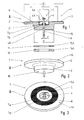
- Fig. 1 shows a section through the device according to the invention for the attachment of plastic plates to a component or structure.
- the fastening device has a rotationally symmetrical base body of a thermoplastic material, in particular PE.
- the base body can also consist of other thermoplastics, for example PP, PVC, PVDF and ECTFE.
- FIGS. 2 and 3 show the base body in a perspective view in the view from above and below.
- the base body 1 has a flat upper side 1A to which the plastic plate is attached, and a flat bottom 1B facing the wall of the component to which the base body is attached.
- the side facing the plastic plate is thus referred to as the top and the wall facing side as the bottom.
- the base body 1 has an upper disc-shaped portion 2, to which a lower cylindrical portion 3 is connected.
- the diameter a of the disk-shaped portion 2 is greater than the diameter b of the cylindrical portion 3.
- the disk-shaped portion is arcuately in the cylindrical portion over.
- the base body 1 has a central recess 4 for the passage of a fastening means 5, which in Fig. 1 is shown together with the base body.
- the Central recess 4 has an upper cylindrical portion 4A, to which a lower cylindrical portion 4B connects.
- the upper portion 4A has a larger inner diameter c than the inner diameter d of the lower cylindrical portion 4B.
- a single fastener 5 which has a percussion screw 6 and two spacers 7a and 7b.
- the inner diameter c of the upper portion 4A corresponds to the outer diameter of the larger spacer 7b.
- the length of the upper portion 4A is dimensioned such that the head 6a of the impact screw 6 is below the surface 1A of the base body when the base body is fixed to the wall of the component.
- a threaded screw or a threaded rod with a nut can be used to attach the base body.
- the plastic plate is attached to the upper side 1 A of the base body 1 by means of induction welding.
- the base body 1 has an induction welding element 8 made of an electrically conductive material, which is embedded in the base body at the top of the base body.
- the induction welding element 8 is a grid made of galvanized steel wire, which is cut in a ring and surrounds the central recess 4 of the base body 1 concentrically.
- the outer diameter e of the induction welding member 8 is larger than the outer diameter b of the cylindrical portion 3 and smaller than the outer diameter a of the disc-shaped portion 2 of the base body 1.
- the welding member 8 is inserted into the disk-shaped portion 2 of the base body 1 such that the upper side of the welding element with the top 1A of the base body closes or lies in a relatively small distance below the surface.
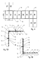
- Fig. 4 shows a schematic representation of the arrangement of rectangular plastic plates 10 (01, 02, 11 to 18 and 21, 22) for lining a cubic container. This is just an example arrangement.
- the plastic plates 10 have a flat, the container interior facing side 10A. On the back 10B, the plastic plates on projecting elements 9, which are designed as anchoring elements.
- the anchoring elements 9 have widening wing elements 9A, 9B, which are potted with a potting compound, such as concrete, screed or mortar 11.
- Fig. 6 shows a section through a portion of the potted with the potting compound 10 plastic plate in an enlarged view.
- the wall 12 of the container is freed from loose parts. Thereafter, positions are determined at which the fasteners A are attached to the wall 12 of the container. For this purpose, a corresponding grid is defined, each plastic plate 10 can be assigned a plurality of fasteners A. For large-area linings attachment points should also be at the points where several plastic plates 10 abut. Then holes 13 are drilled at the attachment points, are plugged into the dowels 14. Now, the fastening devices A can be screwed by means of tapping screws (nails), threaded screws or threaded rods with nuts, which are designated by the reference numeral 6, with the container wall 12.
- Fig. 1 shows a section through disk-shaped spacers 15, 16 of different thickness, which have an outer diameter corresponding to the outer diameter b of the cylindrical portion 3 of the base body 1.
- the spacers 15, 16 also have a central recess 15A, 16A.
- the disc-shaped spacers may also be provided with a radial slot or a recess or U-shaped, in order to later postpone the spacers can later, without the attachment of the base body would have to be solved.
- the plastic plates 10 are positioned, wherein for fixing the plates inner and outer mounting rails 16, 17 are used, which are inserted into the container and support the plastic plates in the corners and along the edges on the inside and outside. At the edges and corners of the plastic plates are welded by means of extruder welds 18 or pull wire welds.
- the attachment of the plastic plates 10 to the fasteners 1 by means of induction welding by means of induction welding.
- the induction welding devices suitable for this purpose are known to the person skilled in the art.
- the induction welding element 8 is brought to a sufficiently high temperature, so that the disk-shaped portion 2 of the base body is welded to the plastic plate. This creates a secure and penetration-free connection between plastic plate and base body, without the risk of leakage at the mounting points.
- the gap 20 between plastic plates 10 and container wall 12 can be filled with a potting compound 11, whereby the plastic plates are firmly connected to the container.
- the advantage of using the fasteners is that a shuttering for potting the cavities is not required because the plastic plates are fixed to the container wall.
- the fasteners ensure sufficient attachment for the plastic sheets.
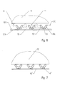
- the plastic plates need not have anchoring elements. It is sufficient that the projecting elements of the plastic plates form spacer elements, on which the plastic plates can be supported on the container wall.
- Fig. 7 shows a section through a portion of a plastic plate 10 'in an enlarged view, which is supported with spacers 9' on the container wall.
- the fasteners with which the plastic plate is attached to the container wall are in the partial view of Fig. 7 not shown.
- Concrete protection plates 10 for lining the component or building, which are fastened with the fastening devices according to the invention, are disclosed in US Pat EP 0 436 058 A1 and the EP 0 960 710 B 1 or EP 1 165 905 B1 described. But it can also be used other plastic plates that differ from these plates by the formation of the anchoring or spacer element.
Landscapes
- Engineering & Computer Science (AREA)
- Architecture (AREA)
- Civil Engineering (AREA)
- Structural Engineering (AREA)
- Joining Of Building Structures In Genera (AREA)
- Connection Of Plates (AREA)
Priority Applications (2)
| Application Number | Priority Date | Filing Date | Title |
|---|---|---|---|
| DK13002705.5T DK2806083T3 (da) | 2013-05-24 | 2013-05-24 | Indretning til fastgørelse af kunststofplader på bygninger eller komponenter samt fremgangsmåde til beklædning af komponenter eller bygninger med kunststofplader |
| EP13002705.5A EP2806083B1 (fr) | 2013-05-24 | 2013-05-24 | Dispositif de fixation de plaques de matière synthétique sur des constructions ou des éléments de construction et procédé d'habillage d'éléments de construction ou de constructions avec des plaques de matière synthétique |
Applications Claiming Priority (1)
| Application Number | Priority Date | Filing Date | Title |
|---|---|---|---|
| EP13002705.5A EP2806083B1 (fr) | 2013-05-24 | 2013-05-24 | Dispositif de fixation de plaques de matière synthétique sur des constructions ou des éléments de construction et procédé d'habillage d'éléments de construction ou de constructions avec des plaques de matière synthétique |
Publications (2)
| Publication Number | Publication Date |
|---|---|
| EP2806083A1 true EP2806083A1 (fr) | 2014-11-26 |
| EP2806083B1 EP2806083B1 (fr) | 2020-08-26 |
Family
ID=48534124
Family Applications (1)
| Application Number | Title | Priority Date | Filing Date |
|---|---|---|---|
| EP13002705.5A Active EP2806083B1 (fr) | 2013-05-24 | 2013-05-24 | Dispositif de fixation de plaques de matière synthétique sur des constructions ou des éléments de construction et procédé d'habillage d'éléments de construction ou de constructions avec des plaques de matière synthétique |
Country Status (2)
| Country | Link |
|---|---|
| EP (1) | EP2806083B1 (fr) |
| DK (1) | DK2806083T3 (fr) |
Cited By (2)
| Publication number | Priority date | Publication date | Assignee | Title |
|---|---|---|---|---|
| WO2024056994A1 (fr) | 2022-09-12 | 2024-03-21 | Valro Manufacturing Limited | Dispositif d'ancrage à membrane |
| WO2024252148A2 (fr) | 2023-06-06 | 2024-12-12 | Valro Manufacturing Limited | Élément de fixation de construction |
Citations (6)
| Publication number | Priority date | Publication date | Assignee | Title |
|---|---|---|---|---|
| EP0358164A2 (fr) * | 1988-09-07 | 1990-03-14 | Steuler-Industriewerke GmbH | Méthode pour installer une indication de fuite et/ou un espace d'isolation thermique entre une paroi et une plaque de revêtement de même que l'emploi de plaque de revêtement |
| EP0436058A1 (fr) | 1990-01-05 | 1991-07-10 | agru Alois Gruber G.m.b.H. | Procédé pour la fabrication de plaques en plastique avec des protubérances et plaque en plastique avec des protubérances |
| EP0556824A1 (fr) * | 1992-02-19 | 1993-08-25 | Lothar Mansfeld | Procédé pour l'application sur une paroi d'une feuille de protection; système muni d'une feuille de protection et de moyens d'ancrage |
| EP0960710B1 (fr) | 1998-04-28 | 2003-08-20 | Alois Gruber GmbH | Procédé et dispositif pour l'extrusion et le calendrage d'une plaque en matière plastique pourvue de protubérances d'ancrage ou formes similaires |
| EP1165905B1 (fr) | 2000-01-31 | 2004-10-27 | Alois Gruber GmbH | Plaque en matiere plastique, notamment pour revetir des pieces en beton |
| DE102009057680A1 (de) * | 2009-12-09 | 2011-06-16 | Steuler-Industriewerke Gmbh | Befestigungselement für ein chemisch, mechanisch und/oder thermisch belastetes Auskleidungselement sowie Auskleidungseinrichtung |
-
2013
- 2013-05-24 EP EP13002705.5A patent/EP2806083B1/fr active Active
- 2013-05-24 DK DK13002705.5T patent/DK2806083T3/da active
Patent Citations (6)
| Publication number | Priority date | Publication date | Assignee | Title |
|---|---|---|---|---|
| EP0358164A2 (fr) * | 1988-09-07 | 1990-03-14 | Steuler-Industriewerke GmbH | Méthode pour installer une indication de fuite et/ou un espace d'isolation thermique entre une paroi et une plaque de revêtement de même que l'emploi de plaque de revêtement |
| EP0436058A1 (fr) | 1990-01-05 | 1991-07-10 | agru Alois Gruber G.m.b.H. | Procédé pour la fabrication de plaques en plastique avec des protubérances et plaque en plastique avec des protubérances |
| EP0556824A1 (fr) * | 1992-02-19 | 1993-08-25 | Lothar Mansfeld | Procédé pour l'application sur une paroi d'une feuille de protection; système muni d'une feuille de protection et de moyens d'ancrage |
| EP0960710B1 (fr) | 1998-04-28 | 2003-08-20 | Alois Gruber GmbH | Procédé et dispositif pour l'extrusion et le calendrage d'une plaque en matière plastique pourvue de protubérances d'ancrage ou formes similaires |
| EP1165905B1 (fr) | 2000-01-31 | 2004-10-27 | Alois Gruber GmbH | Plaque en matiere plastique, notamment pour revetir des pieces en beton |
| DE102009057680A1 (de) * | 2009-12-09 | 2011-06-16 | Steuler-Industriewerke Gmbh | Befestigungselement für ein chemisch, mechanisch und/oder thermisch belastetes Auskleidungselement sowie Auskleidungseinrichtung |
Cited By (2)
| Publication number | Priority date | Publication date | Assignee | Title |
|---|---|---|---|---|
| WO2024056994A1 (fr) | 2022-09-12 | 2024-03-21 | Valro Manufacturing Limited | Dispositif d'ancrage à membrane |
| WO2024252148A2 (fr) | 2023-06-06 | 2024-12-12 | Valro Manufacturing Limited | Élément de fixation de construction |
Also Published As
| Publication number | Publication date |
|---|---|
| EP2806083B1 (fr) | 2020-08-26 |
| DK2806083T3 (da) | 2020-11-30 |
Similar Documents
| Publication | Publication Date | Title |
|---|---|---|
| DE1658883A1 (de) | Verfahren zum Befestigen einer Deck- oder Isolationsfolie | |
| DE102018112972A1 (de) | Ladesäule für Elektrofahrzeuge | |
| DE2243102B2 (de) | Aus Platten zusammengesetzter, auf einem festen Rohboden aufgeständerter Unterboden mit höhenverstellbaren Tragvorrichtungen | |
| DE102012025629A1 (de) | Abstandhalter zum Einsetzen in mit einem Basismaterial herzustellende Bauteile mit integrierter textiler Bewehrung | |
| DE102018112976A1 (de) | Ladesäule für Elektrofahrzeuge | |
| EP2806083B1 (fr) | Dispositif de fixation de plaques de matière synthétique sur des constructions ou des éléments de construction et procédé d'habillage d'éléments de construction ou de constructions avec des plaques de matière synthétique | |
| EP1531306B1 (fr) | Plaque en plastique pour le montage de tubes dans lesquels circule un fluide | |
| EP3494266A1 (fr) | Dispositif de fixation | |
| EP2771511A1 (fr) | Tige d'ancrage | |
| DE102018112969A1 (de) | Ladesäule für Elektrofahrzeuge | |
| DE19530429C1 (de) | Hohlkörper für die Elektroinstallation | |
| EP3348746A1 (fr) | Système de plaque de façade | |
| DE102008055523B3 (de) | Dornsystem für den Stahlbetonfertigteilbau | |
| DE102009058691A1 (de) | Thermisch isolierende Gebäudewand | |
| WO2010105791A1 (fr) | Dispositif et procédé pour couler des éléments de paroi en béton | |
| EP3263787B1 (fr) | Élément structural en béton préfabriqué, en particulier plaque en béton préfabriqué, ancrage de transport pour un tel élément en béton | |
| DE19931034C2 (de) | Verfahren und System zur Montage von Platten an einem Körper | |
| DE3873486T2 (de) | Verfahren und mittel zur verbindung von bauteilen. | |
| DE102016004261A1 (de) | Bewehrungsvorrichtung ASTO vario 2016 Bewehrungsvorrichtung zum Erstellen einer lagerbestimmten Bewehrung eines Bauwerks | |
| DE102016210575A1 (de) | Industriell vorfertigbares Gebäudemodul mit kraftschlüssiger Kopplung zwischen Wandelement und Boden- bzw. Deckenplatte | |
| DE2151654C3 (de) | Hilfsvorrichtung zum Anbringen von elektrischen Dosen, wie Abzweigdosen, Deckendosen, Deckenabzweigdosen in Fertigbauteilen | |
| DE4402977A1 (de) | Hohlkörper für die Elektroinstallation, insbesondere zur Aufnahme von Leuchten und zur Verwendung in Betondecken | |
| EP0972985A2 (fr) | Boítier de lampe à noyer dans un élément en béton, notamment dans un plafond en béton | |
| EP0472514B1 (fr) | Réservoir pour liquides et son procédé de fabrication | |
| DE1964896U (de) | Vorrichtung zur befestigung von verkleidungsplatten an waenden u. dgl., insbesondere fuer die fassadenverkleidung an bauwerken. |
Legal Events
| Date | Code | Title | Description |
|---|---|---|---|
| PUAI | Public reference made under article 153(3) epc to a published international application that has entered the european phase |
Free format text: ORIGINAL CODE: 0009012 |
|
| 17P | Request for examination filed |
Effective date: 20130524 |
|
| AK | Designated contracting states |
Kind code of ref document: A1 Designated state(s): AL AT BE BG CH CY CZ DE DK EE ES FI FR GB GR HR HU IE IS IT LI LT LU LV MC MK MT NL NO PL PT RO RS SE SI SK SM TR |
|
| AX | Request for extension of the european patent |
Extension state: BA ME |
|
| RAP1 | Party data changed (applicant data changed or rights of an application transferred) |
Owner name: "AGRU" KUNSTSTOFFTECHNIK GESELLSCHAFT M.B.H. |
|
| R17P | Request for examination filed (corrected) |
Effective date: 20150526 |
|
| RBV | Designated contracting states (corrected) |
Designated state(s): AL AT BE BG CH CY CZ DE DK EE ES FI FR GB GR HR HU IE IS IT LI LT LU LV MC MK MT NL NO PL PT RO RS SE SI SK SM TR |
|
| STAA | Information on the status of an ep patent application or granted ep patent |
Free format text: STATUS: EXAMINATION IS IN PROGRESS |
|
| 17Q | First examination report despatched |
Effective date: 20180417 |
|
| GRAP | Despatch of communication of intention to grant a patent |
Free format text: ORIGINAL CODE: EPIDOSNIGR1 |
|
| STAA | Information on the status of an ep patent application or granted ep patent |
Free format text: STATUS: GRANT OF PATENT IS INTENDED |
|
| INTG | Intention to grant announced |
Effective date: 20200331 |
|
| RIN1 | Information on inventor provided before grant (corrected) |
Inventor name: HUMMEL, RUDOLF Inventor name: UEBIGAU, MICHAEL |
|
| GRAS | Grant fee paid |
Free format text: ORIGINAL CODE: EPIDOSNIGR3 |
|
| GRAA | (expected) grant |
Free format text: ORIGINAL CODE: 0009210 |
|
| STAA | Information on the status of an ep patent application or granted ep patent |
Free format text: STATUS: THE PATENT HAS BEEN GRANTED |
|
| AK | Designated contracting states |
Kind code of ref document: B1 Designated state(s): AL AT BE BG CH CY CZ DE DK EE ES FI FR GB GR HR HU IE IS IT LI LT LU LV MC MK MT NL NO PL PT RO RS SE SI SK SM TR |
|
| RAP1 | Party data changed (applicant data changed or rights of an application transferred) |
Owner name: AGRU KUNSTSTOFFTECHNIK GESELLSCHAFT M.B.H. |
|
| REG | Reference to a national code |
Ref country code: GB Ref legal event code: FG4D Free format text: NOT ENGLISH |
|
| RIN1 | Information on inventor provided before grant (corrected) |
Inventor name: UEBIGAU, MICHAEL Inventor name: HUMMEL, RUDOLF |
|
| REG | Reference to a national code |
Ref country code: CH Ref legal event code: EP |
|
| REG | Reference to a national code |
Ref country code: AT Ref legal event code: REF Ref document number: 1306506 Country of ref document: AT Kind code of ref document: T Effective date: 20200915 |
|
| REG | Reference to a national code |
Ref country code: IE Ref legal event code: FG4D Free format text: LANGUAGE OF EP DOCUMENT: GERMAN |
|
| REG | Reference to a national code |
Ref country code: DE Ref legal event code: R096 Ref document number: 502013015049 Country of ref document: DE |
|
| REG | Reference to a national code |
Ref country code: DK Ref legal event code: T3 Effective date: 20201123 |
|
| REG | Reference to a national code |
Ref country code: SE Ref legal event code: TRGR |
|
| REG | Reference to a national code |
Ref country code: LT Ref legal event code: MG4D |
|
| PG25 | Lapsed in a contracting state [announced via postgrant information from national office to epo] |
Ref country code: FI Free format text: LAPSE BECAUSE OF FAILURE TO SUBMIT A TRANSLATION OF THE DESCRIPTION OR TO PAY THE FEE WITHIN THE PRESCRIBED TIME-LIMIT Effective date: 20200826 Ref country code: HR Free format text: LAPSE BECAUSE OF FAILURE TO SUBMIT A TRANSLATION OF THE DESCRIPTION OR TO PAY THE FEE WITHIN THE PRESCRIBED TIME-LIMIT Effective date: 20200826 Ref country code: LT Free format text: LAPSE BECAUSE OF FAILURE TO SUBMIT A TRANSLATION OF THE DESCRIPTION OR TO PAY THE FEE WITHIN THE PRESCRIBED TIME-LIMIT Effective date: 20200826 Ref country code: NO Free format text: LAPSE BECAUSE OF FAILURE TO SUBMIT A TRANSLATION OF THE DESCRIPTION OR TO PAY THE FEE WITHIN THE PRESCRIBED TIME-LIMIT Effective date: 20201126 Ref country code: PT Free format text: LAPSE BECAUSE OF FAILURE TO SUBMIT A TRANSLATION OF THE DESCRIPTION OR TO PAY THE FEE WITHIN THE PRESCRIBED TIME-LIMIT Effective date: 20201228 Ref country code: BG Free format text: LAPSE BECAUSE OF FAILURE TO SUBMIT A TRANSLATION OF THE DESCRIPTION OR TO PAY THE FEE WITHIN THE PRESCRIBED TIME-LIMIT Effective date: 20201126 Ref country code: GR Free format text: LAPSE BECAUSE OF FAILURE TO SUBMIT A TRANSLATION OF THE DESCRIPTION OR TO PAY THE FEE WITHIN THE PRESCRIBED TIME-LIMIT Effective date: 20201127 |
|
| REG | Reference to a national code |
Ref country code: NL Ref legal event code: MP Effective date: 20200826 |
|
| PG25 | Lapsed in a contracting state [announced via postgrant information from national office to epo] |
Ref country code: NL Free format text: LAPSE BECAUSE OF FAILURE TO SUBMIT A TRANSLATION OF THE DESCRIPTION OR TO PAY THE FEE WITHIN THE PRESCRIBED TIME-LIMIT Effective date: 20200826 Ref country code: RS Free format text: LAPSE BECAUSE OF FAILURE TO SUBMIT A TRANSLATION OF THE DESCRIPTION OR TO PAY THE FEE WITHIN THE PRESCRIBED TIME-LIMIT Effective date: 20200826 Ref country code: LV Free format text: LAPSE BECAUSE OF FAILURE TO SUBMIT A TRANSLATION OF THE DESCRIPTION OR TO PAY THE FEE WITHIN THE PRESCRIBED TIME-LIMIT Effective date: 20200826 Ref country code: PL Free format text: LAPSE BECAUSE OF FAILURE TO SUBMIT A TRANSLATION OF THE DESCRIPTION OR TO PAY THE FEE WITHIN THE PRESCRIBED TIME-LIMIT Effective date: 20200826 Ref country code: IS Free format text: LAPSE BECAUSE OF FAILURE TO SUBMIT A TRANSLATION OF THE DESCRIPTION OR TO PAY THE FEE WITHIN THE PRESCRIBED TIME-LIMIT Effective date: 20201226 |
|
| PG25 | Lapsed in a contracting state [announced via postgrant information from national office to epo] |
Ref country code: CZ Free format text: LAPSE BECAUSE OF FAILURE TO SUBMIT A TRANSLATION OF THE DESCRIPTION OR TO PAY THE FEE WITHIN THE PRESCRIBED TIME-LIMIT Effective date: 20200826 Ref country code: EE Free format text: LAPSE BECAUSE OF FAILURE TO SUBMIT A TRANSLATION OF THE DESCRIPTION OR TO PAY THE FEE WITHIN THE PRESCRIBED TIME-LIMIT Effective date: 20200826 Ref country code: SM Free format text: LAPSE BECAUSE OF FAILURE TO SUBMIT A TRANSLATION OF THE DESCRIPTION OR TO PAY THE FEE WITHIN THE PRESCRIBED TIME-LIMIT Effective date: 20200826 Ref country code: RO Free format text: LAPSE BECAUSE OF FAILURE TO SUBMIT A TRANSLATION OF THE DESCRIPTION OR TO PAY THE FEE WITHIN THE PRESCRIBED TIME-LIMIT Effective date: 20200826 |
|
| REG | Reference to a national code |
Ref country code: DE Ref legal event code: R097 Ref document number: 502013015049 Country of ref document: DE |
|
| PG25 | Lapsed in a contracting state [announced via postgrant information from national office to epo] |
Ref country code: AL Free format text: LAPSE BECAUSE OF FAILURE TO SUBMIT A TRANSLATION OF THE DESCRIPTION OR TO PAY THE FEE WITHIN THE PRESCRIBED TIME-LIMIT Effective date: 20200826 Ref country code: ES Free format text: LAPSE BECAUSE OF FAILURE TO SUBMIT A TRANSLATION OF THE DESCRIPTION OR TO PAY THE FEE WITHIN THE PRESCRIBED TIME-LIMIT Effective date: 20200826 |
|
| PG25 | Lapsed in a contracting state [announced via postgrant information from national office to epo] |
Ref country code: SK Free format text: LAPSE BECAUSE OF FAILURE TO SUBMIT A TRANSLATION OF THE DESCRIPTION OR TO PAY THE FEE WITHIN THE PRESCRIBED TIME-LIMIT Effective date: 20200826 |
|
| PLBE | No opposition filed within time limit |
Free format text: ORIGINAL CODE: 0009261 |
|
| STAA | Information on the status of an ep patent application or granted ep patent |
Free format text: STATUS: NO OPPOSITION FILED WITHIN TIME LIMIT |
|
| PG25 | Lapsed in a contracting state [announced via postgrant information from national office to epo] |
Ref country code: IT Free format text: LAPSE BECAUSE OF FAILURE TO SUBMIT A TRANSLATION OF THE DESCRIPTION OR TO PAY THE FEE WITHIN THE PRESCRIBED TIME-LIMIT Effective date: 20200826 |
|
| 26N | No opposition filed |
Effective date: 20210527 |
|
| PG25 | Lapsed in a contracting state [announced via postgrant information from national office to epo] |
Ref country code: SI Free format text: LAPSE BECAUSE OF FAILURE TO SUBMIT A TRANSLATION OF THE DESCRIPTION OR TO PAY THE FEE WITHIN THE PRESCRIBED TIME-LIMIT Effective date: 20200826 |
|
| REG | Reference to a national code |
Ref country code: CH Ref legal event code: PL |
|
| GBPC | Gb: european patent ceased through non-payment of renewal fee |
Effective date: 20210524 |
|
| PG25 | Lapsed in a contracting state [announced via postgrant information from national office to epo] |
Ref country code: CH Free format text: LAPSE BECAUSE OF NON-PAYMENT OF DUE FEES Effective date: 20210531 Ref country code: LU Free format text: LAPSE BECAUSE OF NON-PAYMENT OF DUE FEES Effective date: 20210524 Ref country code: LI Free format text: LAPSE BECAUSE OF NON-PAYMENT OF DUE FEES Effective date: 20210531 Ref country code: MC Free format text: LAPSE BECAUSE OF FAILURE TO SUBMIT A TRANSLATION OF THE DESCRIPTION OR TO PAY THE FEE WITHIN THE PRESCRIBED TIME-LIMIT Effective date: 20200826 |
|
| PG25 | Lapsed in a contracting state [announced via postgrant information from national office to epo] |
Ref country code: IE Free format text: LAPSE BECAUSE OF NON-PAYMENT OF DUE FEES Effective date: 20210524 Ref country code: GB Free format text: LAPSE BECAUSE OF NON-PAYMENT OF DUE FEES Effective date: 20210524 |
|
| PG25 | Lapsed in a contracting state [announced via postgrant information from national office to epo] |
Ref country code: FR Free format text: LAPSE BECAUSE OF NON-PAYMENT OF DUE FEES Effective date: 20210531 |
|
| PG25 | Lapsed in a contracting state [announced via postgrant information from national office to epo] |
Ref country code: HU Free format text: LAPSE BECAUSE OF FAILURE TO SUBMIT A TRANSLATION OF THE DESCRIPTION OR TO PAY THE FEE WITHIN THE PRESCRIBED TIME-LIMIT; INVALID AB INITIO Effective date: 20130524 |
|
| PG25 | Lapsed in a contracting state [announced via postgrant information from national office to epo] |
Ref country code: CY Free format text: LAPSE BECAUSE OF FAILURE TO SUBMIT A TRANSLATION OF THE DESCRIPTION OR TO PAY THE FEE WITHIN THE PRESCRIBED TIME-LIMIT Effective date: 20200826 |
|
| P01 | Opt-out of the competence of the unified patent court (upc) registered |
Effective date: 20230529 |
|
| PG25 | Lapsed in a contracting state [announced via postgrant information from national office to epo] |
Ref country code: MK Free format text: LAPSE BECAUSE OF FAILURE TO SUBMIT A TRANSLATION OF THE DESCRIPTION OR TO PAY THE FEE WITHIN THE PRESCRIBED TIME-LIMIT Effective date: 20200826 |
|
| PGFP | Annual fee paid to national office [announced via postgrant information from national office to epo] |
Ref country code: DK Payment date: 20240325 Year of fee payment: 12 |
|
| PG25 | Lapsed in a contracting state [announced via postgrant information from national office to epo] |
Ref country code: MT Free format text: LAPSE BECAUSE OF FAILURE TO SUBMIT A TRANSLATION OF THE DESCRIPTION OR TO PAY THE FEE WITHIN THE PRESCRIBED TIME-LIMIT Effective date: 20200826 |
|
| PGFP | Annual fee paid to national office [announced via postgrant information from national office to epo] |
Ref country code: SE Payment date: 20250311 Year of fee payment: 13 |
|
| PGFP | Annual fee paid to national office [announced via postgrant information from national office to epo] |
Ref country code: DE Payment date: 20250523 Year of fee payment: 13 |
|
| PGFP | Annual fee paid to national office [announced via postgrant information from national office to epo] |
Ref country code: BE Payment date: 20250523 Year of fee payment: 13 |
|
| PGFP | Annual fee paid to national office [announced via postgrant information from national office to epo] |
Ref country code: AT Payment date: 20250526 Year of fee payment: 13 |
|
| PG25 | Lapsed in a contracting state [announced via postgrant information from national office to epo] |
Ref country code: TR Free format text: LAPSE BECAUSE OF FAILURE TO SUBMIT A TRANSLATION OF THE DESCRIPTION OR TO PAY THE FEE WITHIN THE PRESCRIBED TIME-LIMIT Effective date: 20200826 |
|
| REG | Reference to a national code |
Ref country code: DK Ref legal event code: EBP Effective date: 20250531 |
|
| PG25 | Lapsed in a contracting state [announced via postgrant information from national office to epo] |
Ref country code: DK Free format text: LAPSE BECAUSE OF NON-PAYMENT OF DUE FEES Effective date: 20250531 |