EP2806103B1 - Schaufelgitter und Strömungsmaschine - Google Patents
Schaufelgitter und Strömungsmaschine Download PDFInfo
- Publication number
- EP2806103B1 EP2806103B1 EP13169058.8A EP13169058A EP2806103B1 EP 2806103 B1 EP2806103 B1 EP 2806103B1 EP 13169058 A EP13169058 A EP 13169058A EP 2806103 B1 EP2806103 B1 EP 2806103B1
- Authority
- EP
- European Patent Office
- Prior art keywords
- side wall
- blade cascade
- peaks
- edge
- blade
- Prior art date
- Legal status (The legal status is an assumption and is not a legal conclusion. Google has not performed a legal analysis and makes no representation as to the accuracy of the status listed.)
- Active
Links
Images


Classifications
-
- F—MECHANICAL ENGINEERING; LIGHTING; HEATING; WEAPONS; BLASTING
- F01—MACHINES OR ENGINES IN GENERAL; ENGINE PLANTS IN GENERAL; STEAM ENGINES
- F01D—NON-POSITIVE DISPLACEMENT MACHINES OR ENGINES, e.g. STEAM TURBINES
- F01D5/00—Blades; Blade-carrying members; Heating, heat-insulating, cooling or antivibration means on the blades or the members
- F01D5/12—Blades
- F01D5/14—Form or construction
- F01D5/141—Shape, i.e. outer, aerodynamic form
- F01D5/142—Shape, i.e. outer, aerodynamic form of the blades of successive rotor or stator blade-rows
- F01D5/143—Contour of the outer or inner working fluid flow path wall, i.e. shroud or hub contour
-
- F—MECHANICAL ENGINEERING; LIGHTING; HEATING; WEAPONS; BLASTING
- F01—MACHINES OR ENGINES IN GENERAL; ENGINE PLANTS IN GENERAL; STEAM ENGINES
- F01D—NON-POSITIVE DISPLACEMENT MACHINES OR ENGINES, e.g. STEAM TURBINES
- F01D5/00—Blades; Blade-carrying members; Heating, heat-insulating, cooling or antivibration means on the blades or the members
- F01D5/12—Blades
- F01D5/14—Form or construction
- F01D5/141—Shape, i.e. outer, aerodynamic form
- F01D5/145—Means for influencing boundary layers or secondary circulations
-
- F—MECHANICAL ENGINEERING; LIGHTING; HEATING; WEAPONS; BLASTING
- F05—INDEXING SCHEMES RELATING TO ENGINES OR PUMPS IN VARIOUS SUBCLASSES OF CLASSES F01-F04
- F05D—INDEXING SCHEME FOR ASPECTS RELATING TO NON-POSITIVE-DISPLACEMENT MACHINES OR ENGINES, GAS-TURBINES OR JET-PROPULSION PLANTS
- F05D2240/00—Components
- F05D2240/80—Platforms for stationary or moving blades
-
- F—MECHANICAL ENGINEERING; LIGHTING; HEATING; WEAPONS; BLASTING
- F05—INDEXING SCHEMES RELATING TO ENGINES OR PUMPS IN VARIOUS SUBCLASSES OF CLASSES F01-F04
- F05D—INDEXING SCHEME FOR ASPECTS RELATING TO NON-POSITIVE-DISPLACEMENT MACHINES OR ENGINES, GAS-TURBINES OR JET-PROPULSION PLANTS
- F05D2250/00—Geometry
- F05D2250/60—Structure; Surface texture
- F05D2250/61—Structure; Surface texture corrugated
- F05D2250/611—Structure; Surface texture corrugated undulated
-
- Y—GENERAL TAGGING OF NEW TECHNOLOGICAL DEVELOPMENTS; GENERAL TAGGING OF CROSS-SECTIONAL TECHNOLOGIES SPANNING OVER SEVERAL SECTIONS OF THE IPC; TECHNICAL SUBJECTS COVERED BY FORMER USPC CROSS-REFERENCE ART COLLECTIONS [XRACs] AND DIGESTS
- Y02—TECHNOLOGIES OR APPLICATIONS FOR MITIGATION OR ADAPTATION AGAINST CLIMATE CHANGE
- Y02T—CLIMATE CHANGE MITIGATION TECHNOLOGIES RELATED TO TRANSPORTATION
- Y02T50/00—Aeronautics or air transport
- Y02T50/60—Efficient propulsion technologies, e.g. for aircraft
Definitions
- the invention relates to a blade grid of a turbomachine according to the preamble of patent claim 1 and a turbomachine.
- blade grids in turbomachines are frequently provided with a hub-side and / or housing-side sidewall contouring which delimits a hot gas duct of the turbomachine through which a hot gas flows.
- a sidewall leading edge is conventionally designed to be circumferentially symmetrical and thus not contoured.
- a blade grid with a circumferentially asymmetric side wall leading edge is known, which is provided with a wave-shaped edge contouring, the lump sum of a plurality of in the flow direction of the hot gas or axial direction of the turbomachine rounded or staffed surfaces.
- WO2012157498A1 discloses a blade grid having the features of the preamble of claim 1.
- the object of the invention is to provide a blade grid of a turbomachine having an alternative 9.vorderkantenkontur réelle. Furthermore, it is an object of the invention to provide a blade for such a blade grid and a turbomachine with such a blade grid.
- An inventive blade grid of a turbomachine has an inner side wall and an outer side wall for limiting a hot gas duct through which a hot gas flows through the turbomachine. At least one of the sidewalls has a rounded sidewall leading edge which is circumferentially asymmetric
- Edge contouring is provided, which is elliptical or composed of one or more circular segments.
- the elliptical formation of the edge contouring and / or the formation of circumferentially asymmetric edge contouring from a plurality of circle segments in the flow direction of the hot gas or viewed in the axial direction of the turbomachine causes a reduction of secondary flows in the region of the side wall leading edge opposite a blade with a circumferentially symmetrical side wall leading edge.
- the edge contouring on an inner side or hub side sidewall leading edge achieves a reduction in circumferential static pressure in the hot gas passage and the inner cooling passage, resulting in a reduction in local inflow and outflow intensities, thereby reducing mixing losses between the hot gas and cooling air
- a leakage flow with its flow structures can be tailored to a secondary flow in the blade grid.
- the edge contouring is wavy when viewed in the circumferential direction.
- the wave contour can be formed, for example, by two elevations each and by a depression arranged between the elevations, wherein the elevations extend over side edges of the respective adjacent blades, so that two elevation sections are formed on each blade in its side edge region, each with a corresponding elevation section the adjacent blade form a survey.
- the elevations and depressions each relate to an ideal circumferentially symmetrical side wall leading edge and cause a further reduction of secondary flows.
- a root-side flow of blade vanes of the blade lattice can be improved if root fillets of the blades are led into the edge contouring.
- the secondary flows can be reduced in the flow direction over the entire side wall, if also the side wall is contoured according to claim 1 and in particular then the sowandkontur réelle is integrated into the 9.wandkonturtechnik.
- a front side wall overhang is preferably contour-free and thus circumferentially symmetrical.
- a rear side wall overhang contourless and thus be circumferentially symmetrical.
- a blade according to the invention has a platform whose platform leading edge is rounded and has an edge contouring which is elliptical or composed of several circle segments.
- a large number of such blades makes it possible to form a blade lattice according to the invention of a turbomachine, by means of which secondary side flows in the hot gas channel on the bulkhead side, static pressure differences and mixing losses can be reduced. In addition, leakage flows can be selectively guided by the blade grid.
- a turbomachine according to the invention has at least one inventive blade grid.
- a turbomachine such as a gas turbine and in particular an aircraft engine is characterized by a higher efficiency, since sidewall-side secondary flows in the hot gas duct, static pressure differences and mixing losses can be reduced.
- leakage flows can be selectively guided by the blade grid.
- the at least one blade grid is disposed on the turbine side and, for example, in a low-pressure turbine of the turbomachine.
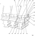
- FIG. 1 is a perspective view of a portion of a blade according to the invention lattice grate 1 a turbomachine with a first embodiment of blades according to the invention 2, 4 shown.
- the turbomachine is a gas turbine and in particular an aircraft engine.
- the blade grid 1 is preferably arranged on the turbine side and, for example, in a low-pressure turbine of the turbomachine.
- the blades 2, 4 are in the embodiment shown blades, but may, for example, in the Figures 3 and 4 explained, also be a guide vane.
- the blades 2, 4 are turbine blades.
- the blade lattice 1 has a hub-side side wall 6 and a housing-side side wall which radially delimit a hot gas passage through which a hot gas flows substantially in the axial direction of the turbomachine.
- a hot gas passage through which a hot gas flows substantially in the axial direction of the turbomachine For the sake of clarity, / are in FIG. 1 and in the following FIGS. 2 to 6 only the hub-side and inner side wall 6 are shown.
- the hub-side side wall 6 is of in FIG. 2 by way of example numbered hub-side or inner platforms 8, 10 of the blades 2, 4, which are arranged side by side in the circumferential direction and of which blades 12, 14 extend into the hot gas channel.
- the hub-side side wall 6 has a side wall leading edge 16, viewed in the flow direction of the hot gas, and a side wall trailing edge 18.
- the side wall leading edge 16 forms according to FIG. 1 a transition region between a hub-side side wall 6 radially inwardly positioned front and upstream side wall overhang 20 and the side wall 6.
- the side wall trailing edge 18 of the side wall 6 forms in the in FIG. 1 shown embodiment, a transition region to a rear or downstream side wall overhang 22 which is positioned radially inward to the front side wall overhang 20.
- the side wall leading edge 16, the side wall trailing edge 18, the front side wall overhang 20, and the rear side wall overhang 22 are formed from circumferentially adjacent individual platform leading edges 24, 26, platform trailing edges 28, 30, front platform overhangs 32, 34, and rear platform overhangs 36, 37, respectively ,
- the side wall leading edge 16 is rounded and provided with an edge contouring.
- the edge contouring is such that the sidewall leading edge 16 is circumferentially asymmetric.
- the edge contouring with respect to an ideal circumferentially symmetrical side leading edge is uniformly wave-like, wherein in the side edge region of the blades 2, 4 each on both platforms 8, 10 extending survey 38, 40 and between the elevations 38, 40 each have a recess 42 is arranged.
- two corresponding elevation portions 44, 46 are arranged, which taken alone from the side wall leading edge 16, the elevations 38, 40 form.
- the blades 12, 14 are in the illustrated embodiment, each with a Anströmkanten mineralen area 48 of its root fillet out in one of the elevation portions 46.
- the recess 42 is formed in each case between the raised portions 44, 46 and preferably centrally of the respective platform leading edge 24, 26 (s. FIG. 2 ) arranged.
- the recess 42 is offset radially inwardly from an ideal sidewall edge line or hot gas line, such that it contacts a radially outer leg 50 of the front sidewall overhang 20 with its deepest portion.
- the front side wall overhang 20, which is circumferentially symmetrical, thus passes at least in sections via its outer foot 50 directly into the recess 42.
- the elevations 38, 40 or elevation portions 44, 46 are spaced from the outer leg 50, wherein radially extending flanks 52, 54 between the outer foot 50 and the elevations 38, 40 and elevation portions 44, 46 are non-contoured.
- the edge contouring is elliptical or they are composed of several circle segments with different radii.
- the edge contouring merges into a circumferentially asymmetrical side wall 6 and a circumferentially asymmetric side wall contouring.
- the side wall contouring in each case has two hills which extend over the side edge region of the blades 2, 4 onto the respectively adjacent platform 8, 10.
- the mountains are arranged one behind the other and shown only as a mountain section 56, 58 due to the perspective.
- the front peak is spaced from a root-end suction-side area 60 by an unnumbered channel.
- the rear mountain extends from a non-contoured sidewall portion 62.
- the sidewall contour runs out in the direction of the sidewall trailing edge 18.
- the sidewall trailing edge 18 is non-contoured and thus circumferentially symmetric.
- the rear side wall overhang 22 is not contoured and thus circumferentially symmetrical.
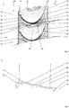
- FIG. 2 a hub-side peripheral portion of a blade lattice 1 is shown, which is formed from a plurality of the blades according to the invention 2, 4 as turbine blades according to a second embodiment.
- the airfoil 1 has a circumferentially symmetric front sidewall overhang 20, a circumferentially asymmetric sidewall leading edge 16, a circumferentially asymmetric sidewall 6, a circumferentially symmetric sidewall trailing edge 18, and a circumferentially symmetric trailing sidewall overhang 22.
- the circumferential asymetrical side wall leading edge 16 is rounded and has a circumferentially wavy edge contouring which is elliptical in the flow direction or viewed from the front side wall overhang 20 to the side wall 6 or consists of several circle segments with different radii.
- the edge contouring follows as in the embodiment FIG. 1 in a circumferentially asymmetric side wall contouring of the side wall 6 via.
- the side wall contouring of the side wall 6 has, according to the in FIG. 2 shown embodiment, two mountains 64, 66 near a suction side 67 each of an airfoil 12, 14 has.
- the mountains 64, 66 are spaced apart in the direction of flow and each extend beyond side edge portions of platforms 8, 10 of the adjacent blades 2, 4.
- a not provided with the mountains 64, 66 region of the side wall 6 and the platforms 8, 10 is provided with an extending beyond the side edge portions valley 68.
- the platforms each have two suction-side mountain portions 70, 72 and two quasi-pressure-side mountain portions 74, 76 which form the mountains 64, 66 with the respective corresponding mountain portions of the adjacent blades 2, 4.
- the mountains 64, 66 are each spaced by a channel from a suction-side region 60 of a root fillet. In addition, the root fillet is guided on the suction side to the respective adjacent platform 8, 10.
- FIG. 3 a section through an embodiment of the blade 2 according to the invention is shown, which is designed as a guide vane as a turbine guide vane of a turbomachine. Essentially different from the ones in the FIGS. 1 and 2 shown Embodiments, this blade 2 has no front side wall overhang and no rear side wall overhang.
- illustrated blade 2 has a hub-side circumferential asymmetric platform leading edge 24, a hub-side circumferential asymmetric platform 8, and a hub-side circumferentially symmetric platform trailing edge 28.
- the circumferentially asymmetric platform leading edge 24 is rounded and has a circumferentially wavy edge contouring that is elliptical in the flow direction or composed of multiple circle segments of different radii.
- the edge contouring is as in the embodiments of the FIGS. 1 and 2 into the platform 8 or a platform contouring over.
- the platform 8 with its contour of the platform, forms part of a circumferential asymetrical side wall contouring.
- the flat contour contouring is such that the sidewall contouring between each two airfoils 12 has a front peak 64 and a aft peak 66 which is lower compared to the front peak 64 and which is one with the front peak 64 the mountains 64, 66 reduced-height section 80 is connected.
- the platform contouring runs in the direction of the circumferentially symmetrical platform trailing edge 28, which in the exemplary embodiment shown here is preferably angular.
- a hub-side peripheral portion of a blade lattice 1 is shown, which is formed from a plurality of the blades 2, 4 according to the invention such as turbine vanes according to a fourth embodiment.
- the vane grille 1 has no front side wall overhang and no rear side wall overhang. However, it has a circumferentially asymmetric sidewall leading edge 16, a circumferentially asymmetric sidewall 6, and a circumferentially symmetrical sidewall trailing edge 18.
- the circumferentially asymmetric sidewall leading edge 16 is rounded and has a circumferentially wavy edge contour that is elliptical in the direction of flow or viewed from the front sidewall overhang to the sidewall, or composed of multiple circle segments of different radii.
- the edge contouring is as in the embodiments of the previous FIGS. 1 to 3 in the circumferentially asymmetric side wall 6 and in the side wall contouring about.
- the sidewall wall contouring has a peak 64 which extends between root fillets 82, 84 of the respective adjacent airfoils 12, 14 and merges into the root fillets 82, 84 at the level of an ideal hot gas line.
- the mountain 64 engages around a non-contoured side wall section 88, from which the suction-side root fillet 84 rises in a stepless manner.
- the sowandkonturising each between two blades 12, 14, a front valley 68 and a rear valley 86, which are separated by the mountain 64 from each other.
- the sidewall contouring proceeds at an approximate axial position of trailing edges 90 of the airfoils 12, 14 such that an unconstrained sidewall portion 62 is formed between the trailing edges 90 and the sidewall trailing edge 18.
- a non-inventive example of a blade 2 is shown formed as a blade such as a turbine blade of a turbomachine.
- the bucket 2 has a hub-side front platform overhang 32, a hub-side platform leading edge 24, a hub-side platform 8, a hub-side platform trailing edge 28, and a hub-side rear platform overhang 36.
- the platform 8 is not contoured, but formed circumferentially symmetrical.
- the rear platform overhang 36 continues an ideal hot gas duct line 78 of the platform 8, so unlike the latter Embodiments of the FIGS. 1 . 2 and 3 is not offset from the platform 8 radially inward, but forms the platform trailing edge 28.
- the front platform overhang 32, the rear platform overhang 36, and the platform trailing edge 28 are circumferentially symmetric.
- the platform leading edge 24 is rounded and has circumferentially asymmetric edge contouring that is elliptical in the direction of flow or from the front platform overhang 32 to the platform 6, or that is composed of a plurality of circular segments of different radii.
- the edge contouring can be wave-like in the circumferential direction as in the preceding embodiments.
- the edge contouring merges into or runs out in the circumferentially symmetric platform contouring.
- a blade lattice for a turbomachine having an inner sidewall and an outer sidewall for confining a hot gas passageway of the turbomachine, wherein at least one of the sidewalls has a rounded sidewall leading edge provided with circumferentially asymmetric edge contouring which is elliptical or is composed of a plurality of circular segments, a blade for such a blade grid and a turbomachine.
Landscapes
- Engineering & Computer Science (AREA)
- Physics & Mathematics (AREA)
- Fluid Mechanics (AREA)
- Mechanical Engineering (AREA)
- General Engineering & Computer Science (AREA)
- Turbine Rotor Nozzle Sealing (AREA)
Description
- Die Erfindung betrifft ein Schaufelgitter einer Strömungsmaschine nach dem Oberbegriff des Patentanspruchs 1 und eine Strömungsmaschine.
- Zur Minimierung von Sekundärströmungen sind Schaufelgitter in Strömungsmaschinen wie Gasturbinen und insbesondere Flugtriebwerken häufig mit einer nabenseitigen und/oder gehäuseseitigen Seitenwandkonturierung versehen, die einen von einem Heißgas durchströmten Heißgaskanal der Strömungsmaschine begrenzt. Aus Gründen der Spalthaltung eines Axialspaltes zu einem stromaufwärtigen Schaufelgitter ist eine Seitenwandvorderkante herkömmlicherweise umfangssymmetrisch ausgebildet nicht somit nicht-konturiert. Aus der
US 20100172749 A1 ist jedoch ein Schaufelgitter mit einer umfangsasymmetrischen Seitenwandvorderkante bekannt, die mit einer wellenförmigen Kantenkonturierung versehen ist, die sich pauschal aus einer Vielzahl von in Strömungsrichtung des Heißgases bzw. Axialrichtung der Strömungsmaschine abgerundeten oder angestellten Flächen zusammensetzt.WO2012157498A1 offenbart ein Schaufelgitter mit den Merkmalen des Oberbegriffs vom Anspruch 1. - Aufgabe der Erfindung ist es, ein Schaufelgitter einer Strömungsmaschine zu schaffen, das eine alternative Seitenvorderkantenkonturierung aufweist. Des Weiteren ist es Aufgabe der Erfindung eine Schaufel für ein derartiges Schaufelgitter und eine Strömungsmaschine mit einem derartigen Schaufelgitter zu schaffen.
- Diese Aufgabe wird gelöst durch ein Schaufelgitter mit den Merkmalen des Patentanspruchs 1 und durch eine Strömungsmaschine mit den Merkmalen des Patentanspruchs 11.
- Ein erfindungsgemäßes Schaufelgitter einer Strömungsmaschine hat eine innere Seitenwand und eine äußere Seitenwand zum Begrenzen eines von einem Heißgas durchströmten Heißgaskanals der Strömungsmaschine. Zumindest eine der Seitenwände hat eine abgerundete Seitenwandvorderkante hat, die mit einer umfangsasymmetrischen
- Kantenkonturierung versehen ist, die elliptisch ist oder aus einem oder mehreren Kreissegmenten zusammengesetzt ist.
- Die elliptische Ausbildung der Kantenkonturierung und/oder die Bildung der umfangsasymmetrischen Kantenkonturierung aus einer Vielzahl von Kreissegmenten in Strömungsrichtung des Heißgases bzw. in Axialrichtung der Strömungsmaschine betrachtet bewirkt eine Reduktion von Sekundärströmungen im Bereich der Seitenwandvorderkante gegenüber einem Schaufelgitter mit einer umfangssymmetrischen Seitenwandvorderkante. Des Weiteren wird beispielsweise durch die Kantenkonturierung an einer inneren bzw. nabenseitigen Seitenwandvorderkante eine Variationsreduzierung eines statischen Drucks in Umfangsrichtung im Heißgaskanal und im inneren Kühlkanal erzielt, was zu einer Reduzierung von lokalen Ein- und Ausströmintensitäten führt, wodurch Mischungsverluste zwischen dem Heißgas und Kühlluft reduziert werden. Zudem kann eine Leckageströmung mit ihren Strömungsstrukturen gezielt auf eine Sekundärströmung im Schaufelgitter abgestimmt werden.
- Bei einem bevorzugten Ausführungsbeispiel ist die Kantenkonturierung in Umfangsrichtung betrachtet wellenartig. Die Wellenkontur kann beispielsweise durch jeweils zwei Erhebungen und durch eine zwischen den Erhebungen angeordnete Vertiefung gebildet werden, wobei sich die Erhebungen über Seitenkanten der jeweils benachbarten Schaufeln erstrecken, so dass auf jeder Schaufel in deren Seitenkantenbereich zwei Erhebungsabschnitte gebildet sind, die jeweils mit einem korrespondierenden Erhebungsabschnitt der benachbarten Schaufel eine Erhebung bilden. Die Erhebungen und Vertiefungen beziehen sich jeweils auf eine ideale umfangssymmetrische Seitenwandvorderkante und bewirken eine weitere Reduzierung von Sekundärströmungen.
- Eine wurzelseitige Anströmung von Schaufelblättern des Schaufelgitters lässt sich verbessern, wenn Wurzelausrundungen der Schaufelblätter in die Kantenkonturierung hineingeführt sind.
- Die Sekundärströmungen lassen sich in Strömungsrichtung über die gesamte Seitenwand reduzieren, wenn ebenfalls die Seitenwand gemäß Anspruch 1 konturiert ist und insbesondere dann die Seitenwandkonturierung in die Seitenwandkonturierung integriert ist.
- Um einen vorderen Axialspalt trotz der Kantenkonturierung minimal zu halten, ist ein vorderer Seitenwandüberhang bevorzugterweise konturfrei und somit umfangssymmetrisch.
- Zur Reduzierung eines konstruktiven und fertigungstechnischen Aufwandes kann ein hinterer Seitenwandüberhang konturfrei und somit umfangssymmetrisch sein.
- Eine erfindungsgemäße Schaufel hat eine Plattform, deren Plattformvorderkante abgerundet ist und eine Kantenkonturierung aufweist, die elliptisch ist oder aus mehreren Kreissegmenten zusammengesetzt ist. Eine Vielzahl von derartigen Schaufeln ermöglicht die Bildung eines erfindungsgemäßen Schaufelgitters einer Strömungsmaschine, mittels dem seienwandseitige Sekundärströmungen im Heißgaskanal, statische Druckunterschiede und Mischungsverluste reduziert werden können. Zudem können Leckageströme gezielt durch das Schaufelgitter geführt werden.
- Eine erfindungsgemäße Strömungsmaschine weist zumindest ein erfindungsgemäßes Schaufelgitter auf. Eine derartige Strömungsmaschine wie eine Gasturbine und insbesondere ein Flugtriebwerk zeichnet sich durch einen höheren Wirkungsgrad aus, da seitenwandseitige Sekundärströmungen im Heißgaskanal, statische Druckunterschiede und Mischungsverluste reduziert werden können. Zudem können Leckageströme gezielt durch das Schaufelgitter geführt werden. Bevorzugterweise ist das zumindest eine Schaufelgitter turbinenseitig und beispielsweise in einer Niederdruckturbine der Strömungsmaschine angeordnet.
- Sonstige vorteilhafte Ausführungsbeispiele der Erfindung sind Gegenstand weiterer Unteransprüche.
- Im Folgenden werden bevorzugte Ausführungsbeispiele der Erfindung anhand schematischer Darstellungen näher erläutert. Es zeigen:
- Figur 1
- einen perspektivische Darstellung eines Teilbereichs eines erfindungsgemäßen Schaufelgitters mit einem ersten Ausführungsbeispiel einer erfindungsgemäßen Schaufel,
- Figur 2
- einen Umfangsabschnitt eines erfindungsgemäßen Schaufelgitter mit einem zweiten Ausführungsbeispiel der erfindungsgemäßen Schaufel,
- Figur 3
- eine Seitendarstellung eines dritten Ausführungsbeispiels der erfindungsgemäßen Schaufel,
- Figur 4
- einen Umfangsabschnitt eines erfindungsgemäßen Schaufelgitter mit einem vierten Ausführungsbeispiel der erfindungsgemäßen Schaufel,
- Figur 5
- eine perspektivische Darstellung eines nicht zur Erfindung gehörenden Beispiels einer Schaufel, und
- Figur 6
- eine Seitendarstellung der Schaufeln aus
Figur 5 . - In
Figur 1 ist eine perspektivische Darstellung eines Teilbereichs eines erfindungsgemäßen Schaufelgitters 1 einer Strömungsmaschine mit einem ersten Ausführungsbeispiel von erfindungsgemäßen Schaufeln 2, 4 gezeigt. Die Strömungsmaschine ist eine Gasturbine und insbesondere ein Flugtriebwerk. Das Schaufelgitter 1 ist bevorzugterweise turbinenseitig und beispielsweise in einer Niederdruckturbine der Strömungsmaschine angeordnet. Die Schaufeln 2, 4 sind in dem gezeigten Ausführungsbeispiel Laufschaufeln, können jedoch wie beispielsweise in denFiguren 3 und4 erläutert, auch Leitschaufels sein. Insbesondere sind die Schaufeln 2, 4 Turbinenschaufeln. - Das Schaufelgitter 1 hat eine nabenseitige Seitenwand 6 und eine gehäuseseitige Seitenwand, die einen von einem Heißgas im Wesentlichen in Axialrichtung der Strömungsmaschine durchströmten Heißgaskanal radial begrenzen. Aus Gründen der Übersichtlichkeit ist/sind in
Figur 1 und in den folgendenFiguren 2 bis 6 lediglich die nabenseitige bzw. innere Seitenwand 6 gezeigt. - Die nabenseitige Seitenwand 6 wird von in
Figur 2 beispielhaft bezifferten nabenseitigen bzw. inneren Plattformen 8, 10 der Schaufeln 2, 4 gebildet, die in Umfangsrichtung nebeneinander angeordnet sind und von denen sich Schaufelblätter 12, 14 in den Heißgaskanal erstrecken. Die nabenseitige Seitenwand 6 hat eine in Strömungsrichtung des Heißgases betrachtet Seitenwandvorderkante 16 und eine Seitenwandhinterkante 18. - Die Seitenwandvorderkante 16 bildet gemäß
Figur 1 einen Übergangsbereich zwischen einem zur nabenseitigen Seitenwand 6 radial innen positionierten vorderen bzw. stromaufwärtigen Seitenwandüberhang 20 und der Seitenwand 6. Die Seitenwandhinterkante 18 der Seitenwand 6 bildet in dem imFigur 1 gezeigten Ausführungsbeispiel einen Übergangsbereich zu einem hinteren bzw. stromabwärtigen Seitenwandüberhang 22, der radial innen zum vorderen Seitenwandüberhang 20 positioniert ist. - Entsprechend der Bildung der Seitenwand 6 werden wie in
Figur 2 anhand von Bezugsziffern verdeutlicht, die Seitenwandvorderkante 16, die Seitenwandhinterkante 18, der vordere Seitenwandüberhang 20 und der hintere Seitenwandüberhang 22 von in Umfangsrichtung nebeneinanderliegenden einzelnen Plattformvorderkanten 24, 26, Plattformhinterkanten 28, 30, vorderen Plattformüberhängen 32, 34 bzw. hinteren Plattformüberhängen 36, 37 gebildet. - Wie in
Figur 1 zu erkennen, ist die Seitenwandvorderkante 16 abgerundet ausgebildet und mit einer Kantenkonturierung versehen. Die Kantenkonturierung ist derart, dass die Seitenwandvorderkante 16 umfangsasymmetrisch ist. Bevorzugterweise ist die Kantenkonturierung bezogen auf eine ideale umfangsymmetrische Seitenvorderkante gleichmäßig wellenartig, wobei im Seitenkantenbereich der Schaufeln 2, 4 jeweils eine sich auf beide Plattformen 8, 10 erstreckende Erhebung 38, 40 und zwischen den Erhebungen 38, 40 jeweils eine Vertiefung 42 angeordnet ist. Somit sind im jeden Seitenkantenbereich der Schaufeln 2, 4 zwei korrespondierende Erhebungsabschnitte 44, 46 angeordnet, die für sich genommen isoliert von der Seitenwandvorderkante 16 die Erhebungen 38, 40 bilden. Die Schaufelblätter 12, 14 sind dabei in dem gezeigten Ausführungsbeispiel mit jeweils einem anströmkantenseitigen Bereich 48 ihrer Wurzelausrundung in einen der Erhebungsabschnitte 46 geführt. - Die Vertiefung 42 ist jeweils zwischen den Erhebungsabschnitten 44, 46 ausgebildet und bevorzugterweise mittig der jeweiligen Plattformvorderkante 24, 26 (s.
Figur 2 ) angeordnet. Die Vertiefung 42 ist derart gegenüber einer idealen Seitenwandkantenlinie bzw. Heißgaskanallinie radial nach innen versetzt, dass sie mit ihrem tiefsten Abschnitt einen radial äußeren Fuß 50 des vorderen Seitenwandüberhangs 20 berührt. Der vordere Seitenwandüberhang 20, der umfangssymmetrisch ist, geht somit zumindest abschnittsweise mit seinem äußeren Fuß 50 unmittelbar in die Vertiefung 42 über. Die Erhebungen 38, 40 bzw. Erhebungsabschnitte 44, 46 sind hingegen von dem äußeren Fuß 50 beabstandet, wobei sich radial erstreckende Freiflächen 52, 54 zwischen dem äußeren Fuß 50 und den Erhebungen 38, 40 bzw. Erhebungsabschnitte 44, 46 nicht-konturiert sind. - In Axialrichtung der Strömungsmaschine und somit vereinfacht in Strömungsrichtung bzw. von dem vorderen Seitenwandüberhang 20 zur Seitenwand 6 betrachtet, ist die Kantenkonturierung elliptisch oder sie setzen sich aus mehreren Kreissegmenten mit unterschiedlichen Radien zusammen.
- Die Kantenkonturierung geht in eine umfangsasymmetrische Seitenwand 6 bzw. eine umfangsasymmetrische Seitenwandkonturierung über. In dem in
Figur 1 gezeigten Ausführungsbeispiel hat die Seitenwandkonturierung jeweils zwei Berge, die sich über den Seitenkantenbereich der Schaufeln 2, 4 auf die jeweils benachbarte Plattform 8, 10 erstrecken. Die Berge sind hintereinander angeordnet und aufgrund der Perspektive lediglich jeweils als ein Bergabschnitt 56, 58 gezeigt. Der vordere Berg ist über einen nicht bezifferten Kanal von einem saugseitigen Bereich 60 der Wurzelausrundung beabstandet. Der hintere Berg erstreckt sich von einem nicht-konturierten Seitenwandabschnitt 62. - Die Seitenwandkonturierung läuft in Richtung der Seitenwandhinterkante 18 aus. Die Seitenwandhinterkante 18 ist nicht-konturiert und somit umfangssymmetrisch. Ebenso ist der hintere Seitenwandüberhang 22 nicht-konturiert und somit umfangssymmetrisch.
- In
Figur 2 ist ein nabenseitiger Umfangsabschnitt eines Schaufelgitters 1 gezeigt, das aus einer Vielzahl von den erfindungsgemäßen Schaufeln 2, 4 wie Turbinenlaufschaufeln gemäß einem zweiten Ausführungsbeispiel gebildet ist. Das Schaufelgitter 1 hat einen umfangssymmetrische vorderen Seitenwandüberhang 20, eine umfangsasymmetrische Seitenwandvorderkante 16 , eine umfangsasymmetrische Seitenwand 6, eine umfangssymmetrische Seitenwandhinterkante 18 und einen umfangssymmetrischen hinteren Seitenwandüberhang 22. - Die umfangsasymmetrische Seitenwandvorderkante 16 ist abgerundet und hat eine in Umfangsrichtung betrachtet wellenartige Kantenkonturierung, die in Strömungsrichtung bzw. von dem vorderen Seitenwandüberhang 20 zur Seitenwand 6 betrachtet elliptisch ist oder sich aus mehreren Kreissegmenten mit unterschiedlichen Radien zusammensetzt. Die Kantenkonturierung geht wie beim Ausführungsbeispiel nach
Figur 1 in eine umfangsasymmetrische Seitenwandkonturierung der Seitenwand 6 über. - Die Seitenwandkonturierung der Seitenwand 6 weist gemäß dem in
Figur 2 gezeigten Ausführungsbeispiel zwei Berge 64, 66 nahe einer Saugseite 67 jeweils eines Schaufelblattes 12, 14 aufweist. Die Berge 64, 66 sind in Strömungsrichtung voneinander beabstandet und erstrecken sich jeweils über Seitenkantenbereiche von Plattformen 8, 10 der benachbarten Schaufeln 2, 4 hinaus. Ein nicht mit den Bergen 64, 66 versehener Bereich der Seitenwand 6 bzw. der Plattformen 8, 10 ist mit einem sich über die Seitenkantenbereiche hinaus erstreckenden Tal 68 versehen. Somit weisen die Plattformen jeweils zwei saugseitige Bergabschnitte 70, 72 und zwei quasi druckseitige Bergabschnitte 74, 76 auf, die mit den jeweils korrespondierenden Bergabschnitten der benachbarten Schaufeln 2, 4 die Berge 64, 66 bilden. Die Berge 64, 66 sind jeweils über einen Kanal von einem saugseitigen Bereich 60 einer Wurzelausrundung beabstandet. Zudem ist die Wurzelausrundung saugseitig auf die jeweils benachbarte Plattform 8, 10 geführt. - In
Figur 3 ist ein Schnitt durch ein Ausführungsbeispiel der erfindungsgemäßen Schaufel 2 gezeigt, die als eine Leitschaufel wie eine Turbinenleitschaufel einer Strömungsmaschine ausgebildet ist. Im wesentlichen Unterschied zu den in denFiguren 1 und2 gezeigten Ausführungsbeispielen hat diese Schaufel 2 keinen vorderen Seitenwandüberhang und keinen hinteren Seitenwandüberhang. - Die in
Figur 3 gezeigte Schaufel 2 hat jedoch wie die vorhergehenden Ausführungsbeispiele eine nabenseitige umfangsasymmetrische Plattformvorderkante 24, eine nabenseitige umfangsasymmetrische Plattform 8 und eine nabenseitige umfangssymmetrische Plattformhinterkante 28. - Die umfangsasymmetrische Plattformvorderkante 24 ist abgerundet und hat eine in Umfangsrichtung betrachtet wellenartige Kantenkonturierung, die in Strömungsrichtung betrachtet elliptisch ist oder sich aus mehreren Kreissegmenten mit unterschiedlichen Radien zusammensetzt. Die Kantenkonturierung geht wie bei den Ausführungsbeispielen nach den
Figuren 1 und2 in die Plattform 8 bzw. eine Plattformkonturierung über. - Die Plattform 8 bildet mit ihrer Plattformkonturierung einen Teilbereich einer umfangsasymmetrischen Seitenwandkonturierung. Ausgehend von einer idealen Heißgaskanallinie 78 ist die Plattfomkonturierung derart, dass die Seitenwandkonturierung zwischen jeweils zwei Schaufelblättern 12 einen vorderen Berg 64 und einen hinteren Berg 66 hat, der im Vergleich zum vorderen Berg 64 niedriger ausgebildet ist und der mit dem vorderen Berg 64 über einen zu den Bergen 64, 66 höhenreduzierten Abschnitt 80 verbunden ist. Die Plattformkonturierung läuft in Richtung der umfangssymmetrischen Plattformhinterkante 28 aus, die in dem hier gezeigten Ausführungsbeispiel bevorzugterweise eckig ist.
- In
Figur 4 ist ein nabenseitiger Umfangsabschnitt eines Schaufelgitters 1 gezeigt, das aus einer Vielzahl von den erfindungsgemäßen Schaufeln 2, 4 wie Turbinenleitaufschaufeln gemäß einem vierten Ausführungsbeispiel gebildet ist. Entsprechend der bevorzugten Ausbildung der Schaufeln 2, 4 als Turbinenleitschaufel hat das Schaufelgitter 1 keinen vorderen Seitenwandüberhang und keinen hinteren Seitenwandüberhang. Es hat jedoch eine umfangsasymmetrische Seitenwandvorderkante 16, eine umfangsasymmetrische Seitenwand 6 und eine umfangssymmetrische Seitenwandhinterkante 18. - Die umfangsasymmetrische Seitenwandvorderkante 16 ist abgerundet und hat eine in Umfangsrichtung betrachtet wellenartige Kantenkonturierung, die in Strömungsrichtung bzw. von dem vordern Seitenwandüberhang zur Seitenwand betrachtet elliptisch ist oder sich aus mehreren Kreissegmenten mit unterschiedlichen Radien zusammensetzt. Die Kantenkonturierung geht wie beim Ausführungsbeispielen nach den vorhergehenden
Figuren 1 bis 3 in die umfangsasymmetrische Seitenwand 6 bzw. in deren Seitenwandkonturierung über. - Die Seitenwandwandkonturierung weist einen Berg 64 auf, der sich zwischen Wurzelausrundungen 82, 84 der jeweils benachbarten Schaufelblätter 12, 14 erstreckt und auf Höhe einer idealen Heißgaskanallinie in die Wurzelausrundungen 82, 84 übergeht. Im Bereich der saugseitigen Wurzelausrundung 84 umgreift der Berg 64 einen nicht-konturierten Seitenwandabschnitt 88, von dem sich die saugseitigen Wurzelausrundung 84 stufenlos erhebt. Zudem hat die Seitenwandkonturierung jeweils zwischen zwei Schaufelblättern 12, 14 ein vorderes Tal 68 und ein hinteres Tal 86, die durch den Berg 64 voneinander getrennt sind.
- Wie zudem in
Figur 4 zu erkennen, läuft die Seitenwandkonturierung an einer ungefähren axialen Position von Abströmkanten 90 der Schaufelblätter 12, 14 aus, sodass zwischen den Abströmkanten 90 und der Seitenwandhinterkante 18 ein nicht-konturierter Seitenwandabschnitt 62 gebildet ist. - In den
Figuren 5 und 6 ist ein nicht zur Erfindung gehörendes Beispiel einer Schaufel 2 gezeigt, die als eine Laufschaufel wie eine Turbinenlaufschaufel einer Strömungsmaschine ausgebildet ist. Die Schaufel 2 hat einen nabenseitigen vorderen Plattformüberhang 32, eine nabenseitigen Plattformvorderkante 24, eine nabenseitigen Plattform 8, eine nabenseitigen Plattformhinterkante 28 und einen nabenseitigen hinteren Plattformüberhang 36. - Im wesentlichen Unterschied zu den Ausführungsbeispielen nach den
Figuren 1 bis 4 ist die Plattform 8 nicht-konturiert, sondern umfangssymmetrisch ausgebildet. - Im weiteren wesentlichen Unterschied führt der hintere Plattformüberhang 36 eine ideale Heißgaskanallinie 78 der Plattform 8 fort, so dass dieser im Unterschied zu den Ausführungsbeispielen nach den
Figuren 1 ,2 und 3 nicht gegenüber der Plattform 8 radial nach innen versetzt ist, sondern die Plattformhinterkante 28 bildet. Entsprechend den Ausführungsbeispielen nach denFiguren 1 ,2 und 3 sind der vordere Plattformüberhang 32, der hintere Plattformüberhang 36 und die Plattformhinterkante 28 umfangssymmetrisch. - Die Plattformvorderkante 24 ist abgerundet und hat eine in Umfangsrichtung betrachtet umfangsasymmetrische Kantenkonturierung, die in Strömungsrichtung bzw. von dem vorderen Plattformüberhang 32 zur Plattform 6 betrachtet elliptisch ist oder sich aus mehreren Kreissegmenten mit unterschiedlichen Radien zusammensetzt. Dabei kann die Kantenkonturierung wie bei den vorhergehenden Ausführungsbeispielen in Umfangsrichtung wellenartig sein. Die Kantenkonturierung geht in die umfangssymmetrische Plattformkonturierung über bzw. läuft in dieser aus.
- Es sei erwähnt, dass, auch wenn sich in den
Figuren 1 bis 6 lediglich auf die nabenseitige bzw. innere Seitenwand 6 / Plattformen 8, 10 bezogen wird, selbstverständlich sämtliche Überlegungen bzw. Konturierungen bzw. Nicht-Konturierungen auch bei einer gehäuseseitigen bzw. äußeren Seitenwand / Plattform Anwendung finden können. Insbesondere können sowohl die nabenseitige Seitenwand 6 als auch die gehäuseseitige Seitenwand sowie die hierfür notwendigen Schaufelplattformen 8, 10 zum Begrenzen eines Heißgaskanals einer Strömungsmaschine entsprechend konturiert sein. - Offenbart ist ein Schaufelgitter für eine Strömungsmaschine, die eine innere Seitenwand und eine äußere Seitenwand zum Begrenzen eines von einem Heißgas durchströmten Heißgaskanals der Strömungsmaschine hat, wobei zumindest einer der Seitenwände eine abgerundete Seitenwandvorderkante hat, die mit einer umfangsasymmetrischen Kantenkonturierung versehen ist, die elliptisch ist oder aus mehreren Kreissegmenten zusammengesetzt ist, eine Schaufel für ein derartiges Schaufelgitter und eine Strömungsmaschine.
-
- 1
- Schaufelgitter
- 2
- Schaufel
- 4
- Schaufel
- 6
- innere / nabenseitige Seitenwand
- 8
- Plattform / Schaufelplattform
- 10
- Plattform / Schaufelplattform
- 12
- Schaufelblatt
- 14
- Schaufelblatt
- 16
- Seitenwandvorderkante
- 18
- Seitenwandhinterkante
- 20
- vorderer Seitenwandüberhang
- 22
- hinterer Seitenwandüberhang
- 24
- Plattformvorderkante
- 26
- Plattformvorderkante
- 28
- Plattformhinterkante
- 30
- Plattformhinterkante
- 32
- vorderer Plattformüberhang
- 34
- vorderer Plattformüberhang
- 36
- hinterer Plattformüberhang
- 37
- hinterer Plattformüberhang
- 38
- Erhebung
- 40
- Erhebung
- 42
- Vertiefung
- 44
- Erhebungsabschnitt
- 46
- Erhebungsabschnitt
- 48
- anströmkantenseitiger Bereich einer Wurzelausrundung
- 50
- äußerer Fuß
- 52
- Freifläche
- 54
- Freifläche
- 56
- Bergabschnitt
- 58
- Bergabschnitt
- 60
- saugseitiger Bereich einer Wurzelausrundung
- 62
- nicht-konturierter Seitenwandabschnitt
- 64
- Berg
- 66
- Berg
- 67
- Saugseite
- 68
- Tal
- 70
- Bergabschnitt
- 72
- Bergabschnitt
- 74
- Bergabschnitt
- 76
- Bergabschnitt
- 78
- ideale Heißgaskanallinie / ideale Plattformlinie
- 80
- höhenreduzierter Abschnitt
- 82
- Wurzelausrundung
- 84
- Wurzelausrundung
- 86
- Tal
- 88
- nicht-konturierter Seitenwandabschnitt
- 90
- Abströmkante
Claims (11)
- Schaufelgitter (1) einer Strömungsmaschine, das eine innere Seitenwand (6) und eine äußere Seitenwand zum Begrenzen eines von einem Heißgas durchströmten Heißgaskanals der Strömungsmaschine hat, wobei zumindest eine der Seitenwände (6) eine abgerundete Seitenwandvorderkante (16) hat, die mit einer umfangsasymmetrischen Kantenkonturierung versehen ist, wobei die Kantenkonturierung elliptisch ist oder aus einem oder mehreren Kreissegmenten zusammengesetzt ist, wobei das Schaufelgitter (1) mindestens zwei Schaufeln (2, 4) mit je einem Schaufelblatt (12, 14) umfasst, wobei um jedes Schaufelblatt (12, 14) eine Wurzelausrundung (60, 82, 84) angeordnet ist, dadurch gekennzeichnet, dass mindestens einer der Seitenwände (6) derart konturiert ist, dass sich ein Berg (64) oder zwei Berge (56, 58; 64, 66) zwischen den Wurzelausrundungen (82, 84) der jeweils benachbarten Schaufelblätter (12. 14) erstrecken.
- Schaufelgitter nach Anspruch 1, wobei die Kantenkonturierung in Umfangsrichtung wellenartig ist.
- Schaufelgitter nach Anspruch 1 oder 2, wobei Wurzelausrundungen von Schaufelblättern (12, 14) in die Kantenkonturierung hineingeführt sind.
- Schaufelgitter nach einem der vorhergehenden Ansprüche, wobei bei zwei Bergen (56, 58, 64, 66) die jeweils beiden Berge (56, 58; 64, 66) in Strömungsrichtung voneinander beabstandet sind.
- Schaufelgitter nach einem der vorhergehenden Ansprüche, wobei bei zwei Bergen (64, 66) der Berg (64) auf der Höhe einer idealen Heißgaskanallinie in die Wurzelausrundung (82, 84) übergeht.
- Schaufelgitter nach einem der vorhergehenden Ansprüche, wobei bei zwei Bergen (64, 66) die beiden Berge (64, 66) in der Nähe einer Saugseite (67) eines Schaufelblattes (12. 14) angeordnet sind.
- Schaufelgitter nach einem der vorhergehenden Ansprüche, wobei bei zwei Bergen (64, 66) der hintere Berg (66) niedriger ist als der vordere Berg (64) und über einen höhenreduzierten Abschnitt (80) verbunden ist, der über einer idealen Heißkanallinie (78) verläuft.
- Schaufelgitter nach einem der Ansprüche 1 bis 6, wobei bei zwei Bergen (56, 58; 64, 66) ein vorderer Seitenwandüberhang (20) konturfrei ist.
- Schaufelgitter nach einem der Ansprüche 1 bis 6 oder 8, wobei bei zwei Bergen (56, 58; 64, 66) ein hinterer Seitenwandüberhang (22) konturfrei ist.
- Schaufelgitter nach Anspruch 1, 2 oder 3, wobei bei einem Berg (64) eine innere Seitenwandhinterkante (18) konturfrei ist.
- Strömungsmaschine mit zumindest einem Schaufelgitter nach einem der Ansprüche 1 bis 10.
Priority Applications (3)
| Application Number | Priority Date | Filing Date | Title |
|---|---|---|---|
| EP13169058.8A EP2806103B1 (de) | 2013-05-24 | 2013-05-24 | Schaufelgitter und Strömungsmaschine |
| ES13169058T ES2742377T3 (es) | 2013-05-24 | 2013-05-24 | Rejilla de álabes y turbomáquina |
| US14/286,592 US20140348661A1 (en) | 2013-05-24 | 2014-05-23 | Blade row, blade and turbomachine |
Applications Claiming Priority (1)
| Application Number | Priority Date | Filing Date | Title |
|---|---|---|---|
| EP13169058.8A EP2806103B1 (de) | 2013-05-24 | 2013-05-24 | Schaufelgitter und Strömungsmaschine |
Publications (2)
| Publication Number | Publication Date |
|---|---|
| EP2806103A1 EP2806103A1 (de) | 2014-11-26 |
| EP2806103B1 true EP2806103B1 (de) | 2019-07-17 |
Family
ID=48534184
Family Applications (1)
| Application Number | Title | Priority Date | Filing Date |
|---|---|---|---|
| EP13169058.8A Active EP2806103B1 (de) | 2013-05-24 | 2013-05-24 | Schaufelgitter und Strömungsmaschine |
Country Status (3)
| Country | Link |
|---|---|
| US (1) | US20140348661A1 (de) |
| EP (1) | EP2806103B1 (de) |
| ES (1) | ES2742377T3 (de) |
Cited By (2)
| Publication number | Priority date | Publication date | Assignee | Title |
|---|---|---|---|---|
| US12196110B2 (en) | 2022-03-04 | 2025-01-14 | MTU Aero Engines AG | Blisk for a gas turbine |
| US12698713B2 (en) | 2022-05-31 | 2026-08-04 | MTU Aero Engines AG | Annulus contouring |
Families Citing this family (6)
| Publication number | Priority date | Publication date | Assignee | Title |
|---|---|---|---|---|
| EP2650475B1 (de) * | 2012-04-13 | 2015-09-16 | MTU Aero Engines AG | Schaufel für eine Strömungsmaschine, Schaufelanordnung sowie Strömungsmaschine |
| US10030523B2 (en) * | 2015-02-13 | 2018-07-24 | United Technologies Corporation | Article having cooling passage with undulating profile |
| EP3064706A1 (de) * | 2015-03-04 | 2016-09-07 | Siemens Aktiengesellschaft | Leitschaufelreihe für eine axial durchströmte Strömungsmaschine |
| DE102015224376A1 (de) * | 2015-12-04 | 2017-06-08 | MTU Aero Engines AG | Schaufelkanal, Schaufelgitter und Strömungsmaschine |
| DE102016211315A1 (de) | 2016-06-23 | 2017-12-28 | MTU Aero Engines AG | Lauf- oder Leitschaufel mit erhabenen Bereichen |
| ES2985811T3 (es) | 2017-05-10 | 2024-11-07 | MTU Aero Engines AG | Rejilla de álabe |
Family Cites Families (17)
| Publication number | Priority date | Publication date | Assignee | Title |
|---|---|---|---|---|
| WO1998044240A1 (de) * | 1997-04-01 | 1998-10-08 | Siemens Aktiengesellschaft | Oberflächenstruktur für die wand eines strömungskanals oder einer turbinenschaufel |
| US6511294B1 (en) * | 1999-09-23 | 2003-01-28 | General Electric Company | Reduced-stress compressor blisk flowpath |
| US6669445B2 (en) * | 2002-03-07 | 2003-12-30 | United Technologies Corporation | Endwall shape for use in turbomachinery |
| WO2006033407A1 (ja) * | 2004-09-24 | 2006-03-30 | Ishikawajima-Harima Heavy Industries Co., Ltd. | 軸流機械の壁形状及びガスタービンエンジン |
| US7249933B2 (en) * | 2005-01-10 | 2007-07-31 | General Electric Company | Funnel fillet turbine stage |
| JP5283855B2 (ja) | 2007-03-29 | 2013-09-04 | 株式会社Ihi | ターボ機械の壁、及びターボ機械 |
| DE102007027427A1 (de) * | 2007-06-14 | 2008-12-18 | Rolls-Royce Deutschland Ltd & Co Kg | Schaufeldeckband mit Überstand |
| DE102008031789A1 (de) * | 2008-07-04 | 2010-01-07 | Deutsches Zentrum für Luft- und Raumfahrt e.V. | Verfahren und Vorrichtung zur Beeinflussung von Sekundärströmungen bei einer Turbomaschine |
| US8647067B2 (en) * | 2008-12-09 | 2014-02-11 | General Electric Company | Banked platform turbine blade |
| EP2261462A1 (de) * | 2009-06-02 | 2010-12-15 | Alstom Technology Ltd | Turbinenstufenendwand |
| FR2950942B1 (fr) * | 2009-10-02 | 2013-08-02 | Snecma | Rotor d'un compresseur de turbomachine a paroi d'extremite interne optimisee |
| US8951014B2 (en) * | 2011-03-15 | 2015-02-10 | United Technologies Corporation | Turbine blade with mate face cooling air flow |
| JP5842382B2 (ja) * | 2011-05-13 | 2016-01-13 | 株式会社Ihi | ガスタービンエンジン |
| US8721291B2 (en) * | 2011-07-12 | 2014-05-13 | Siemens Energy, Inc. | Flow directing member for gas turbine engine |
| US20130089430A1 (en) * | 2011-10-11 | 2013-04-11 | General Electric Company | Turbomachine component having a flow contour feature |
| US8807930B2 (en) * | 2011-11-01 | 2014-08-19 | United Technologies Corporation | Non axis-symmetric stator vane endwall contour |
| US9103213B2 (en) * | 2012-02-29 | 2015-08-11 | General Electric Company | Scalloped surface turbine stage with purge trough |
-
2013
- 2013-05-24 EP EP13169058.8A patent/EP2806103B1/de active Active
- 2013-05-24 ES ES13169058T patent/ES2742377T3/es active Active
-
2014
- 2014-05-23 US US14/286,592 patent/US20140348661A1/en not_active Abandoned
Non-Patent Citations (1)
| Title |
|---|
| None * |
Cited By (2)
| Publication number | Priority date | Publication date | Assignee | Title |
|---|---|---|---|---|
| US12196110B2 (en) | 2022-03-04 | 2025-01-14 | MTU Aero Engines AG | Blisk for a gas turbine |
| US12698713B2 (en) | 2022-05-31 | 2026-08-04 | MTU Aero Engines AG | Annulus contouring |
Also Published As
| Publication number | Publication date |
|---|---|
| US20140348661A1 (en) | 2014-11-27 |
| ES2742377T3 (es) | 2020-02-14 |
| EP2806103A1 (de) | 2014-11-26 |
Similar Documents
| Publication | Publication Date | Title |
|---|---|---|
| EP2746533B1 (de) | Schaufelgitter und Strömungsmaschine | |
| EP2787171B1 (de) | Schaufelgitter mit Seitenwandkonturierung und Strömungsmaschine | |
| EP2806103A1 (de) | Schaufelgitter, Schaufel und Strömungsmaschine | |
| EP2806102B1 (de) | Schaufelgitter einer Strömungsmaschine und zugehörige Strömungsmaschine | |
| EP2696029B1 (de) | Schaufelgitter mit Seitenwandkonturierung und Strömungsmaschine | |
| DE60206129T2 (de) | Turbinenschaufel mit einer Abwärtsstufe in der Plattform, sowie entsprechende Turbine | |
| DE102015111750A1 (de) | Gekühltes Turbinenlaufrad für ein Flugtriebwerk | |
| DE102007020025A1 (de) | Form eines Gaskanals in einer Axialströmungs-Gasturbinenmaschine | |
| DE102015224283A1 (de) | Leitschaufelcluster für eine Strömungsmaschine | |
| DE102015224376A1 (de) | Schaufelkanal, Schaufelgitter und Strömungsmaschine | |
| EP3388626B1 (de) | Konturierung einer schaufelgitterplattform | |
| EP3401504B1 (de) | Schaufelgitter | |
| EP2597257B1 (de) | Beschaufelung | |
| EP2787178B1 (de) | Leitschaufelanordnung | |
| WO2005116404A1 (de) | Schaufelblatt mit übergangszone | |
| EP2730745B1 (de) | Schaufelanordnung für eine Turbomaschine | |
| EP3428391B1 (de) | Turbomaschinen-schaufelgitter | |
| EP3375977A1 (de) | Konturierung einer schaufelgitterplattform | |
| EP2631429B1 (de) | Beschaufelung | |
| EP2650475B1 (de) | Schaufel für eine Strömungsmaschine, Schaufelanordnung sowie Strömungsmaschine | |
| EP3369892B1 (de) | Konturierung einer schaufelgitterplattform | |
| EP2860356A1 (de) | Strömungsmaschine | |
| DE102012207735B4 (de) | Schaufelgitter einer Strömungsmaschine | |
| DE102021109844A1 (de) | Gasturbinen-Schaufelanordnung | |
| EP4286647B1 (de) | Ringraumkonturierung |
Legal Events
| Date | Code | Title | Description |
|---|---|---|---|
| PUAI | Public reference made under article 153(3) epc to a published international application that has entered the european phase |
Free format text: ORIGINAL CODE: 0009012 |
|
| 17P | Request for examination filed |
Effective date: 20130524 |
|
| AK | Designated contracting states |
Kind code of ref document: A1 Designated state(s): AL AT BE BG CH CY CZ DE DK EE ES FI FR GB GR HR HU IE IS IT LI LT LU LV MC MK MT NL NO PL PT RO RS SE SI SK SM TR |
|
| AX | Request for extension of the european patent |
Extension state: BA ME |
|
| R17P | Request for examination filed (corrected) |
Effective date: 20150413 |
|
| RBV | Designated contracting states (corrected) |
Designated state(s): AL AT BE BG CH CY CZ DE DK EE ES FI FR GB GR HR HU IE IS IT LI LT LU LV MC MK MT NL NO PL PT RO RS SE SI SK SM TR |
|
| RAP1 | Party data changed (applicant data changed or rights of an application transferred) |
Owner name: MTU AERO ENGINES AG |
|
| STAA | Information on the status of an ep patent application or granted ep patent |
Free format text: STATUS: EXAMINATION IS IN PROGRESS |
|
| 17Q | First examination report despatched |
Effective date: 20180625 |
|
| GRAP | Despatch of communication of intention to grant a patent |
Free format text: ORIGINAL CODE: EPIDOSNIGR1 |
|
| STAA | Information on the status of an ep patent application or granted ep patent |
Free format text: STATUS: GRANT OF PATENT IS INTENDED |
|
| INTG | Intention to grant announced |
Effective date: 20190319 |
|
| RIN1 | Information on inventor provided before grant (corrected) |
Inventor name: MAHLE, INGA Inventor name: PERNLEITNER, MARTIN Inventor name: ENGEL, KARL |
|
| GRAS | Grant fee paid |
Free format text: ORIGINAL CODE: EPIDOSNIGR3 |
|
| GRAA | (expected) grant |
Free format text: ORIGINAL CODE: 0009210 |
|
| STAA | Information on the status of an ep patent application or granted ep patent |
Free format text: STATUS: THE PATENT HAS BEEN GRANTED |
|
| AK | Designated contracting states |
Kind code of ref document: B1 Designated state(s): AL AT BE BG CH CY CZ DE DK EE ES FI FR GB GR HR HU IE IS IT LI LT LU LV MC MK MT NL NO PL PT RO RS SE SI SK SM TR |
|
| REG | Reference to a national code |
Ref country code: GB Ref legal event code: FG4D Free format text: NOT ENGLISH |
|
| REG | Reference to a national code |
Ref country code: CH Ref legal event code: EP |
|
| REG | Reference to a national code |
Ref country code: IE Ref legal event code: FG4D Free format text: LANGUAGE OF EP DOCUMENT: GERMAN |
|
| REG | Reference to a national code |
Ref country code: DE Ref legal event code: R096 Ref document number: 502013013171 Country of ref document: DE |
|
| REG | Reference to a national code |
Ref country code: AT Ref legal event code: REF Ref document number: 1155999 Country of ref document: AT Kind code of ref document: T Effective date: 20190815 |
|
| REG | Reference to a national code |
Ref country code: NL Ref legal event code: MP Effective date: 20190717 |
|
| REG | Reference to a national code |
Ref country code: LT Ref legal event code: MG4D |
|
| PG25 | Lapsed in a contracting state [announced via postgrant information from national office to epo] |
Ref country code: NO Free format text: LAPSE BECAUSE OF FAILURE TO SUBMIT A TRANSLATION OF THE DESCRIPTION OR TO PAY THE FEE WITHIN THE PRESCRIBED TIME-LIMIT Effective date: 20191017 Ref country code: LT Free format text: LAPSE BECAUSE OF FAILURE TO SUBMIT A TRANSLATION OF THE DESCRIPTION OR TO PAY THE FEE WITHIN THE PRESCRIBED TIME-LIMIT Effective date: 20190717 Ref country code: PT Free format text: LAPSE BECAUSE OF FAILURE TO SUBMIT A TRANSLATION OF THE DESCRIPTION OR TO PAY THE FEE WITHIN THE PRESCRIBED TIME-LIMIT Effective date: 20191118 Ref country code: BG Free format text: LAPSE BECAUSE OF FAILURE TO SUBMIT A TRANSLATION OF THE DESCRIPTION OR TO PAY THE FEE WITHIN THE PRESCRIBED TIME-LIMIT Effective date: 20191017 Ref country code: NL Free format text: LAPSE BECAUSE OF FAILURE TO SUBMIT A TRANSLATION OF THE DESCRIPTION OR TO PAY THE FEE WITHIN THE PRESCRIBED TIME-LIMIT Effective date: 20190717 Ref country code: FI Free format text: LAPSE BECAUSE OF FAILURE TO SUBMIT A TRANSLATION OF THE DESCRIPTION OR TO PAY THE FEE WITHIN THE PRESCRIBED TIME-LIMIT Effective date: 20190717 Ref country code: HR Free format text: LAPSE BECAUSE OF FAILURE TO SUBMIT A TRANSLATION OF THE DESCRIPTION OR TO PAY THE FEE WITHIN THE PRESCRIBED TIME-LIMIT Effective date: 20190717 Ref country code: SE Free format text: LAPSE BECAUSE OF FAILURE TO SUBMIT A TRANSLATION OF THE DESCRIPTION OR TO PAY THE FEE WITHIN THE PRESCRIBED TIME-LIMIT Effective date: 20190717 |
|
| REG | Reference to a national code |
Ref country code: ES Ref legal event code: FG2A Ref document number: 2742377 Country of ref document: ES Kind code of ref document: T3 Effective date: 20200214 |
|
| PG25 | Lapsed in a contracting state [announced via postgrant information from national office to epo] |
Ref country code: AL Free format text: LAPSE BECAUSE OF FAILURE TO SUBMIT A TRANSLATION OF THE DESCRIPTION OR TO PAY THE FEE WITHIN THE PRESCRIBED TIME-LIMIT Effective date: 20190717 Ref country code: GR Free format text: LAPSE BECAUSE OF FAILURE TO SUBMIT A TRANSLATION OF THE DESCRIPTION OR TO PAY THE FEE WITHIN THE PRESCRIBED TIME-LIMIT Effective date: 20191018 Ref country code: RS Free format text: LAPSE BECAUSE OF FAILURE TO SUBMIT A TRANSLATION OF THE DESCRIPTION OR TO PAY THE FEE WITHIN THE PRESCRIBED TIME-LIMIT Effective date: 20190717 Ref country code: IS Free format text: LAPSE BECAUSE OF FAILURE TO SUBMIT A TRANSLATION OF THE DESCRIPTION OR TO PAY THE FEE WITHIN THE PRESCRIBED TIME-LIMIT Effective date: 20191117 Ref country code: LV Free format text: LAPSE BECAUSE OF FAILURE TO SUBMIT A TRANSLATION OF THE DESCRIPTION OR TO PAY THE FEE WITHIN THE PRESCRIBED TIME-LIMIT Effective date: 20190717 |
|
| PG25 | Lapsed in a contracting state [announced via postgrant information from national office to epo] |
Ref country code: TR Free format text: LAPSE BECAUSE OF FAILURE TO SUBMIT A TRANSLATION OF THE DESCRIPTION OR TO PAY THE FEE WITHIN THE PRESCRIBED TIME-LIMIT Effective date: 20190717 |
|
| PG25 | Lapsed in a contracting state [announced via postgrant information from national office to epo] |
Ref country code: RO Free format text: LAPSE BECAUSE OF FAILURE TO SUBMIT A TRANSLATION OF THE DESCRIPTION OR TO PAY THE FEE WITHIN THE PRESCRIBED TIME-LIMIT Effective date: 20190717 Ref country code: IT Free format text: LAPSE BECAUSE OF FAILURE TO SUBMIT A TRANSLATION OF THE DESCRIPTION OR TO PAY THE FEE WITHIN THE PRESCRIBED TIME-LIMIT Effective date: 20190717 Ref country code: DK Free format text: LAPSE BECAUSE OF FAILURE TO SUBMIT A TRANSLATION OF THE DESCRIPTION OR TO PAY THE FEE WITHIN THE PRESCRIBED TIME-LIMIT Effective date: 20190717 Ref country code: PL Free format text: LAPSE BECAUSE OF FAILURE TO SUBMIT A TRANSLATION OF THE DESCRIPTION OR TO PAY THE FEE WITHIN THE PRESCRIBED TIME-LIMIT Effective date: 20190717 Ref country code: EE Free format text: LAPSE BECAUSE OF FAILURE TO SUBMIT A TRANSLATION OF THE DESCRIPTION OR TO PAY THE FEE WITHIN THE PRESCRIBED TIME-LIMIT Effective date: 20190717 |
|
| PG25 | Lapsed in a contracting state [announced via postgrant information from national office to epo] |
Ref country code: SK Free format text: LAPSE BECAUSE OF FAILURE TO SUBMIT A TRANSLATION OF THE DESCRIPTION OR TO PAY THE FEE WITHIN THE PRESCRIBED TIME-LIMIT Effective date: 20190717 Ref country code: CZ Free format text: LAPSE BECAUSE OF FAILURE TO SUBMIT A TRANSLATION OF THE DESCRIPTION OR TO PAY THE FEE WITHIN THE PRESCRIBED TIME-LIMIT Effective date: 20190717 Ref country code: SM Free format text: LAPSE BECAUSE OF FAILURE TO SUBMIT A TRANSLATION OF THE DESCRIPTION OR TO PAY THE FEE WITHIN THE PRESCRIBED TIME-LIMIT Effective date: 20190717 Ref country code: IS Free format text: LAPSE BECAUSE OF FAILURE TO SUBMIT A TRANSLATION OF THE DESCRIPTION OR TO PAY THE FEE WITHIN THE PRESCRIBED TIME-LIMIT Effective date: 20200224 |
|
| REG | Reference to a national code |
Ref country code: DE Ref legal event code: R097 Ref document number: 502013013171 Country of ref document: DE |
|
| PLBE | No opposition filed within time limit |
Free format text: ORIGINAL CODE: 0009261 |
|
| STAA | Information on the status of an ep patent application or granted ep patent |
Free format text: STATUS: NO OPPOSITION FILED WITHIN TIME LIMIT |
|
| PG2D | Information on lapse in contracting state deleted |
Ref country code: IS |
|
| 26N | No opposition filed |
Effective date: 20200603 |
|
| PG25 | Lapsed in a contracting state [announced via postgrant information from national office to epo] |
Ref country code: SI Free format text: LAPSE BECAUSE OF FAILURE TO SUBMIT A TRANSLATION OF THE DESCRIPTION OR TO PAY THE FEE WITHIN THE PRESCRIBED TIME-LIMIT Effective date: 20190717 |
|
| PG25 | Lapsed in a contracting state [announced via postgrant information from national office to epo] |
Ref country code: CH Free format text: LAPSE BECAUSE OF NON-PAYMENT OF DUE FEES Effective date: 20200531 Ref country code: LI Free format text: LAPSE BECAUSE OF NON-PAYMENT OF DUE FEES Effective date: 20200531 Ref country code: MC Free format text: LAPSE BECAUSE OF FAILURE TO SUBMIT A TRANSLATION OF THE DESCRIPTION OR TO PAY THE FEE WITHIN THE PRESCRIBED TIME-LIMIT Effective date: 20190717 |
|
| REG | Reference to a national code |
Ref country code: BE Ref legal event code: MM Effective date: 20200531 |
|
| PG25 | Lapsed in a contracting state [announced via postgrant information from national office to epo] |
Ref country code: LU Free format text: LAPSE BECAUSE OF NON-PAYMENT OF DUE FEES Effective date: 20200524 |
|
| PG25 | Lapsed in a contracting state [announced via postgrant information from national office to epo] |
Ref country code: IE Free format text: LAPSE BECAUSE OF NON-PAYMENT OF DUE FEES Effective date: 20200524 |
|
| PG25 | Lapsed in a contracting state [announced via postgrant information from national office to epo] |
Ref country code: BE Free format text: LAPSE BECAUSE OF NON-PAYMENT OF DUE FEES Effective date: 20200531 |
|
| REG | Reference to a national code |
Ref country code: AT Ref legal event code: MM01 Ref document number: 1155999 Country of ref document: AT Kind code of ref document: T Effective date: 20200524 |
|
| PG25 | Lapsed in a contracting state [announced via postgrant information from national office to epo] |
Ref country code: AT Free format text: LAPSE BECAUSE OF NON-PAYMENT OF DUE FEES Effective date: 20200524 |
|
| PG25 | Lapsed in a contracting state [announced via postgrant information from national office to epo] |
Ref country code: MT Free format text: LAPSE BECAUSE OF FAILURE TO SUBMIT A TRANSLATION OF THE DESCRIPTION OR TO PAY THE FEE WITHIN THE PRESCRIBED TIME-LIMIT Effective date: 20190717 Ref country code: CY Free format text: LAPSE BECAUSE OF FAILURE TO SUBMIT A TRANSLATION OF THE DESCRIPTION OR TO PAY THE FEE WITHIN THE PRESCRIBED TIME-LIMIT Effective date: 20190717 |
|
| PG25 | Lapsed in a contracting state [announced via postgrant information from national office to epo] |
Ref country code: MK Free format text: LAPSE BECAUSE OF FAILURE TO SUBMIT A TRANSLATION OF THE DESCRIPTION OR TO PAY THE FEE WITHIN THE PRESCRIBED TIME-LIMIT Effective date: 20190717 |
|
| PGFP | Annual fee paid to national office [announced via postgrant information from national office to epo] |
Ref country code: GB Payment date: 20260324 Year of fee payment: 14 |
|
| PGFP | Annual fee paid to national office [announced via postgrant information from national office to epo] |
Ref country code: ES Payment date: 20260618 Year of fee payment: 14 |
|
| PGFP | Annual fee paid to national office [announced via postgrant information from national office to epo] |
Ref country code: DE Payment date: 20260520 Year of fee payment: 14 |
|
| PGFP | Annual fee paid to national office [announced via postgrant information from national office to epo] |
Ref country code: FR Payment date: 20260522 Year of fee payment: 14 |