EP2806120B1 - Verbrennungsmotor und mit dem Motor ausgestattetes Motorrad - Google Patents
Verbrennungsmotor und mit dem Motor ausgestattetes Motorrad Download PDFInfo
- Publication number
- EP2806120B1 EP2806120B1 EP14165176.0A EP14165176A EP2806120B1 EP 2806120 B1 EP2806120 B1 EP 2806120B1 EP 14165176 A EP14165176 A EP 14165176A EP 2806120 B1 EP2806120 B1 EP 2806120B1
- Authority
- EP
- European Patent Office
- Prior art keywords
- chamber
- partition wall
- crankcase
- passage
- oil
- Prior art date
- Legal status (The legal status is an assumption and is not a legal conclusion. Google has not performed a legal analysis and makes no representation as to the accuracy of the status listed.)
- Active
Links
Images








Classifications
-
- F—MECHANICAL ENGINEERING; LIGHTING; HEATING; WEAPONS; BLASTING
- F01—MACHINES OR ENGINES IN GENERAL; ENGINE PLANTS IN GENERAL; STEAM ENGINES
- F01M—LUBRICATING OF MACHINES OR ENGINES IN GENERAL; LUBRICATING INTERNAL COMBUSTION ENGINES; CRANKCASE VENTILATING
- F01M11/00—Component parts, details or accessories, not provided for in, or of interest apart from, groups F01M1/00 - F01M9/00
- F01M11/02—Arrangements of lubricant conduits
-
- F—MECHANICAL ENGINEERING; LIGHTING; HEATING; WEAPONS; BLASTING
- F01—MACHINES OR ENGINES IN GENERAL; ENGINE PLANTS IN GENERAL; STEAM ENGINES
- F01M—LUBRICATING OF MACHINES OR ENGINES IN GENERAL; LUBRICATING INTERNAL COMBUSTION ENGINES; CRANKCASE VENTILATING
- F01M1/00—Pressure lubrication
-
- F—MECHANICAL ENGINEERING; LIGHTING; HEATING; WEAPONS; BLASTING
- F01—MACHINES OR ENGINES IN GENERAL; ENGINE PLANTS IN GENERAL; STEAM ENGINES
- F01M—LUBRICATING OF MACHINES OR ENGINES IN GENERAL; LUBRICATING INTERNAL COMBUSTION ENGINES; CRANKCASE VENTILATING
- F01M13/00—Crankcase ventilating or breathing
- F01M13/04—Crankcase ventilating or breathing having means for purifying air before leaving crankcase, e.g. removing oil
- F01M13/0416—Crankcase ventilating or breathing having means for purifying air before leaving crankcase, e.g. removing oil arranged in valve-covers
-
- F—MECHANICAL ENGINEERING; LIGHTING; HEATING; WEAPONS; BLASTING
- F02—COMBUSTION ENGINES; HOT-GAS OR COMBUSTION-PRODUCT ENGINE PLANTS
- F02B—INTERNAL-COMBUSTION PISTON ENGINES; COMBUSTION ENGINES IN GENERAL
- F02B61/00—Adaptations of engines for driving vehicles or for driving propellers; Combinations of engines with gearing
- F02B61/02—Adaptations of engines for driving vehicles or for driving propellers; Combinations of engines with gearing for driving cycles
-
- F—MECHANICAL ENGINEERING; LIGHTING; HEATING; WEAPONS; BLASTING
- F02—COMBUSTION ENGINES; HOT-GAS OR COMBUSTION-PRODUCT ENGINE PLANTS
- F02F—CYLINDERS, PISTONS OR CASINGS, FOR COMBUSTION ENGINES; ARRANGEMENTS OF SEALINGS IN COMBUSTION ENGINES
- F02F7/00—Casings, e.g. crankcases
- F02F7/0043—Arrangements of mechanical drive elements
- F02F7/0058—Longitudinally or transversely separable crankcases
Definitions
- the present invention relates to an internal combustion engine and a motorcycle equipped with the internal combustion engine.
- oil is circulated in oil passages formed in various parts, such as a cylinder head, a cylinder body, and a crankcase.
- the oil having been circulated through the various parts of the internal combustion engine is returned to an oil pan provided below the crankcase and is again sent out to the various parts. In this way, oil is circulated in the internal combustion engine.
- JP 2011-38437 A discloses an internal combustion engine having a communicating groove allowing communication between a hermetically closed crank chamber and a cam chain chamber.
- preferred embodiments of the present invention provide an internal combustion engine that has excellent oil circulation performance in an internal combustion engine and prevents a size increase of the internal combustion engine.
- an internal combustion engine includes a crankshaft; a clutch to which torque of the crankshaft is transmitted; a cam chain interlocking with the crankshaft; an upper crankcase disposed above the crankshaft; a lower crankcase disposed below the crankshaft and joined to the upper crankcase; the upper crankcase and the lower crankcase including a crank chamber accommodating the crankshaft, a clutch chamber accommodating the clutch and being in communication with the crank chamber, and a cam chain chamber accommodating a portion of the cam chain; the upper crankcase including a first upper partition wall separating the cam chain chamber and the crank chamber from each other, and a second upper partition wall including a bottom surface and separating the cam chain chamber and the clutch chamber from each other; the lower crankcase including a first lower partition wall in contact with the first upper partition wall and separating the cam chain chamber and the crank chamber from each other, and a second lower partition wall including a top surface in contact with the bottom surface of the second upper partition wall and separating the cam chain chamber and the clutch chamber from each
- the crank chamber in communication with the clutch chamber is in communication with the cam chain chamber through the oil passage
- the clutch chamber is in communication with the cam chain chamber through the first passage, which includes a groove provided in at least one of the bottom surface of the second upper partition wall and the top surface of the second lower partition wall.
- the upper crankcase also includes a second passage located in the first upper partition wall and configured to allow communication between the cam chain chamber and the crank chamber.
- the first passage is provided both in the bottom surface of the second upper partition wall and in the top surface of the second lower partition wall.
- each of the upper crankcase and the lower crankcase includes two holes, each configured to receive a bolt configured to secure the upper crankcase and the lower crankcase to each other, the two holes provided on respective opposite sides of the first passage.
- the first passage has a high degree of freedom in layout, so it can be located between the two holes in which bolts are inserted.
- the upper crankcase and the cylinder body preferably are integrally formed with each other so as to be defined by a single monolithic member.
- a motorcycle according to yet another preferred embodiment of the present invention includes an internal combustion engine according to one of the preferred embodiments of the present invention described above.
- various preferred embodiments of the present invention make it possible to provide an internal combustion engine that has excellent oil circulation performance in the internal combustion engine and prevents a size increase of the internal combustion engine.
- front respectively refer to front, rear, left, right, up, and down as defined based on the perspective of the rider seated on the seat 15 of the motorcycle 1, unless specifically indicated otherwise.
- the terms “above/up” and “below/down” respectively mean the relative vertical positions above/up and below/down as used when the motorcycle 1 is stationary on a horizontal plane.
- Reference characters F, Re, L, R, Up, and Dn in the drawings indicate front, rear, left, right, up, and down, respectively.
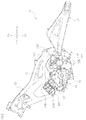
- the motorcycle 1 includes a head pipe 5 and a body frame 20 secured to the head pipe 5.
- a steering shaft (not shown) is supported on the head pipe 5, and a handlebar 7 is provided on an upper portion of the steering shaft.
- a front fork 9 is provided on a lower portion of the steering shaft.
- a front wheel 10 is supported rotatably at the lower end of the front fork 9.
- a fuel tank 3 is disposed behind the head pipe 5, and a seat 15 is disposed at the rear of the fuel tank 3. The fuel tank 3 and the seat 15 are supported by the body frame 20.
- the motorcycle 1 includes an internal combustion engine 40.
- the internal combustion engine 40 is disposed under the left main frame 22 and the right main frame 32.
- the internal combustion engine 40 is supported non-swingably by the left main frame 22 and the right main frame 32.
- each of the left main frame 22 and the right main frame 32 includes a first connecting portion 22A, a second connecting portion 22B positioned more rearward than the first connecting portion 22A, a third connecting portion 22C positioned more rearward than the second connecting portion 22B, and a fourth connecting portion 22D positioned lower than the third connecting portion 22C.
- each of the left main frame 22 and the right main frame 32 is linked to a connecting portion 80A (see Fig.
- the internal combustion engine 40 preferably is a multi-cylinder engine.
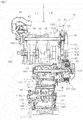
- the internal combustion engine 40 includes a crankshaft 42 extending in a transverse direction, a balancer shaft 38 positioned more frontward than the crankshaft 42, a main shaft 108 positioned more rearward than the crankshaft 42, a drive shaft 118 positioned more rearward than the main shaft 108, a clutch 100 to which torque of the crankshaft 42 is transmitted, a transmission 110, and a crankcase 48 (see Fig. 1 ) configured to accommodate these components.
- the crankcase 48 includes the upper crankcase 50 and the lower crankcase 60. As illustrated in Fig.
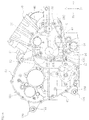
- the upper crankcase 50 and the lower crankcase 60 together define a crank chamber 45 accommodating the crankshaft 42, a clutch chamber 105 accommodating the clutch 100, a transmission chamber 115 accommodating the transmission 110, and a cam chain chamber 46 accommodating a later-described cam chain 47.
- the upper crankcase 50 and the lower crankcase 60 include the crank chamber 45, the clutch chamber 105, the transmission chamber 115, and the cam chain chamber 46.
- the transmission chamber 115 accommodates the main shaft 108 and the drive shaft 118.
- the crank chamber 45 and the clutch chamber 105 are in communication with each other.
- the crank chamber 45 and the clutch chamber 105 are in communication with each other at the rear of a third cylinder 73.
- the clutch chamber 105 is positioned to the right of the transmission chamber 115.
- the left-to-right length H1 of the transmission chamber 115 is shorter than the left-to-right length H2 of the crank chamber 45.
- the term "left-to-right length” herein means the transverse length.
- the length H1 represents the length of the transversely longest portion of the transmission chamber 115, and the length H2 represents the length of the transversely longest portion of the crank chamber 45.
- the internal combustion engine 40 includes a cylinder body 70, a cylinder head 80, and a cylinder head cover 95.
- the cylinder body 70 extends frontward and obliquely upward from the upper crankcase 50.
- the cylinder head 80 is disposed above the cylinder body 70 and joined to the cylinder body 70.
- the cylinder head cover 95 is disposed above the cylinder head 80 and joined to an end portion of the cylinder head 80.
- the cylinder body 70 and the upper crankcase 50 preferably are integrally formed with each other so as to be defined by a single monolithic member.
- the cylinder body 70 and the upper crankcase 50 may be formed of separate members, for example. It is possible that a gasket may be disposed between the cylinder head 80 and the cylinder body 70.
- the internal combustion engine 40 includes an intake valve 84 configured to open/close the passage between the combustion chamber 82 and the intake port 82, and an exhaust valve 86 configured to open/close the passage between the combustion chamber 82 and the exhaust port 85.
- the intake port 83 constitutes a portion of an intake passage 28.
- the intake passage 28 is connected to an air cleaner, which is not shown in the drawings.
- the exhaust port 85 constitutes a portion of an exhaust passage 29.
- the exhaust passage 29 includes an exhaust pipe 13 (see Fig. 1 ), which is fitted to the cylinder head 80, and a silencer 14 (see Fig. 1 ).
- each one of the combustion chambers 82 is provided with two intake ports 83 and two exhaust ports 85.
- the intake valve 84 is disposed for each of the intake ports 83, and the exhaust valve 86 is disposed for each of the exhaust ports 85. It is possible, however, that each one of the combustion chambers 82 may be provided with one intake port 82 and one exhaust port 85. It is also possible that each one of the combustion chambers 82 may be provided with different numbers of intake ports 82 and exhaust ports 85 from each other.
- an intake camshaft 84A and an exhaust camshaft 86A extending in a transverse direction are disposed between the cylinder head 80 and the cylinder head cover 95.
- the intake camshaft 84A includes intake cams 84B (see Fig. 12 ) each of which comes into contact with an upper end 84t of the intake valve 84 to operate the intake valve 84.
- the exhaust camshaft 85A includes exhaust cams 86B (see Fig. 12 ) each of which comes into contact with an upper end 86t of the exhaust valve 86 to operate the exhaust valve 86.
- a cam chain sprocket 84S is fitted to a right end portion of the intake camshaft 84A.
- the upper crankcase 50 includes a first upper partition wall 51 and a second upper partition wall 52.
- the first upper partition wall 51 separates the cam chain chamber 46 and the crank chamber 45 from each other.
- the first upper partition wall 52 includes a bottom surface 52A and separates the cam chain chamber 46 and the crank chamber 105 from each other.
- a first passage 53 is provided in the bottom surface 52A of the second upper partition wall 52. The first passage 53 allows communication between the cam chain chamber 46 and the clutch chamber 105. As illustrated in Fig.
- a second passage 54 configured to allow communication between the cam chain chamber 46 and the crank chamber 45 is provided in the first upper partition wall 51 of the upper crankcase 50.
- the second passage 54 is positioned below the cylinder body 70.
- the second passage 54 is positioned more frontward than the axial center 42C of the crankshaft 42.
- the second passage 54 is positioned more rearward than the axial center 38C of the balancer shaft 38.
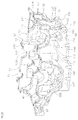
- the lower crankcase 60 includes a first lower partition wall 61 and a second lower partition wall 62. As illustrated in Fig. 8 , the first lower partition wall 61 separates the cam chain chamber 46 and the crank chamber 45 from each other. The first lower partition wall 61 is in contact with the first upper partition wall 51. The second lower partition wall 62 separates the cam chain chamber 46 and the clutch chamber 105 from each other. The second lower partition wall 62 includes a top surface 62A that is in contact with the bottom surface 52A of the second upper partition wall 52. A first passage 63, including a groove extending in a front-to-rear direction, is provided in the top surface 62A of the second lower partition wall 62. The first passage 63 allows communication between the cam chain chamber 46 and the clutch chamber 105.
- an oil passage 64 that allows communication between the cam chain chamber 46 and the crank chamber 45 is provided in the first lower partition wall 61.
- the oil in the cam chain chamber 46 passes through the oil passage 64 and flows into the crank chamber 45, and the oil is recovered in the oil pan 18 positioned below the crank chamber 45.
- the bottom surface 52A of the second upper partition wall 52 and the top surface 62A of the second lower partition wall 62 may be indirectly in contact with each other, by interposing a gasket or the like between the bottom surface 52A and the top surface 62A.
- the first passages 53 and 63 allow communication between the cam chain chamber 46 and the clutch chamber 105.
- the vertical length of the first passage 53 is longer than the vertical length of the first passage 63.
- the left-to-right length of the first passage 53 preferably is the same or substantially the same as the left-to-right length of the first passage 63.
- the vertical lengths of the first passages 53 and 63 may be equal to each other, or the vertical length of the first passage 63 may be longer than that of the first passage 53.
- the left-to-right lengths of the first passages 53 and 63 may be different from each other.
- the first passages 53 and 63 may be disposed so as to be staggered from each other in a transverse direction.
- the first passages 53 and 63 are provided respectively in the bottom surface 52A of the second upper partition wall 52 and the top surface 62A of the second lower partition wall 62. However, it is sufficient that the first passage be provided in at least one of the bottom surface 52A and the top surface 62A.
- the first passage may be configured to penetrate through at least one of the second upper partition wall 52 and the second lower partition wall 62 so as to allow communication between the cam chain chamber 46 and the clutch chamber 105.
- the upper crankcase 50 includes a first bolt insertion hole 55A and a second bolt insertion hole 55B at the respective opposite sides of the first passage 53.
- the first bolt insertion hole 55A is positioned more leftward than the second bolt insertion hole 55B.
- the diameter of the first bolt insertion hole 55A is greater than the diameter of the second bolt insertion hole 55B.
- the lower crankcase 60 includes a first bolt insertion hole 65A and a second bolt insertion hole 65B at the respective opposite sides of the first passage 63.
- the first bolt insertion hole 65A is positioned more leftward than the second bolt insertion hole 65B.
- the diameter of the first bolt insertion hole 65A is greater than the diameter of the second bolt insertion hole 65B.
- the upper crankcase 50 and the lower crankcase 60 are secured to each other preferably by bolts 56A and 56B, for example.
- the gaps P1 and P2 are the gap between the first lower partition wall 61 and the crank gear 42G that is at the axial center 42C of the crankshaft 42 and the gap between the first lower partition wall 61 and the sprocket 42S that is at the axial center 42C of the crankshaft 42, respectively.
- the internal combustion engine 40 includes an alternator 67.
- the alternator 67 is fitted to a left end portion of the crankshaft 42.
- the upper crankcase 50 and the lower crankcase 60 together define an alternator chamber 68 configured to accommodate the alternator 67.
- the alternator chamber 68 is positioned to the left of the crank chamber 45.
- a plastic gear 66 configured to drive a water pump 16 is disposed in the alternator chamber 68.
- a gear 38H is fixed to a left end portion of the balancer shaft 38. The gear 38H meshes with the plastic gear 66. Therefore, the water pump 16 interlocks with the balancer shaft 38.
- An oil passage 69P that allows communication between the alternator chamber 68 and the crank chamber 45 is located in the third lower partition wall 69B.
- the oil that has flowed from the cylinder body 70 through the first communication port 77 and the outlet 77E into the alternator chamber 68 is supplied to the plastic gear 66. Thereafter, the oil flows through the oil passage 69P into the crank chamber 45 and is recovered into the oil pan 18, which is positioned below the crank chamber 45.
- a rib 69R extending from the third lower partition wall 69B is located below the crankshaft 42.
- the cylinder body 70 includes a mounting surface 76 to be fitted to the cylinder head 80.
- the cylinder body 70 includes the first cylinder 71, the second cylinder 72, and the third cylinder 73, which are lined up in a transverse direction.
- the cam chain chamber 46 is disposed to the right of the third cylinder 73, which is the rightmost one of the cylinders.
- the cylinder body 70 includes a coolant passage 74 that surrounds the cylinders 71 to 73 and through which coolant flows.
- the cylinder body 70 includes a plurality of bolt insertion holes 75 arranged around the coolant passage 74.
- the cylinder body 70 includes a first communication port 77 and a second communication port 78.
- the cylinders 71 to 73, the coolant passage 74, the bolt insertion holes 75, the first communication port 77, and the second communication port 78 are open in the mounting surface 76.
- the second communication port 78 be disposed more rightward than the axial center 73C of the third cylinder 73, which is the rightmost one of the cylinders. It is preferable that the second communication port 78 be disposed behind the third cylinder 73, which is the rightmost one of the cylinders.
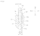
- the diameter A1 of the first communication port 77 (the inner diameter A1 of a later-described first main communication port 77A) and the diameter B1 of the second communication port 78 (the inner diameter B1 of a later-described second main communication port 78A) are greater than the diameter C1 of the bolt insertion holes 75.
- the diameter A1 of the first communication port 77 and the diameter B1 of the second communication port 78 are greater than the groove width of the coolant passage 74.
- the just-mentioned groove width is, for example, the groove width D1 of a portion of the coolant passage 74 that overlaps the first linear line L1 and/or the second linear line L2.
- the upper end 77T of the first communication port 77 is disposed lower than the upper end 78T of the second communication port 78.
- the first communication port 77 is disposed more leftward than the axial center 71C of the first cylinder 71.
- the first communication port 77 may be disposed, for example, between the axial center 71C of the first cylinder 71 and the axial center 72C of the second cylinder 72.
- the second communication port 78 is disposed more rightward than the axial center 73C of the third cylinder 73.
- the second communication port 78 may be disposed, for example, between the axial center 73C of the third cylinder 73 and the axial center 72C of the second cylinder 72.
- an oil supply port 79 is provided in the cylinder body 70.
- the oil in the oil pan 18 is supplied through the oil supply port 79 to the cylinder head 80.
- the oil supply port 79 is positioned more rearward than the first communication port 77 and more frontward than the second communication port 78.
- the oil supply port 79 is positioned more rearward than the first linear line L1.
- the oil supply port 79 is positioned more rightward than the second communication port 78.
- the cylinder head 80 includes a mounting surface 92 to be fitted to the cylinder body 70, a first passage 93, and a second passage 94.
- the first passage 93 and the second passage 94 are open in the mounting surface 92.
- the first passage 93 is in communication with the first communication port 77 of the cylinder body 70.
- the second passage 94 is in communication with the second communication port 78 of the cylinder body 70.
- the oil supply port 89 is positioned more rearward than the first passage 93 and more frontward than the second passage 94.
- the oil supply port 89 is positioned more rearward than the intake port 83.
- the oil supply port 89 is positioned to the right of the second communication port 94.
- the upper end of the second communication port 78 is open in the mounting surface 76 of the cylinder body 70, and the lower end of the second communication port 78 is open in the crank chamber 45.
- the second communication port 78 allows communication between the crank chamber 45 and the interior of the cylinder head 80.
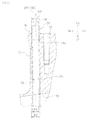
- the air in the crank chamber 45 passes through the second communication port 78, the second dowel pin 88, and the second passage 94 and flows into the cylinder head 80, as indicated by the arrow Y in Fig. 18 .
- the oil reserved in the oil pan 18 (see Fig. 1 ) is supplied to the crankshaft 42, as indicated by the arrow Z1 in Fig. 18 , by an oil pump, which is not shown in the drawings.
- a portion of the oil supplied to the crankshaft 42 is supplied to the balancer shaft 38, as indicated by the arrow Z2 in Fig. 18 .
- Another portion of the oil supplied to the crankshaft 42 is supplied to the upper crankcase 50, the oil supply port 79 of the cylinder body 70, and the oil supply port 89 of the cylinder head 80, as indicated by the arrow Z3 in Fig. 18 .
- the oil supplied to the oil supply port 89 is then supplied to the intake camshaft 84A and the exhaust camshaft 86A through a cam cap (not shown) and an oil passage 95P.
- a portion of the oil supplied to the intake camshaft 84A and the exhaust camshaft 86A circulates in the cylinder body 70, and flows into the first passage 93, as indicated by the arrow Z6 in Fig. 18 .
- the oil having flowed into the first passage 93 flows through the first dowel pin 87 and the first communication port 77 and then flows into the alternator chamber 68 (see Fig. 6 ), as indicated by the arrow Z7 in Fig. 18 , and the oil is recovered in the oil pan 18.
- the upper crankcase 50 and the cylinder body 70 preferably are integrally formed with each other so as to be defined by a single monolithic member.
- the internal combustion engine 40 may include two cylindrical dowel pins between the upper crankcase 50 and the cylinder body 70 to position the upper crankcase 50 and the cylinder body 70. One of the dowel pins is fitted into the first communication port 77, and other one of the dowel pins is fitted into the second communication port 78.
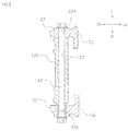
- the upper crankcase 50 includes a boss portion 120 extending transversely.
- the boss portion 120 includes a hole 122 extending in a transverse direction.
- the boss portion 120 is disposed between the left main frame 22 and the right main frame 32.
- a rod-shaped fastener 140 extending in a transverse direction is inserted through a first left insertion hole 23A located in the left main frame 22, a first right insertion hole 33A located in the right main frame 32, and the hole 122 of the boss portion 120.
- the boss portion 120 of the upper crankcase 50 is secured via the fastener 140 to the left main frame 22 and the right main frame 32.
- the boss 120 is disposed more rearward than the clutch chamber 105.
- the lower crankcase 60 includes a left boss portion 130 extending transversely direction and a right boss portion 134 extending transversely.
- the left boss portion 130 includes a hole 132 extending in a transverse direction.
- the right boss portion 134 includes a hole 136 extending in a transverse direction.
- the left boss portion 130 is disposed between the left main frame 22 and the right main frame 32.
- the right boss portion 134 is disposed between the left main frame 22 and the right main frame 32 and to the right of the left boss portion 130.
- a rod-shaped fastener 150 extending transversely is inserted through a second left insertion hole 23B located in the left main frame 22, a second right insertion hole 33B located in the right main frame 32, and the hole 132 of the left boss portion 130, and the hole 136 of the right boss portion 134.
- the left boss portion 130 of the lower crankcase 60 is secured to the left main frame 22, and the right boss portion 134 is secured to the right main frame 32.
- the upper crankcase 50 includes the boss portion 120
- the lower crankcase 60 includes the left boss portion 130 and the right boss portion 134, for example.
- the upper crankcase 50 may include the right and left boss portions, as with the lower crankcase 60
- the lower crankcase 60 may include only one boss portion, as with the upper crankcase 50.
- the left end 160L of the oil passage 160 may be positioned more rightward than the left boss portion 130 and the right end 160R of the oil passage 160 may be positioned more leftward than the right boss portion 134.
- the left end 160L of the oil passage 160 may be linked to the left boss portion 130, and the right end 160R of the oil passage 160 may be linked to the right boss portion 134.
- the oil passage 160 is disposed lower than the drive shaft 118 and higher than the left boss portion 130.
- the oil passage 160 is disposed so that, as viewed from one side of the motorcycle, the center 160C of the oil passage 160 is positioned more frontward than the center 130C of the left boss portion 130 and more rearward than the center 118C of the drive shaft 118. That said, the oil passage 160 may be disposed so that, as viewed from one side of the motorcycle, the center 160C of the oil passage 160 and the center 130C of the left boss portion 130 overlap each other. Alternatively, the oil passage 160 may be disposed so that, as viewed from one side of the motorcycle, the center 160C of the oil passage 160 overlaps the hole 132 of the left boss portion 130.
- the oil passage 160 is disposed so as to overlap the drive shaft 118, as viewed in plan of the motorcycle.
- the oil passage 160 is disposed so that, as viewed in plan of the motorcycle, a portion of the oil passage 160 overlaps a portion of the left boss portion 130 and a portion of the right boss portion 134.
- the oil passage 160 is disposed so that, as viewed from the rear of the motorcycle, a portion of the oil passage 160 overlaps a portion of a first rib 133 and a portion of a second rib 137.
- the oil passage 160 is disposed higher than the left boss portion 130 and the right boss portion 134, as illustrated in Fig.
- the first ribs 133 and the second ribs 137 extend rearward and in a vertical direction, from the rear wall 115D.
- the oil passage 160 intersects with the first ribs 133 and the second ribs 137.
- the front end portion 133A of each of the first ribs 133 is disposed more frontward than the oil passage 160.
- the oil passage 160 includes a first outer wall 162, which constitutes a portion of the outer surface of the lower crankcase 60.
- the first outer wall 162 constitutes a portion of the outer surface of the rear wall 115D of the transmission chamber 115.
- the oil passage 160 includes a second outer wall 164, which is positioned inward of the lower crankcase 60 and which constitutes a portion of the outer surface of the lower crankcase 60.
- the second outer wall 164 constitutes a portion of the rear wall 115D of the transmission chamber 115.
- oil is supplied to the first communication passage 173 through the oil groove 172 (see Fig. 26 ), which is provided in the drive shaft supporting surface 170, by an oil pump, which is not shown in the drawings.
- the oil having been supplied to the first communication passage 173 flows through the oil passage 160, the second communication passage 177, and the oil groove 176 (see Fig. 26 ), as indicated by the arrow K in Fig. 5 .
- a portion of the oil having been supplied to the oil groove 176 flows through the inside of the drive shaft 118, and is supplied to each of the gears 118G on the drive shaft 118.
- the oil passage 160 through which the oil having been supplied to the drive shaft 118 is provided only in the lower crankcase 60.
- the oil passage 160 may be provided only in the upper crankcase 50, and it may be provided in both of the upper crankcase 50 and the lower crankcase 60, for example.
- the crank chamber 45 which is in communication with the clutch chamber 105, is in communication with the cam chain chamber 46 through the oil passage 64, and the clutch chamber 105 is in communication with the cam chain chamber 46 through the first passages 53 and 63, which define respective grooves located in the bottom surface 52A of the second upper partition wall 52 and the top surface 62A of the second lower partition wall 62, as described above.
- the internal combustion engine 40 since the internal combustion engine 40 includes the first passages 53 and 63 in addition to the oil passage 64, the internal combustion engine 40 significantly reduces or prevents pressure variations in the crank chamber 45 even when the crankshaft 42 rotates at a high speed.
- the upper crankcase 50 has the second passage 54, which is located in the first upper partition wall 51 and which allows communication between the cam chain chamber 46 and the crank chamber 45. This prevents the pressure difference between the cam chain chamber 46 and the crank chamber 45 from increasing. As a result, the oil circulation performance from the cam chain chamber 46 to the crank chamber 45 is enhanced.
- the first passage 53 is preferably located in the bottom surface 52A of the second upper partition wall 52, and the first passage 63 preferably is located in the top surface 62A of the second lower partition wall 62, as illustrated in Figs. 7 and 8 .
- This further prevents the pressure difference between the cam chain chamber 46 and the crank chamber 45 from increasing. As a result, the oil circulation performance from the cam chain chamber 46 to the crank chamber 45 is further enhanced.
- the upper crankcase 50 includes, at respective opposite sides of the first passage 53, the first bolt insertion hole 55A and the second bolt insertion hole 55B in which the bolts 56A and 56B (see Fig. 16 ) configured to secure the upper crankcase 50 and the lower crankcase 60 to each other are inserted, respectively
- the lower crankcase 60 includes, at respective opposite sides of the first passage 63, the first bolt insertion hole 65A and the second bolt insertion hole 65B in which the bolts 56A and 56B (see Fig. 16 ) configured to secure the upper crankcase 50 and the lower crankcase 60 to each other are inserted, respectively.
- the first passage 63 has a high degree of freedom in layout, so it is capable of being located between the first bolt insertion hole 65A and the second bolt insertion hole 65B in which the bolts 56A and 56B are inserted respectively.
- the upper crankcase 50 and the cylinder body 70 preferably are integrally formed with each other so as to be defined by a single monolithic member, as illustrated in Fig. 14 .
- the cylinder body 70 preferably includes a plurality of cylinders 71 to 73 therein, as illustrated in Fig. 9 .
- the internal combustion engine 40 including a plurality of cylinders 71 to 73 exhibits less pressure variations that occur in the crank chamber 45 because of high speed rotation of the crankshaft 42, compared to an internal combustion engine having only one cylinder. Therefore, the internal combustion engine 40 achieves the advantageous effects obtained by using the configuration in which the first passages 53 and 63 are located in the bottom surface 52A of the second upper partition wall 52 and in the top surface 62A of the second lower partition wall 62 especially significantly.
- the internal combustion engine 40 preferably includes a crank gear 42G provided on the crankshaft 42 and accommodated in the crank chamber 45, and a cam sprocket 42S provided on one end of the crankshaft 42 and accommodated in the cam chain chamber 46.
- a gap P1 between the crank gear 42G and the first lower partition wall 61 is smaller than a gap P2 between the cam sprocket 42S and the first lower partition wall 61.
Landscapes
- Engineering & Computer Science (AREA)
- Mechanical Engineering (AREA)
- General Engineering & Computer Science (AREA)
- Lubrication Of Internal Combustion Engines (AREA)
- Cylinder Crankcases Of Internal Combustion Engines (AREA)
- Lubrication Details And Ventilation Of Internal Combustion Engines (AREA)
- Chemical & Material Sciences (AREA)
- Combustion & Propulsion (AREA)
Claims (9)
- Verbrennungsmotor (40), der umfasst:eine Kurbelwelle (42);eine Kupplung (100), die so eingerichtet ist, dass sie Drehmoment von der Kurbelwelle (42) empfängt;eine Steuerkette (47), die in Eingriff mit der Kurbelwelle (42) ist;ein oberes Kurbelgehäuse (50), das oberhalb der Kurbelwelle (42) angeordnet ist;ein unteres Kurbelgehäuse (60), das unterhalb der Kurbelwelle (42) angeordnet und mit dem oberen Kurbelgehäuse (50) verbunden ist;wobei das obere Kurbelgehäuse (50) und das untere Kurbelgehäuse (60) eine Kurbel-Kammer (45), die die Kurbelwelle (42) aufnimmt, eine Kupplungs-Kammer (105), die die Kupplung (100) aufnimmt und in Verbindung mit der Kurbel-Kammer (45) steht, sowie eine Steuerketten-Kammer (46) einschließen, die einen Abschnitt der Steuerkette (47) aufnimmt;das obere Kurbelgehäuse (50) eine erste obere Trennwand (51), die die Steuerketten-Kammer (46) und die Kurbel-Kammer (45) voneinander trennt, sowie eine zweite obere Trennwand (52) einschließt, die eine untere Fläche (52A) enthält und die Steuerketten-Kammer (46) und die Kupplungs-Kammer (105) voneinander trennt;das untere Kurbelgehäuse (60) eine erste untere Trennwand (61), die in Kontakt mit der ersten oberen Trennwand (51) ist und die Steuerketten-Kammer (46) und die Kurbel-Kammer (45) voneinander trennt, sowie eine zweite untere Trennwand (62) einschließt,die eine obere Fläche (62A) enthält, die in Kontakt mit der unteren Fläche (52A) der zweiten oberen Trennwand (52) ist und die Steuerketten-Kammer (46) und die Kupplungs-Kammer (105) voneinander trennt;einen Ölkanal (64), der sich in der ersten unteren Trennwand (61) befindet und so eingerichtet ist, dass er Verbindung zwischen der Steuerketten-Kammer (46) und der Kurbel-Kammer (45) zulässt und Öl von der Steuerketten-Kammer (46) zu der Kurbel-Kammer (45) leitet;eine Ölwanne (18), die unterhalb des unteren Kurbelgehäuses (60) angeordnet und so eingerichtet ist, dass sie Öl aus der Kurbel-Kammer (45) zurückgewinnt; undeinen ersten Kanal (53, 63), der eine Nut enthält, die in der unteren Fläche (52A) der zweiten oberen Trennwand (52) oder/und der oberen Fläche (62A) der zweiten unteren Trennwand (62) vorhanden ist und so eingerichtet ist, dass er Verbindung zwischen der Steuerketten-Kammer (46) und der Kupplungs-Kammer (105) zulässt.
- Verbrennungsmotor nach Anspruch 1, wobei das obere Kurbelgehäuse (50) einen zweiten Kanal (54) enthält, der in der ersten oberen Trennwand (51) vorhanden und so eingerichtet ist, dass er Verbindung zwischen der Steuerketten-Kammer (46) und der Kurbel-Kammer (45) zulässt.
- Verbrennungsmotor nach Anspruch 1 oder 2, wobei der erste Kanal (53, 63) in der unteren Fläche (52A) der zweiten oberen Trennwand (52) und in der oberen Fläche (62A) der zweiten unteren Trennwand (62) vorhanden ist.
- Verbrennungsmotor nach einem der Ansprüche 1 bis 3, wobei das obere Kurbelgehäuse (50) und das untere Kurbelgehäuse (60) jeweils zwei Löcher (55A, 65A, 55B, 65B) einschließen, die jeweils so eingerichtet sind, dass sie die Schraube (56A, 56B) zum Befestigen des oberen Kurbelgehäuses (50) und des unteren Kurbelgehäuses (60) aneinander aufnehmen, und sich die zwei Löcher (55A, 65A, 55B, 65B) an jeweiligen einander gegenüberliegenden Seiten des ersten Kanals (53, 63) befinden.
- Verbrennungsmotor nach einem der Ansprüche 1 bis 4, der des Weiteren umfasst:einen Zylinderkörper (70), der sich oberhalb oder schräg oberhalb des oberen Kurbelgehäuses (50) erstreckt; sowieeinen Zylinderkopf (80), der oberhalb des Zylinderkörpers (70) angeordnet und mit dem Zylinderkörper (70) verbunden ist; wobeider Zylinderkörper (70) einen dritten Kanal (78) einschließt, der so eingerichtet ist, dass er Verbindung zwischen der Kurbel-Kammer (45) und einem Innenraum des Zylinderkopfes (80) zulässt.
- Verbrennungsmotor nach Anspruch 5, wobei das obere Kurbelgehäuse (50) und der Zylinderkörper (70) integral miteinander ausgebildet sind.
- Verbrennungsmotor nach Anspruch 5 oder 6, wobei der Zylinderkörper (70) eine Vielzahl von Zylindern (71, 72, 73) enthält.
- Verbrennungsmotor nach einem der Ansprüche 1 bis 7, der des Weiteren umfasst:ein Kurbelrad (42G), das an der Kurbelwelle (42) vorhanden und in der Kurbel-Kammer (45) aufgenommen ist; undein Nockenwellenrad (42S), das an einem Ende der Kurbelwelle (42) vorhanden und in der Steuerketten-Kammer (46) aufgenommen ist; wobeiein Zwischenraum (P1) zwischen dem Kurbelrad (42G) und der ersten unteren Trennwand (61) kleiner ist als ein Zwischenraum (P2) zwischen dem Nockenwellenrad (42S) und der ersten unteren Trennwand (61).
- Motorrad (1), das einen Verbrennungsmotor (40) nach einem der Ansprüche 1 bis 8 umfasst.
Applications Claiming Priority (1)
| Application Number | Priority Date | Filing Date | Title |
|---|---|---|---|
| JP2013108642A JP2014227924A (ja) | 2013-05-23 | 2013-05-23 | 内燃機関およびそれを備えた自動二輪車 |
Publications (3)
| Publication Number | Publication Date |
|---|---|
| EP2806120A2 EP2806120A2 (de) | 2014-11-26 |
| EP2806120A3 EP2806120A3 (de) | 2015-03-25 |
| EP2806120B1 true EP2806120B1 (de) | 2016-08-24 |
Family
ID=50542840
Family Applications (1)
| Application Number | Title | Priority Date | Filing Date |
|---|---|---|---|
| EP14165176.0A Active EP2806120B1 (de) | 2013-05-23 | 2014-04-17 | Verbrennungsmotor und mit dem Motor ausgestattetes Motorrad |
Country Status (4)
| Country | Link |
|---|---|
| US (1) | US9200549B2 (de) |
| EP (1) | EP2806120B1 (de) |
| JP (1) | JP2014227924A (de) |
| ES (1) | ES2592164T3 (de) |
Families Citing this family (5)
| Publication number | Priority date | Publication date | Assignee | Title |
|---|---|---|---|---|
| USD781920S1 (en) * | 2016-04-04 | 2017-03-21 | Zhejiang Yongkang Top IMP | Engine |
| USD927802S1 (en) * | 2019-11-25 | 2021-08-10 | Fna Group, Inc. | Pressure washer |
| WO2021117217A1 (ja) * | 2019-12-13 | 2021-06-17 | ヤマハ発動機株式会社 | ストラドルドビークル |
| CN112832920A (zh) * | 2020-12-31 | 2021-05-25 | 浙江春风动力股份有限公司 | 发动机曲轴箱及其制造方法 |
| CN113074031B (zh) * | 2021-03-25 | 2022-11-18 | 永康市南天工贸有限公司 | 一种发动机的润滑系统、使用方法及园林设备 |
Family Cites Families (10)
| Publication number | Priority date | Publication date | Assignee | Title |
|---|---|---|---|---|
| US5092292A (en) * | 1989-01-31 | 1992-03-03 | Suzuki Jidosha Kogyo Kabushiki Kaisha | Lubricating apparatus of motorcycle engine |
| JP2005061274A (ja) * | 2003-08-08 | 2005-03-10 | Yamaha Motor Co Ltd | 車両用エンジン |
| JP4523533B2 (ja) * | 2005-09-30 | 2010-08-11 | 本田技研工業株式会社 | 小型車両用エンジンの潤滑装置 |
| JP4757060B2 (ja) | 2006-02-28 | 2011-08-24 | 本田技研工業株式会社 | 自動二輪車用内燃機関の補機配置構造 |
| JP2008223596A (ja) * | 2007-03-13 | 2008-09-25 | Yamaha Motor Co Ltd | 内燃機関およびそれを備えた車両 |
| TWM325381U (en) | 2007-06-08 | 2008-01-11 | Jenn Feng Ind Co Ltd | Lubricating device for four cycle engine |
| JP3154536U (ja) * | 2008-08-08 | 2009-10-22 | ヤマハ発動機株式会社 | 鞍乗り型車両 |
| JP2011038437A (ja) | 2009-08-07 | 2011-02-24 | Suzuki Motor Corp | 内燃機関 |
| JP5667366B2 (ja) * | 2010-02-12 | 2015-02-12 | 本田技研工業株式会社 | 内燃機関のクランクケース構造 |
| US8714124B2 (en) * | 2011-11-25 | 2014-05-06 | Honda Motor Co., Ltd. | Cover structure for internal combustion engine |
-
2013
- 2013-05-23 JP JP2013108642A patent/JP2014227924A/ja active Pending
-
2014
- 2014-04-17 EP EP14165176.0A patent/EP2806120B1/de active Active
- 2014-04-17 ES ES14165176.0T patent/ES2592164T3/es active Active
- 2014-04-29 US US14/264,219 patent/US9200549B2/en active Active
Also Published As
| Publication number | Publication date |
|---|---|
| EP2806120A3 (de) | 2015-03-25 |
| US20140345551A1 (en) | 2014-11-27 |
| ES2592164T3 (es) | 2016-11-28 |
| US9200549B2 (en) | 2015-12-01 |
| JP2014227924A (ja) | 2014-12-08 |
| EP2806120A2 (de) | 2014-11-26 |
Similar Documents
| Publication | Publication Date | Title |
|---|---|---|
| US7448355B2 (en) | Integrated power unit including split crankcase with reinforced fastening arrangement, and vehicle including same | |
| AU2013205955B2 (en) | Water cooled internal combustion engine for vehicle | |
| EP2806120B1 (de) | Verbrennungsmotor und mit dem Motor ausgestattetes Motorrad | |
| US20150083068A1 (en) | Internal combustion engine | |
| EP2868879B1 (de) | Motor und mit dem Motor ausgestatteter Grätschsitzfahrzeug | |
| US7216615B2 (en) | Engine device for motorcycles | |
| JP2001280111A (ja) | 内燃機関の潤滑構造 | |
| JP2004225572A (ja) | 車両用エンジン | |
| EP2816213B1 (de) | Motorrad | |
| JP6623778B2 (ja) | 内燃機関の冷却構造 | |
| JP5048618B2 (ja) | 4サイクル空油冷エンジン | |
| US7201119B2 (en) | Vehicular power unit | |
| US9988978B2 (en) | Four-cycle multi-cylinder engine | |
| JP6769537B2 (ja) | 内燃機関の冷却構造 | |
| EP2806121B1 (de) | Motorrad | |
| US7874949B2 (en) | Power unit with auxiliary machine driving transmission mechanism | |
| US6848411B2 (en) | Secondary balancer of vertical engine of outboard motor | |
| US20050045141A1 (en) | In-line multicylinder combustion engine | |
| US7267095B2 (en) | Power unit having crankcase to which auxiliary machine is fitted, and motorcycle having power unit | |
| JP6631264B2 (ja) | 内燃機関の冷却構造 | |
| JP2002242632A (ja) | 船外機 | |
| JP2002240787A (ja) | 船外機 | |
| JP2020165358A (ja) | 内燃機関 | |
| JP2006307826A (ja) | 車両用パワーユニット |
Legal Events
| Date | Code | Title | Description |
|---|---|---|---|
| PUAI | Public reference made under article 153(3) epc to a published international application that has entered the european phase |
Free format text: ORIGINAL CODE: 0009012 |
|
| 17P | Request for examination filed |
Effective date: 20140417 |
|
| AK | Designated contracting states |
Kind code of ref document: A2 Designated state(s): AL AT BE BG CH CY CZ DE DK EE ES FI FR GB GR HR HU IE IS IT LI LT LU LV MC MK MT NL NO PL PT RO RS SE SI SK SM TR |
|
| AX | Request for extension of the european patent |
Extension state: BA ME |
|
| PUAL | Search report despatched |
Free format text: ORIGINAL CODE: 0009013 |
|
| AK | Designated contracting states |
Kind code of ref document: A3 Designated state(s): AL AT BE BG CH CY CZ DE DK EE ES FI FR GB GR HR HU IE IS IT LI LT LU LV MC MK MT NL NO PL PT RO RS SE SI SK SM TR |
|
| AX | Request for extension of the european patent |
Extension state: BA ME |
|
| RIC1 | Information provided on ipc code assigned before grant |
Ipc: F01M 1/00 20060101AFI20150216BHEP Ipc: F02F 7/00 20060101ALI20150216BHEP |
|
| R17P | Request for examination filed (corrected) |
Effective date: 20150924 |
|
| RBV | Designated contracting states (corrected) |
Designated state(s): AL AT BE BG CH CY CZ DE DK EE ES FI FR GB GR HR HU IE IS IT LI LT LU LV MC MK MT NL NO PL PT RO RS SE SI SK SM TR |
|
| GRAP | Despatch of communication of intention to grant a patent |
Free format text: ORIGINAL CODE: EPIDOSNIGR1 |
|
| RIC1 | Information provided on ipc code assigned before grant |
Ipc: F01M 1/00 20060101AFI20160331BHEP Ipc: F02F 7/00 20060101ALI20160331BHEP |
|
| INTG | Intention to grant announced |
Effective date: 20160425 |
|
| GRAS | Grant fee paid |
Free format text: ORIGINAL CODE: EPIDOSNIGR3 |
|
| GRAA | (expected) grant |
Free format text: ORIGINAL CODE: 0009210 |
|
| AK | Designated contracting states |
Kind code of ref document: B1 Designated state(s): AL AT BE BG CH CY CZ DE DK EE ES FI FR GB GR HR HU IE IS IT LI LT LU LV MC MK MT NL NO PL PT RO RS SE SI SK SM TR |
|
| REG | Reference to a national code |
Ref country code: GB Ref legal event code: FG4D |
|
| REG | Reference to a national code |
Ref country code: CH Ref legal event code: EP |
|
| REG | Reference to a national code |
Ref country code: AT Ref legal event code: REF Ref document number: 823314 Country of ref document: AT Kind code of ref document: T Effective date: 20160915 |
|
| REG | Reference to a national code |
Ref country code: IE Ref legal event code: FG4D |
|
| REG | Reference to a national code |
Ref country code: DE Ref legal event code: R096 Ref document number: 602014003187 Country of ref document: DE |
|
| REG | Reference to a national code |
Ref country code: ES Ref legal event code: FG2A Ref document number: 2592164 Country of ref document: ES Kind code of ref document: T3 Effective date: 20161128 |
|
| REG | Reference to a national code |
Ref country code: LT Ref legal event code: MG4D |
|
| REG | Reference to a national code |
Ref country code: NL Ref legal event code: MP Effective date: 20160824 |
|
| REG | Reference to a national code |
Ref country code: AT Ref legal event code: MK05 Ref document number: 823314 Country of ref document: AT Kind code of ref document: T Effective date: 20160824 |
|
| PG25 | Lapsed in a contracting state [announced via postgrant information from national office to epo] |
Ref country code: FI Free format text: LAPSE BECAUSE OF FAILURE TO SUBMIT A TRANSLATION OF THE DESCRIPTION OR TO PAY THE FEE WITHIN THE PRESCRIBED TIME-LIMIT Effective date: 20160824 Ref country code: NL Free format text: LAPSE BECAUSE OF FAILURE TO SUBMIT A TRANSLATION OF THE DESCRIPTION OR TO PAY THE FEE WITHIN THE PRESCRIBED TIME-LIMIT Effective date: 20160824 Ref country code: HR Free format text: LAPSE BECAUSE OF FAILURE TO SUBMIT A TRANSLATION OF THE DESCRIPTION OR TO PAY THE FEE WITHIN THE PRESCRIBED TIME-LIMIT Effective date: 20160824 Ref country code: NO Free format text: LAPSE BECAUSE OF FAILURE TO SUBMIT A TRANSLATION OF THE DESCRIPTION OR TO PAY THE FEE WITHIN THE PRESCRIBED TIME-LIMIT Effective date: 20161124 Ref country code: RS Free format text: LAPSE BECAUSE OF FAILURE TO SUBMIT A TRANSLATION OF THE DESCRIPTION OR TO PAY THE FEE WITHIN THE PRESCRIBED TIME-LIMIT Effective date: 20160824 Ref country code: LT Free format text: LAPSE BECAUSE OF FAILURE TO SUBMIT A TRANSLATION OF THE DESCRIPTION OR TO PAY THE FEE WITHIN THE PRESCRIBED TIME-LIMIT Effective date: 20160824 |
|
| PG25 | Lapsed in a contracting state [announced via postgrant information from national office to epo] |
Ref country code: SE Free format text: LAPSE BECAUSE OF FAILURE TO SUBMIT A TRANSLATION OF THE DESCRIPTION OR TO PAY THE FEE WITHIN THE PRESCRIBED TIME-LIMIT Effective date: 20160824 Ref country code: LV Free format text: LAPSE BECAUSE OF FAILURE TO SUBMIT A TRANSLATION OF THE DESCRIPTION OR TO PAY THE FEE WITHIN THE PRESCRIBED TIME-LIMIT Effective date: 20160824 Ref country code: AT Free format text: LAPSE BECAUSE OF FAILURE TO SUBMIT A TRANSLATION OF THE DESCRIPTION OR TO PAY THE FEE WITHIN THE PRESCRIBED TIME-LIMIT Effective date: 20160824 Ref country code: GR Free format text: LAPSE BECAUSE OF FAILURE TO SUBMIT A TRANSLATION OF THE DESCRIPTION OR TO PAY THE FEE WITHIN THE PRESCRIBED TIME-LIMIT Effective date: 20161125 Ref country code: PT Free format text: LAPSE BECAUSE OF FAILURE TO SUBMIT A TRANSLATION OF THE DESCRIPTION OR TO PAY THE FEE WITHIN THE PRESCRIBED TIME-LIMIT Effective date: 20161226 |
|
| REG | Reference to a national code |
Ref country code: FR Ref legal event code: PLFP Year of fee payment: 4 |
|
| PG25 | Lapsed in a contracting state [announced via postgrant information from national office to epo] |
Ref country code: RO Free format text: LAPSE BECAUSE OF FAILURE TO SUBMIT A TRANSLATION OF THE DESCRIPTION OR TO PAY THE FEE WITHIN THE PRESCRIBED TIME-LIMIT Effective date: 20160824 Ref country code: EE Free format text: LAPSE BECAUSE OF FAILURE TO SUBMIT A TRANSLATION OF THE DESCRIPTION OR TO PAY THE FEE WITHIN THE PRESCRIBED TIME-LIMIT Effective date: 20160824 |
|
| REG | Reference to a national code |
Ref country code: DE Ref legal event code: R097 Ref document number: 602014003187 Country of ref document: DE |
|
| PG25 | Lapsed in a contracting state [announced via postgrant information from national office to epo] |
Ref country code: BG Free format text: LAPSE BECAUSE OF FAILURE TO SUBMIT A TRANSLATION OF THE DESCRIPTION OR TO PAY THE FEE WITHIN THE PRESCRIBED TIME-LIMIT Effective date: 20161124 Ref country code: DK Free format text: LAPSE BECAUSE OF FAILURE TO SUBMIT A TRANSLATION OF THE DESCRIPTION OR TO PAY THE FEE WITHIN THE PRESCRIBED TIME-LIMIT Effective date: 20160824 Ref country code: PL Free format text: LAPSE BECAUSE OF FAILURE TO SUBMIT A TRANSLATION OF THE DESCRIPTION OR TO PAY THE FEE WITHIN THE PRESCRIBED TIME-LIMIT Effective date: 20160824 Ref country code: SK Free format text: LAPSE BECAUSE OF FAILURE TO SUBMIT A TRANSLATION OF THE DESCRIPTION OR TO PAY THE FEE WITHIN THE PRESCRIBED TIME-LIMIT Effective date: 20160824 Ref country code: CZ Free format text: LAPSE BECAUSE OF FAILURE TO SUBMIT A TRANSLATION OF THE DESCRIPTION OR TO PAY THE FEE WITHIN THE PRESCRIBED TIME-LIMIT Effective date: 20160824 Ref country code: SM Free format text: LAPSE BECAUSE OF FAILURE TO SUBMIT A TRANSLATION OF THE DESCRIPTION OR TO PAY THE FEE WITHIN THE PRESCRIBED TIME-LIMIT Effective date: 20160824 Ref country code: BE Free format text: LAPSE BECAUSE OF FAILURE TO SUBMIT A TRANSLATION OF THE DESCRIPTION OR TO PAY THE FEE WITHIN THE PRESCRIBED TIME-LIMIT Effective date: 20160824 |
|
| PLBE | No opposition filed within time limit |
Free format text: ORIGINAL CODE: 0009261 |
|
| STAA | Information on the status of an ep patent application or granted ep patent |
Free format text: STATUS: NO OPPOSITION FILED WITHIN TIME LIMIT |
|
| 26N | No opposition filed |
Effective date: 20170526 |
|
| PG25 | Lapsed in a contracting state [announced via postgrant information from national office to epo] |
Ref country code: SI Free format text: LAPSE BECAUSE OF FAILURE TO SUBMIT A TRANSLATION OF THE DESCRIPTION OR TO PAY THE FEE WITHIN THE PRESCRIBED TIME-LIMIT Effective date: 20160824 |
|
| REG | Reference to a national code |
Ref country code: CH Ref legal event code: PL |
|
| REG | Reference to a national code |
Ref country code: IE Ref legal event code: MM4A |
|
| PG25 | Lapsed in a contracting state [announced via postgrant information from national office to epo] |
Ref country code: MC Free format text: LAPSE BECAUSE OF FAILURE TO SUBMIT A TRANSLATION OF THE DESCRIPTION OR TO PAY THE FEE WITHIN THE PRESCRIBED TIME-LIMIT Effective date: 20160824 |
|
| PG25 | Lapsed in a contracting state [announced via postgrant information from national office to epo] |
Ref country code: LU Free format text: LAPSE BECAUSE OF NON-PAYMENT OF DUE FEES Effective date: 20170417 Ref country code: CH Free format text: LAPSE BECAUSE OF NON-PAYMENT OF DUE FEES Effective date: 20170430 Ref country code: LI Free format text: LAPSE BECAUSE OF NON-PAYMENT OF DUE FEES Effective date: 20170430 |
|
| REG | Reference to a national code |
Ref country code: FR Ref legal event code: PLFP Year of fee payment: 5 |
|
| PG25 | Lapsed in a contracting state [announced via postgrant information from national office to epo] |
Ref country code: IE Free format text: LAPSE BECAUSE OF NON-PAYMENT OF DUE FEES Effective date: 20170417 |
|
| PG25 | Lapsed in a contracting state [announced via postgrant information from national office to epo] |
Ref country code: MT Free format text: LAPSE BECAUSE OF NON-PAYMENT OF DUE FEES Effective date: 20170417 |
|
| PG25 | Lapsed in a contracting state [announced via postgrant information from national office to epo] |
Ref country code: AL Free format text: LAPSE BECAUSE OF FAILURE TO SUBMIT A TRANSLATION OF THE DESCRIPTION OR TO PAY THE FEE WITHIN THE PRESCRIBED TIME-LIMIT Effective date: 20160824 |
|
| PG25 | Lapsed in a contracting state [announced via postgrant information from national office to epo] |
Ref country code: HU Free format text: LAPSE BECAUSE OF FAILURE TO SUBMIT A TRANSLATION OF THE DESCRIPTION OR TO PAY THE FEE WITHIN THE PRESCRIBED TIME-LIMIT; INVALID AB INITIO Effective date: 20140417 |
|
| PG25 | Lapsed in a contracting state [announced via postgrant information from national office to epo] |
Ref country code: CY Free format text: LAPSE BECAUSE OF FAILURE TO SUBMIT A TRANSLATION OF THE DESCRIPTION OR TO PAY THE FEE WITHIN THE PRESCRIBED TIME-LIMIT Effective date: 20160824 |
|
| PG25 | Lapsed in a contracting state [announced via postgrant information from national office to epo] |
Ref country code: MK Free format text: LAPSE BECAUSE OF FAILURE TO SUBMIT A TRANSLATION OF THE DESCRIPTION OR TO PAY THE FEE WITHIN THE PRESCRIBED TIME-LIMIT Effective date: 20160824 |
|
| PG25 | Lapsed in a contracting state [announced via postgrant information from national office to epo] |
Ref country code: TR Free format text: LAPSE BECAUSE OF FAILURE TO SUBMIT A TRANSLATION OF THE DESCRIPTION OR TO PAY THE FEE WITHIN THE PRESCRIBED TIME-LIMIT Effective date: 20160824 |
|
| PG25 | Lapsed in a contracting state [announced via postgrant information from national office to epo] |
Ref country code: IS Free format text: LAPSE BECAUSE OF FAILURE TO SUBMIT A TRANSLATION OF THE DESCRIPTION OR TO PAY THE FEE WITHIN THE PRESCRIBED TIME-LIMIT Effective date: 20161224 |
|
| P01 | Opt-out of the competence of the unified patent court (upc) registered |
Effective date: 20230527 |
|
| PGFP | Annual fee paid to national office [announced via postgrant information from national office to epo] |
Ref country code: DE Payment date: 20250422 Year of fee payment: 12 |
|
| PGFP | Annual fee paid to national office [announced via postgrant information from national office to epo] |
Ref country code: ES Payment date: 20250529 Year of fee payment: 12 |
|
| PGFP | Annual fee paid to national office [announced via postgrant information from national office to epo] |
Ref country code: IT Payment date: 20250424 Year of fee payment: 12 |
|
| PGFP | Annual fee paid to national office [announced via postgrant information from national office to epo] |
Ref country code: FR Payment date: 20250425 Year of fee payment: 12 |
|
| PGFP | Annual fee paid to national office [announced via postgrant information from national office to epo] |
Ref country code: GB Payment date: 20260306 Year of fee payment: 13 |