EP2806224A2 - Klimaanlage - Google Patents
Klimaanlage Download PDFInfo
- Publication number
- EP2806224A2 EP2806224A2 EP14168844.0A EP14168844A EP2806224A2 EP 2806224 A2 EP2806224 A2 EP 2806224A2 EP 14168844 A EP14168844 A EP 14168844A EP 2806224 A2 EP2806224 A2 EP 2806224A2
- Authority
- EP
- European Patent Office
- Prior art keywords
- microphone
- air conditioner
- housing
- wall
- housing body
- Prior art date
- Legal status (The legal status is an assumption and is not a legal conclusion. Google has not performed a legal analysis and makes no representation as to the accuracy of the status listed.)
- Granted
Links
Images



Classifications
-
- H—ELECTRICITY
- H04—ELECTRIC COMMUNICATION TECHNIQUE
- H04R—LOUDSPEAKERS, MICROPHONES, GRAMOPHONE PICK-UPS OR LIKE ACOUSTIC ELECTROMECHANICAL TRANSDUCERS; ELECTRIC HEARING AIDS; PUBLIC ADDRESS SYSTEMS
- H04R1/00—Details of transducers, loudspeakers or microphones
- H04R1/08—Mouthpieces; Microphones; Attachments therefor
-
- F—MECHANICAL ENGINEERING; LIGHTING; HEATING; WEAPONS; BLASTING
- F24—HEATING; RANGES; VENTILATING
- F24F—AIR-CONDITIONING; AIR-HUMIDIFICATION; VENTILATION; USE OF AIR CURRENTS FOR SCREENING
- F24F11/00—Control or safety arrangements
- F24F11/30—Control or safety arrangements for purposes related to the operation of the system, e.g. for safety or monitoring
-
- F—MECHANICAL ENGINEERING; LIGHTING; HEATING; WEAPONS; BLASTING
- F24—HEATING; RANGES; VENTILATING
- F24F—AIR-CONDITIONING; AIR-HUMIDIFICATION; VENTILATION; USE OF AIR CURRENTS FOR SCREENING
- F24F11/00—Control or safety arrangements
- F24F11/50—Control or safety arrangements characterised by user interfaces or communication
- F24F11/56—Remote control
-
- F—MECHANICAL ENGINEERING; LIGHTING; HEATING; WEAPONS; BLASTING
- F24—HEATING; RANGES; VENTILATING
- F24F—AIR-CONDITIONING; AIR-HUMIDIFICATION; VENTILATION; USE OF AIR CURRENTS FOR SCREENING
- F24F13/00—Details common to, or for air-conditioning, air-humidification, ventilation or use of air currents for screening
- F24F13/20—Casings or covers
-
- H—ELECTRICITY
- H04—ELECTRIC COMMUNICATION TECHNIQUE
- H04R—LOUDSPEAKERS, MICROPHONES, GRAMOPHONE PICK-UPS OR LIKE ACOUSTIC ELECTROMECHANICAL TRANSDUCERS; ELECTRIC HEARING AIDS; PUBLIC ADDRESS SYSTEMS
- H04R1/00—Details of transducers, loudspeakers or microphones
- H04R1/02—Casings; Cabinets ; Supports therefor; Mountings therein
- H04R1/028—Casings; Cabinets ; Supports therefor; Mountings therein associated with devices performing functions other than acoustics, e.g. electric candles
-
- F—MECHANICAL ENGINEERING; LIGHTING; HEATING; WEAPONS; BLASTING
- F24—HEATING; RANGES; VENTILATING
- F24F—AIR-CONDITIONING; AIR-HUMIDIFICATION; VENTILATION; USE OF AIR CURRENTS FOR SCREENING
- F24F13/00—Details common to, or for air-conditioning, air-humidification, ventilation or use of air currents for screening
- F24F13/24—Means for preventing or suppressing noise
- F24F2013/242—Sound-absorbing material
-
- F—MECHANICAL ENGINEERING; LIGHTING; HEATING; WEAPONS; BLASTING
- F24—HEATING; RANGES; VENTILATING
- F24F—AIR-CONDITIONING; AIR-HUMIDIFICATION; VENTILATION; USE OF AIR CURRENTS FOR SCREENING
- F24F2110/00—Control inputs relating to air properties
-
- F—MECHANICAL ENGINEERING; LIGHTING; HEATING; WEAPONS; BLASTING
- F24—HEATING; RANGES; VENTILATING
- F24F—AIR-CONDITIONING; AIR-HUMIDIFICATION; VENTILATION; USE OF AIR CURRENTS FOR SCREENING
- F24F2130/00—Control inputs relating to environmental factors not covered by group F24F2110/00
- F24F2130/40—Noise
Definitions
- the present disclosure relates to an air conditioner.
- Air conditioners are electric home appliances for maintaining indoor air as being most appropriate for the use or purpose. In other words, air conditioners control a room to be cooled in summer and to be warmed in winter, controls indoor humidity, and controls indoor air to be pleasant and cleaned. Air conditioners, in which a cooling cycle is driven, may include a compressor, a condenser, an expander, and a vaporizer.
- air conditioners there are formed an inlet for sucking the air in an indoor space, a heat exchanger for heat-exchanging the air sucked through the inlet, and an outlet for discharging the air heat-exchanged by the heat exchanger into the indoor space.
- air conditioners may be provided with a ventilating fan for generating an air flow from the inlet to the outlet.
- General air conditioners are configured to allow a user to directly operate an input unit included therein to select a certain mode thereof or to use a remote control in a location separate from air conditioners.
- Embodiments provide an air conditioner easily collecting voices.
- an air conditioner includes a body including an outlet and a voice collecting device provided on one side of the outlet and including a microphone collecting voices.
- the voice collecting device includes a housing body including an opening in which the microphone is installed, a housing cover provided on one side of the housing body, and a noise insulation space defined by the housing body and the housing cover and including previously determined width and height. Also, the microphone is disposed in the noise insulation space.
- the housing body may include a first wall including the opening and a second wall extending from the first wall and defining a width of the noise insulation space in one direction.
- the second wall may be provided as a plurality thereof, and the plurality of second walls may be coupled with the housing cover.
- the voice collecting device may further include a supporting member coupled with one side of the first wall, supporting the microphone on the housing body, and formed with an insertion hole to which the microphone is fixed.
- the supporting member may include a second coupling hole provided on at least one side of the insertion hole and aligned with a first coupling hole of a housing.
- the microphone may be disposed adjacent or closely attached to the opening.
- the microphone may be provided on an inside of the first wall, and a front of the microphone may form the same surface of an inner circumferential surface of the first wall.
- the voice collecting device may further include a coupling unit coupled with the body to be separable, and a mounting part supporting the housing body may be provided in the coupling unit.
- the housing body may be inserted into the mounting part and extends in one direction and another direction of the mounting part.
- the microphone may be disposed to be separate from the second wall by a set distance.
- a width W and a height H of the housing may be formed to be greater than a width and a height of the microphone, respectively.
- the microphone may be disposed to be separate from the housing cover by a set distance.
- the body may include a side panel forming a lateral external shape of the air conditioner, and the voice collecting device may be provided on the side panel.
- the side panel may include a dent part dent toward an inside of the body and containing the housing and a settling part forming one surface of the dent part and allowing the housing cover to be settled thereon.
- an air conditioner in another embodiment, includes a panel including an outlet, a housing coupled with the panel, and a microphone contained in the housing and collecting voices.
- the housing includes a plurality of walls separate from the microphone and insulating noises not to be transferred to the microphone.
- the plurality of walls may include a first wall including an opening in which the microphone is installed and a second wall extending from the first wall toward an inside of the panel.
- the housing may include a housing cover coupled with the plurality of walls, and the microphone may be disposed to be separate from the housing cover.
- the panel may include a dent part containing the housing and a settling part forming one surface of the dent part and allowing the housing cover to be settled thereon.
- the air conditioner may further include a mounting part coupled with the dent part and supporting the housing.
- the air conditioner may further include a supporting member coupled with the first wall and including an insertion hole for fixing the microphone.
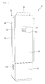
- FIG. 1 is a perspective view illustrating a configuration of an air conditioner 10 according to an embodiment
- FIG. 2 is a view illustrating a partial configuration of the air conditioner 10.
- the air conditioner 10 includes a body 20 provided with an inlet (not shown) and outlets 40 and 50 and forming an external shape.
- the air conditioner 10 may be an indoor unit installed in an indoor space and discharging the air.
- a heat exchanger and a ventilating fan may be provided in the body 20.
- the inlet may be formed on a rear of the body 20.
- the outlets 40 and 50 include a side outlet 40 allowing the air sucked through the inlet to be discharged forwards or laterally from the body 20 and a top outlet 50 allowing the air to be discharged upwardly.
- the side outlet 40 is formed on both sides of the body 20 and how much open the side outlet 40 may be controlled by a discharge vane 45.
- the discharge vane 45 may be on one side of the side outlet 40 to be pivotable.
- the top outlet 50 may be selectively open according to an operation of the air conditioner 10. In detail, when the air conditioner 10 is turned on, the top outlet 50 is transferred to project upwards from a top of the body 20. When the air conditioner 10 is turned off, the top outlet 50 is transferred downwards to be contained in the body 20.
- the body 20 includes a side panel 30 forming a lateral external shape of the air conditioner 10.
- the side panel 30 may be provided on both sides of the body 20. Also, the side panel 30 is formed with the side outlet 40.
- One side of the side outlet 40 for example, a bottom thereof may be provided with a voice collecting device 100 capable of collecting voices of a user.
- the voice collecting device 100 may be provided on a left side and a right side of the body 20.
- a front of the body 20 is provided with front panels 60 and 65.
- the front panels 60 and 65 form the front external shape of the air conditioner 10.
- the front panels 60 and 65 include a top front panel 60 and a bottom front panel 65.
- the top front panel 60 includes a display unit 61 displaying information on operations of the air conditioner 10 and an input unit 63 for inputting an operation command to the air conditioner 10.
- FIG. 3 is a view illustrating a front of a voice collecting device 100
- FIG. 4 is a view illustrating a rear of the voice collecting device 100
- FIG. 5 is an exploded perspective view illustrating the voice collecting device 100
- FIG. 6 is a view illustrating a configuration of a supporting member 150.
- the voice collecting device 100 includes a coupling unit 110 coupled with the side panel 30 to be separable and a housing 120 mounted on the coupling unit 110 and containing a microphone therein.
- the coupling unit 110 includes a mounting part 112 supporting the housing 120 and one or more panel coupling parts 115 coupled with the side panel 30.
- the mounting part 112 is formed with a coupling hole 112a coupled with the housing 120.
- the housing 120 may pass through the coupling hole 112a to be extended forwards and backwards from the mounting part 112. That is, the housing 120 may be inserted into the coupling hole 112a and then may be coupled with the mounting part 112.
- the panel coupling part 115 may be provided as a plurality thereof on one side and another side of the mounting part 112. Also, the panel coupling part 115 is formed with a penetration hole 115a coupled with a fastening member (not shown). The panel coupling part 115 may be coupled with the side panel 30 by the fastening member.
- the housing 120 may have an approximate hexahedral shape forming an inner space.
- the housing 120 includes a housing body 130 exposed outwards from the coupling unit 110 and a housing cover 140 coupled with one side of the housing body 130.
- the housing body 130 is coupled with the mounting part 112, projects from the mounting part 112, and extends to a rear side of the mounting part 112 through the coupling hole 112a.
- the housing body 130 is coupled with the housing cover 140, thereby forming an inner space 131 for shutting out noises.
- a microphone 160 may be disposed in the inner space 131.
- the housing body 130 includes a first wall 130a forming a front surface of the housing 120 and a plurality of second walls 130b extending to a rear of the first wall 130a, that is, to the inside of the side panel 30.
- a front or “a front surface” designates a direction toward the outside of the side panel 30 and "a rear” or “a rear surface” designates a direction toward the inside of the side panel 30, that is, the inside of the air conditioner 10.
- the second walls 130b form four surfaces projecting forwards from the mounting part 112, and the first wall 130a is coupled with a front formed of the four second walls 130b.
- the second walls 130b may define a depth D between the front and rear of the inner space of the housing 120.
- the second walls 130b are formed to allow a lateral length of the second wall 130b, that is, a lateral width of the housing 120 to be a width W and to allow a longitudinal length of the second wall 130b, that is, a longitudinal height of the housing 120 to be a height H.
- the width W and the height H have greater values than a lateral width and a longitudinal height of the microphone 160, respectively.
- the first wall 130a is formed with a microphone installation hole 133 installed with the microphone 160 to be exposed outwards and a first coupling hole 137 inserted with the fastening member coupled with the supporting member 150.
- the microphone installation hole 133 is understood as an opening of the housing 120 to allow voices from the outside to be transferred to the microphone 160. Also, the supporting member 150 supports the microphone 160 on the inside of the first wall 130a.
- the housing cover 140 is located on a rear side of the mounting part 120. That is, the housing cover 140 may be located not to be exposed outwards from the air conditioner 10.
- the housing cover 140 is formed with a plurality of body coupling parts 145 for allowing the housing cover 140 to be coupled with housing body 130 using fastening members 148.
- the housing cover 140 is coupled with the housing body 130, thereby allowing the inner space 131 of the housing 120 to be shielded from the outside.
- the inner space 131 is not a sealed space or a vacuum but is formed to have a size capable of insulating or shutting out noises having a certain frequency.
- a length from the housing cover 140 to the first wall 130a of the housing body 130, that is, a depth from front to rear of the housing 120 may be the depth D.
- the depth D has a greater value than a length from front to rear of the microphone 160.
- a distance from the microphone 160 to one of the plurality of second walls 130b is a distance l 1 and a distance from the microphone 160 to another of the plurality of second walls 130b is a distance l 2. Also, a distance from the microphone 160 to the housing cover 140 is a distance l 3 (refer to FIG. 7 ).
- the distances l 1 and l 2 may have greater values than a longitudinal length and a lateral length of the microphone 160, respectively.
- Values of the width W, the height H, the depth D, and the distances l 1, l 2, and l 3 may be properly selected as factors for defining the inner space 131 to effectively shut out noises occurring in the air conditioner 10, particularly, noises having a low frequency of 500 Hz or less.
- the housing 120 is provided with the microphone 160 for collecting voices occurring outside the air conditioner 10 and the supporting member 150 for stably supporting the microphone 160 on the first wall 130a.
- the supporting member 150 is formed with a supporting body 151 coupled with a rear surface of the first wall 130a of the housing body 130 and an insertion hole 153 formed to be dent in one direction from the supporting body 151. At least one part of the insertion hole 153 may be formed to be round corresponding to a shape of the microphone 160.
- the supporting member 150 is formed with a second coupling hole 155 align with the first coupling hole 137 of the first wall 130a.
- the first coupling hole 137 and the second coupling hole 155 may be coupled with each other by a fastening member (not shown).
- the second coupling hole 155 may be provided as a plurality thereof on both sides of the insertion hole 153, and the first coupling hole 137 may be provided as a plurality thereof corresponding to the number of the second coupling holes 155.
- the supporting member 150 is provided, thereby preventing a separation of the microphone 160 from the housing 120 due to vibrations occurring while operating the air conditioner 10 or preventing vibrations occurring in the microphone 160.
- FIG. 7 is a cross-sectional view illustrating a state of coupling the voice collecting device 100 with the side panel 30
- FIG. 8 is a cross-sectional view illustrating a location installed with the microphone 160
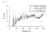
- FIG. 9 is a graph illustrating a state of reducing noises when the microphone 160 is installed in the housing 120.
- the side panel 30 includes a dent part 32 containing the housing 120.
- the dent part 32 is configured to be dent from one surface of the side panel 30 to the inside of the body 20.
- the mounting part 112 is provided inside the dent part 32, in which one side and another side of the mounting part 112 may be configured to be coupled with the dent part 32.
- the dent part 32 includes a settling part 32a allowing the housing cover 140 to be settled thereon.
- the settling part 32a forms one surface of the dent part 32.
- the microphone 160 is disposed to be closely attached to a rear of the microphone installation hole 133.
- the housing 120 includes the inner space 131 defined by sizes of the width W, the height H, and the depth D and the microphone 160 is disposed in the inner space 131 to be separate from the housing cover 140. Also, the microphone 160 is disposed to be separate from at least one part of the housing body 130.
- the microphone 160 may be separate from the second walls 130b of the housing body 130 by the distances l 1 and l 2 and may be separate from the housing cover 140 by the distance l 3.
- noises transferred from the plurality of walls 130a, 130b, and 140 forming the housing 120 may be insulated or shut out through the inner space 131, noises applied to the microphone 160 may be reduced.
- the microphone 160 is disposed to be adjacent or closely attached to an inner circumferential surface 132 of the first wall 130a. That is, the microphone 160 may be located to allow a front 161 of the microphone 160 to form the same surface together with the inner circumferential surface 132.
- voices occurring outside the air conditioner 10 may be directly transferred to the microphone 160 through the microphone installation hole 133.
- FIG. 9 is a graph illustrating the state of reducing noises when the microphone 160 is installed in the housing 120.
- FIG. 9 there is illustrated a result of experiments with respect to degrees of noises occurring when the microphone 160 is disposed in the inner space 131 of the housing 120 and when the housing 120 is not provided (a comparative example).
- respective values of the width W * the height H * the depth according to a B type may have lengths two times longer than respective values of the width W * the height H * the depth according to an A type.
- the frequency of the noise source occurring in the air conditioner 10 more includes a low frequency of about 500 Hz or less. Within a range of the corresponding frequency, greater noises occur in the comparative example. On the contrary, it may be known that noises having approximately similar volumes occur in case of the A type and the B type.
- noises of about 25 dB are applied to the microphone 160 but in cases of the A type and the B type, noises of about 15 dB are applied to the microphone 160.
- the housing 120 is provided outside the microphone 160 and the inner space 131 capable of insulating noises, that is, a noise insulation space may be provided in the housing 120, a volume of noises applied to the microphone 160 may be reduced.
- the housing 120 or the noise insulation space has a size capable of shutting out noises having a frequency within a certain range, noise insulating properties may be improved.
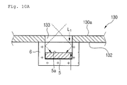
- FIG. 10A is a cross-sectional view illustrating a case of installing a microphone 5 to be separate from the opening of the housing 120
- FIG. 10B is a graph illustrating responding properties in the magnitudes of frequencies collected by a microphone between a case when the microphone is separate from the housing 120 and a case when the microphone is closely attached to the housing 120.
- the microphone 5 is disposed to be separated backwards from the microphone installation hole 133 by the a length L1.
- FIG. 10B is a graph illustrating, when voices having various frequencies (input frequencies) of a certain volume are applied from the outside of the air conditioner 120, differences in volume of voices recognized by the microphone 160.
- the certain volume is shown as "A" on the graph.
- a solid line shows responding properties in magnitude of the frequency of input voices with respect to the voice collecting device 100.
- a dotted line shows responding properties in magnitude of the frequency of input voices with respect to a voice collecting device (refer to FIG. 10A ), which is a comparative example.
- a frequency response of voices decreases. Also, considering that a frequency of voices of a human body is present within a range of from about 300 to about 3, 400 Hz, the graph shows that responding properties according to a frequency of voices may be improved by providing the voice collecting device 100.
- the microphone 160 is disposed to be closely attached to the opening of the housing 120, that is, the microphone installation hole 133, voices collected outside the air conditioner 10 may be easily transferred to the microphone 160, thereby improving a voice command recognition rate.
- a microphone is provided inside a housing and noises inside or outside the air conditioner are shut out by the housing and not applied to the microphone, thereby easily collecting desirable voices.
- a noise insulation space defined by walls separate from the microphone is provided inside the housing and has a size capable of shutting out noises having a frequency within a certain range, thereby improving noise insulating properties.
- the microphone is disposed to be closely attached to an opening of the housing, that is, the microphone installation hole, thereby improving responding properties of a voice volume according to a frequency of collected voices.
- a supporting member supporting the microphone is provided inside the housing, a deterioration of a voice collecting rate, caused by vibrations of the microphone, may be prevented.
- a recognition rate of voices collected through the microphone may be improved by shutting out noises.
- the microphone is disposed on a side of the air conditioner not to be well exposed outwards, a beautiful appearance of the air conditioner is not spoiled.
Landscapes
- Engineering & Computer Science (AREA)
- Combustion & Propulsion (AREA)
- General Engineering & Computer Science (AREA)
- Mechanical Engineering (AREA)
- Chemical & Material Sciences (AREA)
- Signal Processing (AREA)
- Physics & Mathematics (AREA)
- Acoustics & Sound (AREA)
- Human Computer Interaction (AREA)
- Details Of Audible-Bandwidth Transducers (AREA)
- Telephone Set Structure (AREA)
- Air Filters, Heat-Exchange Apparatuses, And Housings Of Air-Conditioning Units (AREA)
- Soundproofing, Sound Blocking, And Sound Damping (AREA)
Applications Claiming Priority (1)
| Application Number | Priority Date | Filing Date | Title |
|---|---|---|---|
| KR1020130056407A KR102087692B1 (ko) | 2013-05-20 | 2013-05-20 | 공기 조화기 |
Publications (3)
| Publication Number | Publication Date |
|---|---|
| EP2806224A2 true EP2806224A2 (de) | 2014-11-26 |
| EP2806224A3 EP2806224A3 (de) | 2014-12-17 |
| EP2806224B1 EP2806224B1 (de) | 2018-01-10 |
Family
ID=50731997
Family Applications (1)
| Application Number | Title | Priority Date | Filing Date |
|---|---|---|---|
| EP14168844.0A Not-in-force EP2806224B1 (de) | 2013-05-20 | 2014-05-19 | Klimaanlage |
Country Status (4)
| Country | Link |
|---|---|
| US (1) | US9510073B2 (de) |
| EP (1) | EP2806224B1 (de) |
| KR (1) | KR102087692B1 (de) |
| CN (1) | CN104180438B (de) |
Families Citing this family (13)
| Publication number | Priority date | Publication date | Assignee | Title |
|---|---|---|---|---|
| CN104505092B (zh) * | 2014-12-10 | 2017-12-22 | 广东美的制冷设备有限公司 | 空调器语音控制方法和系统 |
| CN106152454A (zh) * | 2016-08-08 | 2016-11-23 | 珠海格力电器股份有限公司 | 一种装饰条、空调器及装饰条的装配方法 |
| KR102399913B1 (ko) * | 2017-07-24 | 2022-05-18 | 엘지전자 주식회사 | 공기조화기 |
| KR102179566B1 (ko) | 2018-10-01 | 2020-11-17 | 엘지전자 주식회사 | 음성인식 장치를 구비하는 공기 조화기 |
| KR102210146B1 (ko) | 2018-10-01 | 2021-02-01 | 엘지전자 주식회사 | 음성인식 장치를 구비하는 가전제품 |
| KR102246903B1 (ko) * | 2019-01-08 | 2021-04-29 | 엘지전자 주식회사 | 가습청정장치 |
| KR102486865B1 (ko) * | 2019-01-08 | 2023-01-09 | 엘지전자 주식회사 | 가습청정장치 |
| CN111426050B (zh) * | 2019-01-09 | 2021-11-30 | 青岛海尔空调器有限总公司 | 一种空调及其控制方法 |
| US11114102B2 (en) | 2019-01-16 | 2021-09-07 | Lg Electronics Inc. | Appliance including voice recognition device |
| KR102729082B1 (ko) * | 2019-03-05 | 2024-11-14 | 삼성전자주식회사 | 공기조화기 |
| CN110793101B (zh) * | 2019-12-04 | 2025-05-13 | 宁波奥克斯电气有限公司 | 一种麦克风组件与空调的安装结构及空调器 |
| KR102372538B1 (ko) * | 2019-12-16 | 2022-03-10 | 엘지전자 주식회사 | 정수기 |
| KR102800259B1 (ko) * | 2020-05-26 | 2025-04-23 | 엘지전자 주식회사 | 가습청정장치 |
Family Cites Families (16)
| Publication number | Priority date | Publication date | Assignee | Title |
|---|---|---|---|---|
| JPS57175416A (en) | 1981-04-20 | 1982-10-28 | Toyota Motor Corp | Controller for air conditioner |
| US5010739A (en) * | 1989-06-30 | 1991-04-30 | Kabushiki Kaisha Toshiba | Air conditioning apparatus having audible sound level control function |
| KR100471455B1 (ko) * | 2003-03-22 | 2005-03-09 | 엘지전자 주식회사 | 공기조화기의 리모콘 보관함 및 리모콘 보관 식별 장치 |
| JP2005037447A (ja) * | 2003-07-15 | 2005-02-10 | Matsushita Electric Ind Co Ltd | 空気調和機の騒音制御装置 |
| KR20060097455A (ko) * | 2005-03-09 | 2006-09-14 | 엘지전자 주식회사 | 음성인식기능이 구비된 멜로디 공기조화기 |
| KR20080055464A (ko) * | 2006-12-15 | 2008-06-19 | 엘지전자 주식회사 | 공기조화기 |
| JP4858252B2 (ja) * | 2007-03-20 | 2012-01-18 | パナソニック株式会社 | 空気調和機の遠隔制御装置 |
| KR200467930Y1 (ko) * | 2008-06-18 | 2013-07-11 | 삼성전자주식회사 | 공기조화기 |
| JP5481852B2 (ja) * | 2008-12-12 | 2014-04-23 | 船井電機株式会社 | マイクロホンユニット及びそれを備えた音声入力装置 |
| KR101598626B1 (ko) * | 2009-01-09 | 2016-02-29 | 엘지전자 주식회사 | 공기 조화기 실내기 |
| WO2010095203A1 (ja) * | 2009-02-17 | 2010-08-26 | 株式会社 村田製作所 | 音響的トランスデューサユニット |
| CN101881484B (zh) * | 2009-05-05 | 2012-09-26 | 海尔集团公司 | 一种声控空调器 |
| WO2011029401A1 (zh) | 2009-09-11 | 2011-03-17 | 珠海格力电器股份有限公司 | 盲人用空调系统和盲人用遥控器 |
| JP6061441B2 (ja) | 2010-11-24 | 2017-01-18 | ジョンソンコントロールズ ヒタチ エア コンディショニング テクノロジー(ホンコン)リミテッド | 空気調和機 |
| JP5799619B2 (ja) | 2011-06-24 | 2015-10-28 | 船井電機株式会社 | マイクロホンユニット |
| CN202747547U (zh) * | 2012-09-07 | 2013-02-20 | 海尔集团公司 | 可语音控制的空调以及包括该空调的系统 |
-
2013
- 2013-05-20 KR KR1020130056407A patent/KR102087692B1/ko active Active
-
2014
- 2014-05-16 US US14/279,916 patent/US9510073B2/en active Active
- 2014-05-19 EP EP14168844.0A patent/EP2806224B1/de not_active Not-in-force
- 2014-05-20 CN CN201410214256.2A patent/CN104180438B/zh not_active Expired - Fee Related
Non-Patent Citations (1)
| Title |
|---|
| None |
Also Published As
| Publication number | Publication date |
|---|---|
| KR20140136199A (ko) | 2014-11-28 |
| EP2806224B1 (de) | 2018-01-10 |
| CN104180438A (zh) | 2014-12-03 |
| CN104180438B (zh) | 2018-05-25 |
| KR102087692B1 (ko) | 2020-03-11 |
| US20140341414A1 (en) | 2014-11-20 |
| EP2806224A3 (de) | 2014-12-17 |
| US9510073B2 (en) | 2016-11-29 |
Similar Documents
| Publication | Publication Date | Title |
|---|---|---|
| EP2806224B1 (de) | Klimaanlage | |
| EP3040630B1 (de) | Aussenvorrichtung einer klimaanlage | |
| CN106196332B (zh) | 空调机的室外机 | |
| CN205174613U (zh) | 室外机 | |
| JP6299552B2 (ja) | 天井埋込型空気調和機 | |
| EP3040631A1 (de) | Aussenvorrichtung einer klimaanlage | |
| WO2004042287A1 (ja) | 冷凍装置の室外ユニット、及び室外ユニットの電装品箱 | |
| US4465499A (en) | Assembly for securing filter channels to support structure in a casing such as the housing of an air handling unit and for selectively providing flanges for securing a duct to the casing | |
| JP2016121864A (ja) | 空気調和機の室外機 | |
| CN112888903B (zh) | 空调室内机的组装结构 | |
| KR101734722B1 (ko) | 공기 조화기의 오리피스 | |
| EP2180265A3 (de) | Außenraumeinheit für Klimaanlage | |
| JP6139669B2 (ja) | 空気調和機 | |
| CN204612007U (zh) | 空调机的室外机 | |
| KR101727413B1 (ko) | 공기 조화기의 에어가이드 | |
| KR100575312B1 (ko) | 공기 조화기의 실내기 | |
| JP2014240713A (ja) | 空気調和装置の室外ユニット | |
| JPH1194294A (ja) | 天吊型空気調和装置 | |
| KR20070075614A (ko) | 공기조화기의 진동방지구조 | |
| KR100652805B1 (ko) | 공기조화기의 실외기의 설치구조 | |
| CN204313394U (zh) | 兼有换气功能的吸顶嵌入式空调 | |
| JP2013221687A (ja) | 空気調和機 | |
| KR102408367B1 (ko) | 공기 조화기 | |
| CN223829564U (zh) | 电控盒及厨房空调 | |
| KR100500988B1 (ko) | 공기조화기 |
Legal Events
| Date | Code | Title | Description |
|---|---|---|---|
| PUAL | Search report despatched |
Free format text: ORIGINAL CODE: 0009013 |
|
| PUAI | Public reference made under article 153(3) epc to a published international application that has entered the european phase |
Free format text: ORIGINAL CODE: 0009012 |
|
| 17P | Request for examination filed |
Effective date: 20140618 |
|
| AK | Designated contracting states |
Kind code of ref document: A2 Designated state(s): AL AT BE BG CH CY CZ DE DK EE ES FI FR GB GR HR HU IE IS IT LI LT LU LV MC MK MT NL NO PL PT RO RS SE SI SK SM TR |
|
| AX | Request for extension of the european patent |
Extension state: BA ME |
|
| AK | Designated contracting states |
Kind code of ref document: A3 Designated state(s): AL AT BE BG CH CY CZ DE DK EE ES FI FR GB GR HR HU IE IS IT LI LT LU LV MC MK MT NL NO PL PT RO RS SE SI SK SM TR |
|
| AX | Request for extension of the european patent |
Extension state: BA ME |
|
| RIC1 | Information provided on ipc code assigned before grant |
Ipc: F24F 11/00 20060101AFI20141110BHEP Ipc: F24F 13/20 20060101ALI20141110BHEP Ipc: F24F 13/24 20060101ALI20141110BHEP |
|
| RAP1 | Party data changed (applicant data changed or rights of an application transferred) |
Owner name: LG ELECTRONICS INC. |
|
| RBV | Designated contracting states (corrected) |
Designated state(s): AL AT BE BG CH CY CZ DE DK EE ES FI FR GB GR HR HU IE IS IT LI LT LU LV MC MK MT NL NO PL PT RO RS SE SI SK SM TR |
|
| GRAP | Despatch of communication of intention to grant a patent |
Free format text: ORIGINAL CODE: EPIDOSNIGR1 |
|
| INTG | Intention to grant announced |
Effective date: 20170707 |
|
| GRAS | Grant fee paid |
Free format text: ORIGINAL CODE: EPIDOSNIGR3 |
|
| GRAJ | Information related to disapproval of communication of intention to grant by the applicant or resumption of examination proceedings by the epo deleted |
Free format text: ORIGINAL CODE: EPIDOSDIGR1 |
|
| GRAL | Information related to payment of fee for publishing/printing deleted |
Free format text: ORIGINAL CODE: EPIDOSDIGR3 |
|
| GRAR | Information related to intention to grant a patent recorded |
Free format text: ORIGINAL CODE: EPIDOSNIGR71 |
|
| GRAA | (expected) grant |
Free format text: ORIGINAL CODE: 0009210 |
|
| INTC | Intention to grant announced (deleted) | ||
| AK | Designated contracting states |
Kind code of ref document: B1 Designated state(s): AL AT BE BG CH CY CZ DE DK EE ES FI FR GB GR HR HU IE IS IT LI LT LU LV MC MK MT NL NO PL PT RO RS SE SI SK SM TR |
|
| INTG | Intention to grant announced |
Effective date: 20171204 |
|
| REG | Reference to a national code |
Ref country code: CH Ref legal event code: EP Ref country code: AT Ref legal event code: REF Ref document number: 962818 Country of ref document: AT Kind code of ref document: T Effective date: 20180115 |
|
| REG | Reference to a national code |
Ref country code: IE Ref legal event code: FG4D |
|
| REG | Reference to a national code |
Ref country code: DE Ref legal event code: R096 Ref document number: 602014019603 Country of ref document: DE |
|
| REG | Reference to a national code |
Ref country code: NL Ref legal event code: MP Effective date: 20180110 |
|
| REG | Reference to a national code |
Ref country code: AT Ref legal event code: MK05 Ref document number: 962818 Country of ref document: AT Kind code of ref document: T Effective date: 20180110 |
|
| PG25 | Lapsed in a contracting state [announced via postgrant information from national office to epo] |
Ref country code: NL Free format text: LAPSE BECAUSE OF FAILURE TO SUBMIT A TRANSLATION OF THE DESCRIPTION OR TO PAY THE FEE WITHIN THE PRESCRIBED TIME-LIMIT Effective date: 20180110 |
|
| PG25 | Lapsed in a contracting state [announced via postgrant information from national office to epo] |
Ref country code: CY Free format text: LAPSE BECAUSE OF FAILURE TO SUBMIT A TRANSLATION OF THE DESCRIPTION OR TO PAY THE FEE WITHIN THE PRESCRIBED TIME-LIMIT Effective date: 20180110 Ref country code: HR Free format text: LAPSE BECAUSE OF FAILURE TO SUBMIT A TRANSLATION OF THE DESCRIPTION OR TO PAY THE FEE WITHIN THE PRESCRIBED TIME-LIMIT Effective date: 20180110 Ref country code: ES Free format text: LAPSE BECAUSE OF FAILURE TO SUBMIT A TRANSLATION OF THE DESCRIPTION OR TO PAY THE FEE WITHIN THE PRESCRIBED TIME-LIMIT Effective date: 20180110 Ref country code: LT Free format text: LAPSE BECAUSE OF FAILURE TO SUBMIT A TRANSLATION OF THE DESCRIPTION OR TO PAY THE FEE WITHIN THE PRESCRIBED TIME-LIMIT Effective date: 20180110 Ref country code: NO Free format text: LAPSE BECAUSE OF FAILURE TO SUBMIT A TRANSLATION OF THE DESCRIPTION OR TO PAY THE FEE WITHIN THE PRESCRIBED TIME-LIMIT Effective date: 20180410 Ref country code: FI Free format text: LAPSE BECAUSE OF FAILURE TO SUBMIT A TRANSLATION OF THE DESCRIPTION OR TO PAY THE FEE WITHIN THE PRESCRIBED TIME-LIMIT Effective date: 20180110 |
|
| PG25 | Lapsed in a contracting state [announced via postgrant information from national office to epo] |
Ref country code: LV Free format text: LAPSE BECAUSE OF FAILURE TO SUBMIT A TRANSLATION OF THE DESCRIPTION OR TO PAY THE FEE WITHIN THE PRESCRIBED TIME-LIMIT Effective date: 20180110 Ref country code: SE Free format text: LAPSE BECAUSE OF FAILURE TO SUBMIT A TRANSLATION OF THE DESCRIPTION OR TO PAY THE FEE WITHIN THE PRESCRIBED TIME-LIMIT Effective date: 20180110 Ref country code: AT Free format text: LAPSE BECAUSE OF FAILURE TO SUBMIT A TRANSLATION OF THE DESCRIPTION OR TO PAY THE FEE WITHIN THE PRESCRIBED TIME-LIMIT Effective date: 20180110 Ref country code: PL Free format text: LAPSE BECAUSE OF FAILURE TO SUBMIT A TRANSLATION OF THE DESCRIPTION OR TO PAY THE FEE WITHIN THE PRESCRIBED TIME-LIMIT Effective date: 20180110 Ref country code: BG Free format text: LAPSE BECAUSE OF FAILURE TO SUBMIT A TRANSLATION OF THE DESCRIPTION OR TO PAY THE FEE WITHIN THE PRESCRIBED TIME-LIMIT Effective date: 20180410 Ref country code: IS Free format text: LAPSE BECAUSE OF FAILURE TO SUBMIT A TRANSLATION OF THE DESCRIPTION OR TO PAY THE FEE WITHIN THE PRESCRIBED TIME-LIMIT Effective date: 20180510 Ref country code: GR Free format text: LAPSE BECAUSE OF FAILURE TO SUBMIT A TRANSLATION OF THE DESCRIPTION OR TO PAY THE FEE WITHIN THE PRESCRIBED TIME-LIMIT Effective date: 20180411 Ref country code: RS Free format text: LAPSE BECAUSE OF FAILURE TO SUBMIT A TRANSLATION OF THE DESCRIPTION OR TO PAY THE FEE WITHIN THE PRESCRIBED TIME-LIMIT Effective date: 20180110 |
|
| REG | Reference to a national code |
Ref country code: DE Ref legal event code: R097 Ref document number: 602014019603 Country of ref document: DE |
|
| PG25 | Lapsed in a contracting state [announced via postgrant information from national office to epo] |
Ref country code: AL Free format text: LAPSE BECAUSE OF FAILURE TO SUBMIT A TRANSLATION OF THE DESCRIPTION OR TO PAY THE FEE WITHIN THE PRESCRIBED TIME-LIMIT Effective date: 20180110 Ref country code: IT Free format text: LAPSE BECAUSE OF FAILURE TO SUBMIT A TRANSLATION OF THE DESCRIPTION OR TO PAY THE FEE WITHIN THE PRESCRIBED TIME-LIMIT Effective date: 20180110 Ref country code: RO Free format text: LAPSE BECAUSE OF FAILURE TO SUBMIT A TRANSLATION OF THE DESCRIPTION OR TO PAY THE FEE WITHIN THE PRESCRIBED TIME-LIMIT Effective date: 20180110 Ref country code: EE Free format text: LAPSE BECAUSE OF FAILURE TO SUBMIT A TRANSLATION OF THE DESCRIPTION OR TO PAY THE FEE WITHIN THE PRESCRIBED TIME-LIMIT Effective date: 20180110 |
|
| PLBE | No opposition filed within time limit |
Free format text: ORIGINAL CODE: 0009261 |
|
| STAA | Information on the status of an ep patent application or granted ep patent |
Free format text: STATUS: NO OPPOSITION FILED WITHIN TIME LIMIT |
|
| PG25 | Lapsed in a contracting state [announced via postgrant information from national office to epo] |
Ref country code: SM Free format text: LAPSE BECAUSE OF FAILURE TO SUBMIT A TRANSLATION OF THE DESCRIPTION OR TO PAY THE FEE WITHIN THE PRESCRIBED TIME-LIMIT Effective date: 20180110 Ref country code: CZ Free format text: LAPSE BECAUSE OF FAILURE TO SUBMIT A TRANSLATION OF THE DESCRIPTION OR TO PAY THE FEE WITHIN THE PRESCRIBED TIME-LIMIT Effective date: 20180110 Ref country code: DK Free format text: LAPSE BECAUSE OF FAILURE TO SUBMIT A TRANSLATION OF THE DESCRIPTION OR TO PAY THE FEE WITHIN THE PRESCRIBED TIME-LIMIT Effective date: 20180110 Ref country code: SK Free format text: LAPSE BECAUSE OF FAILURE TO SUBMIT A TRANSLATION OF THE DESCRIPTION OR TO PAY THE FEE WITHIN THE PRESCRIBED TIME-LIMIT Effective date: 20180110 |
|
| REG | Reference to a national code |
Ref country code: CH Ref legal event code: PL |
|
| 26N | No opposition filed |
Effective date: 20181011 |
|
| GBPC | Gb: european patent ceased through non-payment of renewal fee |
Effective date: 20180519 |
|
| REG | Reference to a national code |
Ref country code: BE Ref legal event code: MM Effective date: 20180531 |
|
| PG25 | Lapsed in a contracting state [announced via postgrant information from national office to epo] |
Ref country code: MC Free format text: LAPSE BECAUSE OF FAILURE TO SUBMIT A TRANSLATION OF THE DESCRIPTION OR TO PAY THE FEE WITHIN THE PRESCRIBED TIME-LIMIT Effective date: 20180110 |
|
| REG | Reference to a national code |
Ref country code: IE Ref legal event code: MM4A |
|
| PG25 | Lapsed in a contracting state [announced via postgrant information from national office to epo] |
Ref country code: CH Free format text: LAPSE BECAUSE OF NON-PAYMENT OF DUE FEES Effective date: 20180531 Ref country code: LI Free format text: LAPSE BECAUSE OF NON-PAYMENT OF DUE FEES Effective date: 20180531 Ref country code: SI Free format text: LAPSE BECAUSE OF FAILURE TO SUBMIT A TRANSLATION OF THE DESCRIPTION OR TO PAY THE FEE WITHIN THE PRESCRIBED TIME-LIMIT Effective date: 20180110 |
|
| PG25 | Lapsed in a contracting state [announced via postgrant information from national office to epo] |
Ref country code: LU Free format text: LAPSE BECAUSE OF NON-PAYMENT OF DUE FEES Effective date: 20180519 |
|
| PG25 | Lapsed in a contracting state [announced via postgrant information from national office to epo] |
Ref country code: FR Free format text: LAPSE BECAUSE OF NON-PAYMENT OF DUE FEES Effective date: 20180531 Ref country code: IE Free format text: LAPSE BECAUSE OF NON-PAYMENT OF DUE FEES Effective date: 20180519 Ref country code: GB Free format text: LAPSE BECAUSE OF NON-PAYMENT OF DUE FEES Effective date: 20180519 |
|
| PG25 | Lapsed in a contracting state [announced via postgrant information from national office to epo] |
Ref country code: BE Free format text: LAPSE BECAUSE OF NON-PAYMENT OF DUE FEES Effective date: 20180531 |
|
| PG25 | Lapsed in a contracting state [announced via postgrant information from national office to epo] |
Ref country code: MT Free format text: LAPSE BECAUSE OF NON-PAYMENT OF DUE FEES Effective date: 20180519 |
|
| PG25 | Lapsed in a contracting state [announced via postgrant information from national office to epo] |
Ref country code: TR Free format text: LAPSE BECAUSE OF FAILURE TO SUBMIT A TRANSLATION OF THE DESCRIPTION OR TO PAY THE FEE WITHIN THE PRESCRIBED TIME-LIMIT Effective date: 20180110 |
|
| PG25 | Lapsed in a contracting state [announced via postgrant information from national office to epo] |
Ref country code: PT Free format text: LAPSE BECAUSE OF FAILURE TO SUBMIT A TRANSLATION OF THE DESCRIPTION OR TO PAY THE FEE WITHIN THE PRESCRIBED TIME-LIMIT Effective date: 20180110 Ref country code: HU Free format text: LAPSE BECAUSE OF FAILURE TO SUBMIT A TRANSLATION OF THE DESCRIPTION OR TO PAY THE FEE WITHIN THE PRESCRIBED TIME-LIMIT; INVALID AB INITIO Effective date: 20140519 |
|
| PG25 | Lapsed in a contracting state [announced via postgrant information from national office to epo] |
Ref country code: MK Free format text: LAPSE BECAUSE OF NON-PAYMENT OF DUE FEES Effective date: 20180110 |
|
| PGFP | Annual fee paid to national office [announced via postgrant information from national office to epo] |
Ref country code: DE Payment date: 20220405 Year of fee payment: 9 |
|
| REG | Reference to a national code |
Ref country code: DE Ref legal event code: R119 Ref document number: 602014019603 Country of ref document: DE |
|
| PG25 | Lapsed in a contracting state [announced via postgrant information from national office to epo] |
Ref country code: DE Free format text: LAPSE BECAUSE OF NON-PAYMENT OF DUE FEES Effective date: 20231201 |