EP2806237A1 - Procédé de refroidissement d'un système de réfrigération et réfrigérateur - Google Patents
Procédé de refroidissement d'un système de réfrigération et réfrigérateur Download PDFInfo
- Publication number
- EP2806237A1 EP2806237A1 EP14168911.7A EP14168911A EP2806237A1 EP 2806237 A1 EP2806237 A1 EP 2806237A1 EP 14168911 A EP14168911 A EP 14168911A EP 2806237 A1 EP2806237 A1 EP 2806237A1
- Authority
- EP
- European Patent Office
- Prior art keywords
- cavity
- temperature
- fan
- evaporator
- compressor
- Prior art date
- Legal status (The legal status is an assumption and is not a legal conclusion. Google has not performed a legal analysis and makes no representation as to the accuracy of the status listed.)
- Granted
Links
Images


Classifications
-
- F—MECHANICAL ENGINEERING; LIGHTING; HEATING; WEAPONS; BLASTING
- F25—REFRIGERATION OR COOLING; COMBINED HEATING AND REFRIGERATION SYSTEMS; HEAT PUMP SYSTEMS; MANUFACTURE OR STORAGE OF ICE; LIQUEFACTION SOLIDIFICATION OF GASES
- F25D—REFRIGERATORS; COLD ROOMS; ICE-BOXES; COOLING OR FREEZING APPARATUS NOT OTHERWISE PROVIDED FOR
- F25D11/00—Self-contained movable devices, e.g. domestic refrigerators
- F25D11/02—Self-contained movable devices, e.g. domestic refrigerators with cooling compartments at different temperatures
- F25D11/022—Self-contained movable devices, e.g. domestic refrigerators with cooling compartments at different temperatures with two or more evaporators
-
- F—MECHANICAL ENGINEERING; LIGHTING; HEATING; WEAPONS; BLASTING
- F25—REFRIGERATION OR COOLING; COMBINED HEATING AND REFRIGERATION SYSTEMS; HEAT PUMP SYSTEMS; MANUFACTURE OR STORAGE OF ICE; LIQUEFACTION SOLIDIFICATION OF GASES
- F25D—REFRIGERATORS; COLD ROOMS; ICE-BOXES; COOLING OR FREEZING APPARATUS NOT OTHERWISE PROVIDED FOR
- F25D17/00—Arrangements for circulating cooling fluids; Arrangements for circulating gas, e.g. air, within refrigerated spaces
- F25D17/04—Arrangements for circulating cooling fluids; Arrangements for circulating gas, e.g. air, within refrigerated spaces for circulating air, e.g. by convection
- F25D17/06—Arrangements for circulating cooling fluids; Arrangements for circulating gas, e.g. air, within refrigerated spaces for circulating air, e.g. by convection by forced circulation
- F25D17/062—Arrangements for circulating cooling fluids; Arrangements for circulating gas, e.g. air, within refrigerated spaces for circulating air, e.g. by convection by forced circulation in household refrigerators
- F25D17/065—Arrangements for circulating cooling fluids; Arrangements for circulating gas, e.g. air, within refrigerated spaces for circulating air, e.g. by convection by forced circulation in household refrigerators with compartments at different temperatures
-
- F—MECHANICAL ENGINEERING; LIGHTING; HEATING; WEAPONS; BLASTING
- F25—REFRIGERATION OR COOLING; COMBINED HEATING AND REFRIGERATION SYSTEMS; HEAT PUMP SYSTEMS; MANUFACTURE OR STORAGE OF ICE; LIQUEFACTION SOLIDIFICATION OF GASES
- F25D—REFRIGERATORS; COLD ROOMS; ICE-BOXES; COOLING OR FREEZING APPARATUS NOT OTHERWISE PROVIDED FOR
- F25D29/00—Arrangement or mounting of control or safety devices
-
- F—MECHANICAL ENGINEERING; LIGHTING; HEATING; WEAPONS; BLASTING
- F25—REFRIGERATION OR COOLING; COMBINED HEATING AND REFRIGERATION SYSTEMS; HEAT PUMP SYSTEMS; MANUFACTURE OR STORAGE OF ICE; LIQUEFACTION SOLIDIFICATION OF GASES
- F25B—REFRIGERATION MACHINES, PLANTS OR SYSTEMS; COMBINED HEATING AND REFRIGERATION SYSTEMS; HEAT PUMP SYSTEMS
- F25B2600/00—Control issues
- F25B2600/02—Compressor control
- F25B2600/025—Compressor control by controlling speed
- F25B2600/0251—Compressor control by controlling speed with on-off operation
-
- F—MECHANICAL ENGINEERING; LIGHTING; HEATING; WEAPONS; BLASTING
- F25—REFRIGERATION OR COOLING; COMBINED HEATING AND REFRIGERATION SYSTEMS; HEAT PUMP SYSTEMS; MANUFACTURE OR STORAGE OF ICE; LIQUEFACTION SOLIDIFICATION OF GASES
- F25D—REFRIGERATORS; COLD ROOMS; ICE-BOXES; COOLING OR FREEZING APPARATUS NOT OTHERWISE PROVIDED FOR
- F25D2600/00—Control issues
- F25D2600/06—Controlling according to a predetermined profile
-
- F—MECHANICAL ENGINEERING; LIGHTING; HEATING; WEAPONS; BLASTING
- F25—REFRIGERATION OR COOLING; COMBINED HEATING AND REFRIGERATION SYSTEMS; HEAT PUMP SYSTEMS; MANUFACTURE OR STORAGE OF ICE; LIQUEFACTION SOLIDIFICATION OF GASES
- F25D—REFRIGERATORS; COLD ROOMS; ICE-BOXES; COOLING OR FREEZING APPARATUS NOT OTHERWISE PROVIDED FOR
- F25D2700/00—Means for sensing or measuring; Sensors therefor
- F25D2700/10—Sensors measuring the temperature of the evaporator
-
- F—MECHANICAL ENGINEERING; LIGHTING; HEATING; WEAPONS; BLASTING
- F25—REFRIGERATION OR COOLING; COMBINED HEATING AND REFRIGERATION SYSTEMS; HEAT PUMP SYSTEMS; MANUFACTURE OR STORAGE OF ICE; LIQUEFACTION SOLIDIFICATION OF GASES
- F25D—REFRIGERATORS; COLD ROOMS; ICE-BOXES; COOLING OR FREEZING APPARATUS NOT OTHERWISE PROVIDED FOR
- F25D2700/00—Means for sensing or measuring; Sensors therefor
- F25D2700/12—Sensors measuring the inside temperature
- F25D2700/122—Sensors measuring the inside temperature of freezer compartments
-
- F—MECHANICAL ENGINEERING; LIGHTING; HEATING; WEAPONS; BLASTING
- F25—REFRIGERATION OR COOLING; COMBINED HEATING AND REFRIGERATION SYSTEMS; HEAT PUMP SYSTEMS; MANUFACTURE OR STORAGE OF ICE; LIQUEFACTION SOLIDIFICATION OF GASES
- F25D—REFRIGERATORS; COLD ROOMS; ICE-BOXES; COOLING OR FREEZING APPARATUS NOT OTHERWISE PROVIDED FOR
- F25D2700/00—Means for sensing or measuring; Sensors therefor
- F25D2700/12—Sensors measuring the inside temperature
- F25D2700/123—Sensors measuring the inside temperature more than one sensor measuring the inside temperature in a compartment
-
- Y—GENERAL TAGGING OF NEW TECHNOLOGICAL DEVELOPMENTS; GENERAL TAGGING OF CROSS-SECTIONAL TECHNOLOGIES SPANNING OVER SEVERAL SECTIONS OF THE IPC; TECHNICAL SUBJECTS COVERED BY FORMER USPC CROSS-REFERENCE ART COLLECTIONS [XRACs] AND DIGESTS
- Y02—TECHNOLOGIES OR APPLICATIONS FOR MITIGATION OR ADAPTATION AGAINST CLIMATE CHANGE
- Y02B—CLIMATE CHANGE MITIGATION TECHNOLOGIES RELATED TO BUILDINGS, e.g. HOUSING, HOUSE APPLIANCES OR RELATED END-USER APPLICATIONS
- Y02B40/00—Technologies aiming at improving the efficiency of home appliances, e.g. induction cooking or efficient technologies for refrigerators, freezers or dish washers
Definitions
- the present invention relates to a method for the operation of a refrigerated system, in particular a "combined” or “double-door” domestic refrigerator, in which the consumption of energy to cool and preserve the items contained within it, foods in particular, is optimised.
- this invention relates to a refrigerated system provided with at least two cavities or compartments and equipped with a refrigerating circuit powered by a compressor.
- a refrigerating circuit powered by a compressor.
- each of the two cavities is at least one evaporator.
- the evaporators are arranged to cool the first cavity, typically a freezer compartment, to a lower temperature than that of the second cavity.
- the refrigerated system also comprises a solenoid valve capable of connecting the compressor of the refrigerated system to the first evaporator located in the first cavity, according to a first mode defined as single connection of the compressor to the first evaporator, and to connect the compressor to the first evaporator and to at least a second evaporator located in the second cavity, in a second mode defined as multiple connection of the compressor to the evaporators.
- a control system supervises and activates the operations of the system.
- the multiple connection mode is of the type with the first and second evaporator connected in series to the compressor and where the solenoid valve is preferably a two- or multi-way valve.
- the solenoid valve is capable of bypassing the second evaporator when the first evaporator and second evaporator are connected in series.
- Additional evaporators may be present, located in one or more cavities or in additional cavities, connected together in the multiple connection mode by means of one or more solenoid valves. Note that in the mode of multiple connection of the compressor to the evaporators, according to the invention the latter may be connected together, apart from in series, also in parallel or in a mixed connection mode.
- the method according to the present invention can also be applied both to refrigerated systems equipped with ON/OFF type compressors and to those equipped with variable-speed compressors.
- At least the first cavity is equipped with a fan to circulate the cold air in the first compartment and with one or more temperature probes or sensors for the thermostatic control of the compartment.
- the temperature sensor can be arranged in the internal space of the compartment and/or directly on the evaporator.
- the present method can also be applied both to refrigerated systems equipped with an hysteresis-type control logic to regulate the temperature of the compressor (typically, but not exclusively used in combination with ON/OFF compressors), and to systems that regulate the temperature by applying a PID-type control logic (typically by regulating the frequency of a variable-speed compressor). Note that the present method can also be applied with other more sophisticated automatic temperature control methods than those mentioned above.
- Refrigeration systems of the type described above are known wherein cooling of the cell (or cavity) to a lower temperature, typically a freezer cell, is achieved by operating the evaporator together with a fan located in the same cavity during the single and multiple connection mode, until a useful lower temperature threshold is reached, at which the cooling of the cell is interrupted. These systems often waste energy since this energy is not always efficiently used to cool the elements located in the first compartment.
- the aim of this invention is to provide a method that enables the energy consumption of the entire system to be reduced, while continuing to guarantee the cooling of the cell cooled to a lower temperature. This aim is achieved by the method described in the present invention in accordance with the characteristics of claim 1.
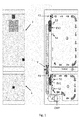
- Figure 1 describes, by way of a non-limiting example, a refrigerated system to which the method of the present invention is applied.
- This is a "combined" refrigerator that comprises a first cavity 1 and a second cavity 2.
- the first cavity 1 is cooled in order to freeze items, particularly foods, to a first average reference temperature TSET1, for example -18°C.
- the second cavity 2 is of a refrigerator type for preserving fresh foods and is cooled to a second average reference temperature TSET2, for example 5°C.
- the freezer compartment is a first temperature probe S1, a sensor used to control the temperature in the first cavity 1.
- the refrigerated system comprises at least two evaporators EV1, EV2. In each cavity there is at least one evaporator.
- the system in Figure 1 shows a first evaporator EV1 located in the first cavity 1 and a second evaporator EV2 located in the second cavity 2.
- a solenoid valve V enables the connection of the ON/OFF compressor CMP of the refrigerated system to one or more evaporators.
- the solenoid valve V is a two-state valve (known also as a two-way valve). In a first state, it enables the connection (single, exclusive) of the compressor CMP to the first evaporator EV1 located in the first cavity 1. In this single connection mode only the first cavity 1 is cooled by means of the first evaporator EV1.
- the solenoid valve V connects the compressor CMP to the first evaporator EV1 connected in series to the second evaporator EV2.
- the first 1 and second 2 cavity are cooled at the same time by means of the first evaporator EV1 and the second evaporator EV2 respectively.
- a second temperature sensor/probe S2 may be present in the first cavity 1, located near or directly upon the evaporator EV1.
- a first air circulation fan F1 is located in the first cavity 1 in order to create a uniform temperature inside said cavity 1.
- a second optional fan F2 is located in the second cavity 2, as illustrated in Fig. 1 .
- the first freezer cavity 1 a standard load, of a regulatory type, is placed, which better enables the advantages of the method according to this invention compared to the prior art to be assessed when energy consumption tests according to existing law are performed, the graphs of which, described below for the purposes of the present invention, represent an extract.
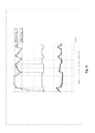
- Figure 2 firstly shows, as a comparison, the graph of a test according to a non-optimised cooling method currently in use on commercial products, according to the prior art.
- the graph shows the behaviour of the temperature T1 of the first cavity 1 or freezer cell, recorded by the first temperature probe/sensor S 1.
- the graph also shows the SCMP state of the ON/OFF compressor CMP which is represented as being ON, when the level of the "SCMP" signal in the graph is high, or OFF, when the level of the "SCMP" signal in the graph is low.
- the graph also shows the SV operating state of the solenoid valve V which corresponds to a single connection mode of the compressor to the first evaporator EV1 in relation to a high level of the "SV" signal shown, and to a multiple connection mode of the compressor to the evaporators, to a low level of the "SV” signal.
- the graph shows the operating state SF1 of the first fan F1, which is on when there is a non-zero "SF1" pilot signal and off in the opposite case (low “SF1" signal level).
- the graph shows that when the SCMP state of the compressor CMP and the SF1 status of the first fan F1 located in the first cavity 1 are both on during the single connection mode of the first evaporator EV1 to the compressor CMP, the average gradient P1 of the temperature signal T1 is negative.
- the method according to the invention involves performing the following steps:
- the first step consists in cooling the first cavity/compartment 1 to a temperature T1 below that of the second cavity 2, in a first mode in which the first evaporator EV1 is connected to the compressor CMP cutting off the supply to the second evaporator EV2, and switching on the first fan F1 located in the first cavity 1.
- the second step consists in switching the state of the solenoid valve V in the second multiple connection mode of the compressor CMP to the evaporators EV1, EV2.
- This step is normally implemented in accordance with the control logic of the temperature of the refrigerated system in both cavities, said logic being normally of a temperature hysteresis type around the set reference temperature TSET, or of a PID type (thus including P and PI type adjustments) or even more sophisticated.
- the (second) multiple connection mode is particularly advantageous, whereby the compressor CMP powers the first evaporator EV1 connected in series to the second evaporator EV2, as described in Figure 1 .
- other modes of multiple connection of the evaporators are compatible with the present method.
- the first fan F1 is switched off when the previous switch from the first to the second mode has occurred.
- the first fan F1 is switched off if "non-optimum" conditions occur for cooling the first cavity by using the first fan. These non-optimum conditions are defined below in relation to the specific configuration of the refrigerated system to which the method is applied.
- the non-optimum condition is defined by comparing temperatures T1 and T2.
- a non-optimum condition is identified when the second temperature T2 read by the second sensor/probe S2 located on the evaporator is higher than the first temperature T1 read by the first probe/sensor S1 preferably located in the environment of the first compartment cavity (Tevap>Tenv).
- This condition should exist at least when a successive switching of the solenoid valve from the second to the first connection mode occurs, by means of the control logic of the temperature in the two cavities.
- the method according to the invention requires the following steps to be performed:
- the non-optimum condition is identified by analysing the relation between the gradients of the temperature signal T1 in the first cavity 1 during the (first) single connection mode of the compressor CMP (i.e. when the solenoid valve V is in the cooling position of the first cavity only, the coldest, called also the single connection mode of the compressor CMP to the first evaporator EV1) and the gradient of the temperature signal T1 in the first cavity 1 during the (second) mode of multiple connection of the compressor CMP (i.e.
- the non-optimum operating condition is identified by detecting a change in the average gradient in time of the temperature signal T1 measured by the first probe S1, when it passes from a first value m1 to a second value m2.
- m1 is the gradient of the straight line P1 which represents the average value of the temperature signal T1 measured by the single probe S1 located in the first cavity 1 in the first connection mode.
- m2 is the gradient of the straight line P2 which represents the average value of the temperature signal T2 in the first cavity when the solenoid valve V is in the multiple connection mode of the compressor to both evaporators.
- the value of the gradient of the temperature signal m1 in the first mode is a value calculated at the end of the corresponding first operating mode while, in the (second) mode of multiple connection, the value of the average gradient must be updated according to a frequency that is at least equal to the one required to control the temperature in the cavities of the refrigerated system.
- the non-optimal condition is recorded when the angular coefficient m2 of the straight line P2 is greater that the angular coefficient m1 of the straight line P1, or at least when the angular coefficient m2 of the straight line P2 becomes positive.
- the method according to the invention comprises the following steps:
- m1 or m2 parameters related to the gradients described can be used for the same purpose, even those obtained by means of estimates based on other operating parameters of the refrigerated system, for example by using the temperature of the second evaporator EV2 in the second cavity acquired by means of an additional temperature sensor S3 during the second operating mode.
- the first fan F1 of the first cavity 1 (cooled to a lower temperature) remains off for as long as the non-optimum condition persists.
- the temperature T1 measured by the first sensor S1 in the first cavity 1 increases within the pre-set control limits of temperature T1.
- the electronic control of temperature T1 will switch the solenoid valve V back to the first connection mode and will switch the first fan F1 back on.
- Figure 3 shows the trend of a regulatory consumption test in a refrigerated system equipped with a single temperature probe S1 located within the environment of the first cavity 1, during which the method according to the invention is adopted.
- the signals shown in the graph are those previously described in relation to Fig. 2 .
- the state SCMP of the compressor CMP is ON, and the state SV of the solenoid valve V is that of multiple connection of the compressor CMP to the two evaporators EV1, EV2, the average gradient m2 of the temperature signal T1 of the first cavity 1, the coldest one, has a positive angular coefficient, showing a non-optimum condition of the operation of the refrigerated system.
- the first fan F1 located in the first cavity 1 cooled to the lower temperature is switched off, as can be seen in the graph of its state SF1.
- the first fan F1 is switched back on by the temperature control of the first cavity, when the value of the temperature T1 measured by the probe in the first cavity 1 changes the state of the solenoid valve V, as can be seen in the graph of its state SV when the temperature signal T1 changes its gradient P1.
- Figure 4 shows similar signals of a consumption test performed on a refrigerated system equipped with a single temperature probe S1 in the first cavity and one variable-speed compressor CMP.
- the method according to the invention is therefore applicable to refrigerated systems equipped with a variable-speed compressor where the control of the first fan F1 located in the first cavity 1 cooled to a lower temperature is absolutely identical to that described for the refrigerated system equipped with an ON/OFF compressor.
- the first fan F1 is switched back on when the temperature T1 of the first cavity 1 cooled to a lower temperature rises within tolerances pre-set by the control and depending on the level of the set reference temperature TSET1 for the first cavity, for example -18°C, when the temperature control will switch the solenoid valve back on in the single connection mode and will switch the first fan F1 back on.
- the refrigerated system comprises an electronic control unit, which performs these and any other subsequent steps of the method.
- the refrigerated system must still guarantee the preservation of the elements by maintaining a temperature in the cavities which is compatible with the preservation of the items/foods.
- the entire refrigerated system will be cooled with the solenoid valve configured in the multiple connection mode of evaporators EV1 and EV2 to the compressor CMP, so as to cool the first and second cavity at the same time, albeit slowly.
- the control error of temperature T1 in the first cavity 1 defined as temperature T1 of the first cavity 1 compared to the set reference value TSET1 exceeds a pre-set switch-on threshold Fan_ON_Th
- the first fan F1 is still switched on.
- This pre-set switch-on threshold Fan_ON_Th can be defined in a different way depending on the type of refrigerated system, depending on the set cooling function (e.g. freezing at a pre-set temperature value, fast freeze, etc.) and in particular in relation to the type of compressor used.
- the first fan F1 will switch off in the next condition in which the temperature T1 of the first cavity 1 reaches a pre-set switch-off threshold Fan_OFF_Th, also definable in a different way depending on the type of refrigerated system and in particular in relation to the type of compressor used and the type of temperature control adopted.
- Fan_OFF_Th also definable in a different way depending on the type of refrigerated system and in particular in relation to the type of compressor used and the type of temperature control adopted.
- the temperature thresholds for switching the first fan F1 of the first cavity on and off can for example be derived from the thresholds for switching the cooling system on and off used by the hysteresis temperature control for the first cavity (e.g. by the control of the solenoid valve V and/or the compressor CMP), and in relation to the accuracy of the control to be implemented, which also depends on the accuracy of each of the temperature probes S1, S2, S3 and S4, the latter possibly being a temperature sensor located within the environment of the second cavity.
- the same principle can be established for the operation of a second fan F2 possibly located in the second cavity 2, in relation to the temperature T4 of the environment of the second cavity 2 or in relation to the temperature T3 of the evaporator in the second cavity.
- a pre-set CUT_OFF threshold of the cooling system i.e. a lower temperature value below which the coldest compartment, the first cavity, does not need to be cooled further
- a pre-set CUT_ON threshold of the cooling system i.e. an upper temperature value above which the coldest compartment (the first cavity) must necessary be cooled in order to prevent deterioration of the stored foods.
- ⁇ ON and ⁇ OFF are temperature values that can assume values ranging between -5°C and +5°C, preferably between -3°C and +3°C, and that depend on the desired accuracy of the control, and in particular on the accuracy of the temperature sensors/probes S1, S2, S3.
- the graph in Figure 5 shows the response of the refrigerated system in Fig. 1 in the first compartment under the critical conditions caused by the temperature of the external environment set at 43°C.
- the graphs show that the compressor is still on, in other words its SCMP state is ON and the SV state of the solenoid valve V remains in the multiple connection mode of evaporators EV1 EV2, i.e. the state that enables contemporaneous cooling of both evaporators EV1 EV2 located in both cavities 1 and 2.
- the first fan F1 located in the first cavity 1 should, according to the logic of the invention described above, always remain off causing, due to the presence of critical conditions, a high and prolonged rise of the temperature T1 in the first cavity compartment, at a level that could compromise the preservation of the cooled foods. For this reason, once the pre-set temperature maximum threshold for the first cavity, Fan_ON_Th, has been exceeded, the first fan F1 is switched on.
- Switching on the first fan F1 promotes the conveyance into the first cavity 1 of the coldness generated by the first evaporator EV1. This still allows the first cavity 1 to be cooled and a temperature T1 necessary to freeze and/or preserve the elements stored therein still to be maintained.
- the first fan F1 is subsequently switched off when the temperature T1 of the first cavity 1 reaches another lower threshold Fan_OFF_Th, capable of guaranteeing effective cooling of the first cavity, i.e. of the coldest compartment of the refrigerated system.
- pre-set thresholds are defined on the errors in frequency that cause Fan_ON_Err and Fan_OFF_Err of the first fan F1 in the first cavity 1 to switch on and off respectively, said thresholds being correlated to corresponding pre-set temperatures that cause Fan_ON_Th and Fan_OFF_Th of the first fan F1 to switch on and off respectively.
- the pre-set threshold that switches on Fan_ON_Err is the value of the control variable above which the first fan F1 is in any event switched on.
- the pre-set threshold that switches on Fan_ON_Err in the case of a refrigerated system with a variable-speed compressor can be defined as: FREQ_MAX* ⁇ ON where FREQ_MAX is the maximum value of the control variable of the compressor, to which corresponds the maximum speed of rotation of the latter and during which the compressor generates its maximum refrigeration capacity, and ⁇ ON is a coefficient that can assume values ranging between 0 and 1, preferably between 0 and 0.95.
- the pre-set threshold that switches off Fan_OFF_Err is the value of the control variable of the compressor below which the first fan F1 is switched off.
- the pre-set threshold that switches on Fan_OFF_Err in the case of a refrigerated system with a variable-speed compressor can be defined as: FREQ_MAX * ⁇ OFF where ⁇ OFF preferably assumes values ranging between 0 and 1, preferably between 0.75 and ⁇ ON.
- Figure 6 shows the response of the refrigerated system in Fig. 1 , equipped with a variable-speed compressor, under the critical conditions imposed with the external ambient temperature at 43°C.
- the first fan F1 should, according to the logic described above, always remain off causing a rise in the temperature T1 in the first cavity 1.
- the first fan F1 is subsequently switched off when the value of the control variable of the compressor falls below the pre-set threshold that switches off Fan_OFF_Err, the latter being capable of guaranteeing effective cooling of the first cavity 1, i.e. of the coldest compartment of the refrigerated system.
- a method has therefore been described that enables the energy consumption of the entire refrigerated system to be reduced while still continuing to guarantee cooling of the lowest-temperature cell.
- the fan of the first (coldest) compartment is switched on only when it provides a real benefit to reducing the cavity temperatures.
Landscapes
- Engineering & Computer Science (AREA)
- Chemical & Material Sciences (AREA)
- Combustion & Propulsion (AREA)
- Physics & Mathematics (AREA)
- Mechanical Engineering (AREA)
- Thermal Sciences (AREA)
- General Engineering & Computer Science (AREA)
- Devices That Are Associated With Refrigeration Equipment (AREA)
Priority Applications (1)
| Application Number | Priority Date | Filing Date | Title |
|---|---|---|---|
| PL14168911T PL2806237T3 (pl) | 2013-05-22 | 2014-05-19 | Sposób chłodzenia układu chłodzenia i chłodziarka |
Applications Claiming Priority (1)
| Application Number | Priority Date | Filing Date | Title |
|---|---|---|---|
| IT000028A ITVA20130028A1 (it) | 2013-05-22 | 2013-05-22 | Metodo di funzionamento per un sistema refrigerato |
Publications (2)
| Publication Number | Publication Date |
|---|---|
| EP2806237A1 true EP2806237A1 (fr) | 2014-11-26 |
| EP2806237B1 EP2806237B1 (fr) | 2015-09-16 |
Family
ID=48703755
Family Applications (1)
| Application Number | Title | Priority Date | Filing Date |
|---|---|---|---|
| EP14168911.7A Active EP2806237B1 (fr) | 2013-05-22 | 2014-05-19 | Procédé de refroidissement d'un système de réfrigération et réfrigérateur. |
Country Status (3)
| Country | Link |
|---|---|
| EP (1) | EP2806237B1 (fr) |
| IT (1) | ITVA20130028A1 (fr) |
| PL (1) | PL2806237T3 (fr) |
Cited By (1)
| Publication number | Priority date | Publication date | Assignee | Title |
|---|---|---|---|---|
| CN105276913A (zh) * | 2015-04-13 | 2016-01-27 | Tcl智能科技(合肥)有限公司 | 风冷冰箱风机转速调整方法及风冷冰箱 |
Citations (3)
| Publication number | Priority date | Publication date | Assignee | Title |
|---|---|---|---|---|
| EP0987507A2 (fr) * | 1998-09-16 | 2000-03-22 | Kabushiki Kaisha Toshiba | Régulateur pour armoire frigorifique |
| EP0987504A1 (fr) * | 1998-09-18 | 2000-03-22 | Kabushiki Kaisha Toshiba | Réfrigérateur avec soupape de commutation pour commander l'écoulement du réfrigérant |
| EP1176346A2 (fr) * | 2000-07-26 | 2002-01-30 | Kabushiki Kaisha Toshiba | Vanne actionnée électriquement permettant de sélectionner un passage d'écoulement parmi plusieurs dans un réfrigérateur |
-
2013
- 2013-05-22 IT IT000028A patent/ITVA20130028A1/it unknown
-
2014
- 2014-05-19 EP EP14168911.7A patent/EP2806237B1/fr active Active
- 2014-05-19 PL PL14168911T patent/PL2806237T3/pl unknown
Patent Citations (3)
| Publication number | Priority date | Publication date | Assignee | Title |
|---|---|---|---|---|
| EP0987507A2 (fr) * | 1998-09-16 | 2000-03-22 | Kabushiki Kaisha Toshiba | Régulateur pour armoire frigorifique |
| EP0987504A1 (fr) * | 1998-09-18 | 2000-03-22 | Kabushiki Kaisha Toshiba | Réfrigérateur avec soupape de commutation pour commander l'écoulement du réfrigérant |
| EP1176346A2 (fr) * | 2000-07-26 | 2002-01-30 | Kabushiki Kaisha Toshiba | Vanne actionnée électriquement permettant de sélectionner un passage d'écoulement parmi plusieurs dans un réfrigérateur |
Cited By (2)
| Publication number | Priority date | Publication date | Assignee | Title |
|---|---|---|---|---|
| CN105276913A (zh) * | 2015-04-13 | 2016-01-27 | Tcl智能科技(合肥)有限公司 | 风冷冰箱风机转速调整方法及风冷冰箱 |
| CN105276913B (zh) * | 2015-04-13 | 2018-01-30 | Tcl智能科技(合肥)有限公司 | 风冷冰箱风机转速调整方法及风冷冰箱 |
Also Published As
| Publication number | Publication date |
|---|---|
| ITVA20130028A1 (it) | 2014-11-23 |
| EP2806237B1 (fr) | 2015-09-16 |
| PL2806237T3 (pl) | 2015-12-31 |
Similar Documents
| Publication | Publication Date | Title |
|---|---|---|
| CA2409539C (fr) | Methodes et dispositif de commande de la vitesse de rotation d'un compresseur | |
| US8209991B2 (en) | Cooling storage and method of operating the same | |
| US6802369B2 (en) | Refrigerator quick chill and thaw control methods and apparatus | |
| CN106482441B (zh) | 制冷设备工作方法以及制冷设备 | |
| AU2004282449B2 (en) | Cooling storage | |
| EP2395304B1 (fr) | Procédé de contrôle pour réfrigérateur | |
| US10184692B2 (en) | Robust fixed-sequence control method and appliance for exceptional temperature stability | |
| KR20140019594A (ko) | 냉장고의 운전제어 방법 | |
| KR101687237B1 (ko) | 냉장고 및 이의 제어방법 | |
| US20130014527A1 (en) | Temperature control in a refrigerated transport container | |
| JP2001082850A (ja) | 冷蔵庫 | |
| EP3273191B1 (fr) | Réfrigérateur et son procédé de commande constante de la température | |
| US11732948B2 (en) | Method for controlling refrigerator to alternately cool two storage compartments | |
| WO2013007629A2 (fr) | Régulation de température dans un conteneur de transport réfrigéré | |
| JP2015038409A (ja) | 冷蔵庫 | |
| CN103216983B (zh) | 冷却系统 | |
| EP2806237B1 (fr) | Procédé de refroidissement d'un système de réfrigération et réfrigérateur. | |
| JP6120367B2 (ja) | 冷蔵庫 | |
| EP2546589A1 (fr) | Contrôle de la température dans un conteneur de transport réfrigéré | |
| JP2016080304A (ja) | 冷却庫の制御装置及び制御方法 | |
| US11686520B2 (en) | System for transport refrigeration control of multiple compartments | |
| CN113959174A (zh) | 冰箱温度控制系统、冰箱及冰箱温度控制方法 | |
| US20210310719A1 (en) | Method for controlling refrigerator | |
| US12467682B2 (en) | Refrigerator and control method thereof | |
| KR100898052B1 (ko) | 냉장고의 운전제어방법 |
Legal Events
| Date | Code | Title | Description |
|---|---|---|---|
| PUAI | Public reference made under article 153(3) epc to a published international application that has entered the european phase |
Free format text: ORIGINAL CODE: 0009012 |
|
| 17P | Request for examination filed |
Effective date: 20140519 |
|
| AK | Designated contracting states |
Kind code of ref document: A1 Designated state(s): AL AT BE BG CH CY CZ DE DK EE ES FI FR GB GR HR HU IE IS IT LI LT LU LV MC MK MT NL NO PL PT RO RS SE SI SK SM TR |
|
| AX | Request for extension of the european patent |
Extension state: BA ME |
|
| R17P | Request for examination filed (corrected) |
Effective date: 20150526 |
|
| RBV | Designated contracting states (corrected) |
Designated state(s): AL AT BE BG CH CY CZ DE DK EE ES FI FR GB GR HR HU IE IS IT LI LT LU LV MC MK MT NL NO PL PT RO RS SE SI SK SM TR |
|
| GRAP | Despatch of communication of intention to grant a patent |
Free format text: ORIGINAL CODE: EPIDOSNIGR1 |
|
| RIC1 | Information provided on ipc code assigned before grant |
Ipc: F25D 11/02 20060101AFI20150615BHEP Ipc: F25D 29/00 20060101ALI20150615BHEP Ipc: F25D 17/06 20060101ALI20150615BHEP |
|
| INTG | Intention to grant announced |
Effective date: 20150710 |
|
| GRAS | Grant fee paid |
Free format text: ORIGINAL CODE: EPIDOSNIGR3 |
|
| GRAA | (expected) grant |
Free format text: ORIGINAL CODE: 0009210 |
|
| AK | Designated contracting states |
Kind code of ref document: B1 Designated state(s): AL AT BE BG CH CY CZ DE DK EE ES FI FR GB GR HR HU IE IS IT LI LT LU LV MC MK MT NL NO PL PT RO RS SE SI SK SM TR |
|
| REG | Reference to a national code |
Ref country code: GB Ref legal event code: FG4D |
|
| REG | Reference to a national code |
Ref country code: CH Ref legal event code: EP |
|
| REG | Reference to a national code |
Ref country code: IE Ref legal event code: FG4D |
|
| REG | Reference to a national code |
Ref country code: AT Ref legal event code: REF Ref document number: 750125 Country of ref document: AT Kind code of ref document: T Effective date: 20151015 |
|
| REG | Reference to a national code |
Ref country code: DE Ref legal event code: R096 Ref document number: 602014000243 Country of ref document: DE |
|
| REG | Reference to a national code |
Ref country code: PL Ref legal event code: T3 |
|
| REG | Reference to a national code |
Ref country code: NL Ref legal event code: MP Effective date: 20150916 |
|
| PG25 | Lapsed in a contracting state [announced via postgrant information from national office to epo] |
Ref country code: GR Free format text: LAPSE BECAUSE OF FAILURE TO SUBMIT A TRANSLATION OF THE DESCRIPTION OR TO PAY THE FEE WITHIN THE PRESCRIBED TIME-LIMIT Effective date: 20151217 Ref country code: NO Free format text: LAPSE BECAUSE OF FAILURE TO SUBMIT A TRANSLATION OF THE DESCRIPTION OR TO PAY THE FEE WITHIN THE PRESCRIBED TIME-LIMIT Effective date: 20151216 Ref country code: LV Free format text: LAPSE BECAUSE OF FAILURE TO SUBMIT A TRANSLATION OF THE DESCRIPTION OR TO PAY THE FEE WITHIN THE PRESCRIBED TIME-LIMIT Effective date: 20150916 Ref country code: LT Free format text: LAPSE BECAUSE OF FAILURE TO SUBMIT A TRANSLATION OF THE DESCRIPTION OR TO PAY THE FEE WITHIN THE PRESCRIBED TIME-LIMIT Effective date: 20150916 Ref country code: FI Free format text: LAPSE BECAUSE OF FAILURE TO SUBMIT A TRANSLATION OF THE DESCRIPTION OR TO PAY THE FEE WITHIN THE PRESCRIBED TIME-LIMIT Effective date: 20150916 |
|
| REG | Reference to a national code |
Ref country code: LT Ref legal event code: MG4D |
|
| REG | Reference to a national code |
Ref country code: AT Ref legal event code: MK05 Ref document number: 750125 Country of ref document: AT Kind code of ref document: T Effective date: 20150916 |
|
| PG25 | Lapsed in a contracting state [announced via postgrant information from national office to epo] |
Ref country code: HR Free format text: LAPSE BECAUSE OF FAILURE TO SUBMIT A TRANSLATION OF THE DESCRIPTION OR TO PAY THE FEE WITHIN THE PRESCRIBED TIME-LIMIT Effective date: 20150916 Ref country code: SE Free format text: LAPSE BECAUSE OF FAILURE TO SUBMIT A TRANSLATION OF THE DESCRIPTION OR TO PAY THE FEE WITHIN THE PRESCRIBED TIME-LIMIT Effective date: 20150916 Ref country code: RS Free format text: LAPSE BECAUSE OF FAILURE TO SUBMIT A TRANSLATION OF THE DESCRIPTION OR TO PAY THE FEE WITHIN THE PRESCRIBED TIME-LIMIT Effective date: 20150916 |
|
| PG25 | Lapsed in a contracting state [announced via postgrant information from national office to epo] |
Ref country code: NL Free format text: LAPSE BECAUSE OF FAILURE TO SUBMIT A TRANSLATION OF THE DESCRIPTION OR TO PAY THE FEE WITHIN THE PRESCRIBED TIME-LIMIT Effective date: 20150916 |
|
| REG | Reference to a national code |
Ref country code: FR Ref legal event code: PLFP Year of fee payment: 3 |
|
| PG25 | Lapsed in a contracting state [announced via postgrant information from national office to epo] |
Ref country code: EE Free format text: LAPSE BECAUSE OF FAILURE TO SUBMIT A TRANSLATION OF THE DESCRIPTION OR TO PAY THE FEE WITHIN THE PRESCRIBED TIME-LIMIT Effective date: 20150916 Ref country code: CZ Free format text: LAPSE BECAUSE OF FAILURE TO SUBMIT A TRANSLATION OF THE DESCRIPTION OR TO PAY THE FEE WITHIN THE PRESCRIBED TIME-LIMIT Effective date: 20150916 Ref country code: ES Free format text: LAPSE BECAUSE OF FAILURE TO SUBMIT A TRANSLATION OF THE DESCRIPTION OR TO PAY THE FEE WITHIN THE PRESCRIBED TIME-LIMIT Effective date: 20150916 Ref country code: SK Free format text: LAPSE BECAUSE OF FAILURE TO SUBMIT A TRANSLATION OF THE DESCRIPTION OR TO PAY THE FEE WITHIN THE PRESCRIBED TIME-LIMIT Effective date: 20150916 Ref country code: IS Free format text: LAPSE BECAUSE OF FAILURE TO SUBMIT A TRANSLATION OF THE DESCRIPTION OR TO PAY THE FEE WITHIN THE PRESCRIBED TIME-LIMIT Effective date: 20160116 |
|
| PG25 | Lapsed in a contracting state [announced via postgrant information from national office to epo] |
Ref country code: AT Free format text: LAPSE BECAUSE OF FAILURE TO SUBMIT A TRANSLATION OF THE DESCRIPTION OR TO PAY THE FEE WITHIN THE PRESCRIBED TIME-LIMIT Effective date: 20150916 Ref country code: RO Free format text: LAPSE BECAUSE OF FAILURE TO SUBMIT A TRANSLATION OF THE DESCRIPTION OR TO PAY THE FEE WITHIN THE PRESCRIBED TIME-LIMIT Effective date: 20150916 Ref country code: PT Free format text: LAPSE BECAUSE OF FAILURE TO SUBMIT A TRANSLATION OF THE DESCRIPTION OR TO PAY THE FEE WITHIN THE PRESCRIBED TIME-LIMIT Effective date: 20160118 |
|
| REG | Reference to a national code |
Ref country code: DE Ref legal event code: R097 Ref document number: 602014000243 Country of ref document: DE |
|
| PLBE | No opposition filed within time limit |
Free format text: ORIGINAL CODE: 0009261 |
|
| STAA | Information on the status of an ep patent application or granted ep patent |
Free format text: STATUS: NO OPPOSITION FILED WITHIN TIME LIMIT |
|
| 26N | No opposition filed |
Effective date: 20160617 |
|
| PG25 | Lapsed in a contracting state [announced via postgrant information from national office to epo] |
Ref country code: BE Free format text: LAPSE BECAUSE OF NON-PAYMENT OF DUE FEES Effective date: 20160531 Ref country code: DK Free format text: LAPSE BECAUSE OF FAILURE TO SUBMIT A TRANSLATION OF THE DESCRIPTION OR TO PAY THE FEE WITHIN THE PRESCRIBED TIME-LIMIT Effective date: 20150916 |
|
| PG25 | Lapsed in a contracting state [announced via postgrant information from national office to epo] |
Ref country code: SI Free format text: LAPSE BECAUSE OF FAILURE TO SUBMIT A TRANSLATION OF THE DESCRIPTION OR TO PAY THE FEE WITHIN THE PRESCRIBED TIME-LIMIT Effective date: 20150916 |
|
| PG25 | Lapsed in a contracting state [announced via postgrant information from national office to epo] |
Ref country code: BE Free format text: LAPSE BECAUSE OF FAILURE TO SUBMIT A TRANSLATION OF THE DESCRIPTION OR TO PAY THE FEE WITHIN THE PRESCRIBED TIME-LIMIT Effective date: 20150916 Ref country code: LU Free format text: LAPSE BECAUSE OF FAILURE TO SUBMIT A TRANSLATION OF THE DESCRIPTION OR TO PAY THE FEE WITHIN THE PRESCRIBED TIME-LIMIT Effective date: 20160519 |
|
| REG | Reference to a national code |
Ref country code: IE Ref legal event code: MM4A |
|
| REG | Reference to a national code |
Ref country code: FR Ref legal event code: PLFP Year of fee payment: 4 |
|
| PG25 | Lapsed in a contracting state [announced via postgrant information from national office to epo] |
Ref country code: IE Free format text: LAPSE BECAUSE OF NON-PAYMENT OF DUE FEES Effective date: 20160519 |
|
| PGFP | Annual fee paid to national office [announced via postgrant information from national office to epo] |
Ref country code: PL Payment date: 20170316 Year of fee payment: 4 |
|
| REG | Reference to a national code |
Ref country code: CH Ref legal event code: PL |
|
| PG25 | Lapsed in a contracting state [announced via postgrant information from national office to epo] |
Ref country code: CH Free format text: LAPSE BECAUSE OF NON-PAYMENT OF DUE FEES Effective date: 20170531 Ref country code: LI Free format text: LAPSE BECAUSE OF NON-PAYMENT OF DUE FEES Effective date: 20170531 |
|
| REG | Reference to a national code |
Ref country code: FR Ref legal event code: PLFP Year of fee payment: 5 |
|
| PG25 | Lapsed in a contracting state [announced via postgrant information from national office to epo] |
Ref country code: SM Free format text: LAPSE BECAUSE OF FAILURE TO SUBMIT A TRANSLATION OF THE DESCRIPTION OR TO PAY THE FEE WITHIN THE PRESCRIBED TIME-LIMIT Effective date: 20150916 Ref country code: HU Free format text: LAPSE BECAUSE OF FAILURE TO SUBMIT A TRANSLATION OF THE DESCRIPTION OR TO PAY THE FEE WITHIN THE PRESCRIBED TIME-LIMIT; INVALID AB INITIO Effective date: 20140519 |
|
| PG25 | Lapsed in a contracting state [announced via postgrant information from national office to epo] |
Ref country code: CY Free format text: LAPSE BECAUSE OF FAILURE TO SUBMIT A TRANSLATION OF THE DESCRIPTION OR TO PAY THE FEE WITHIN THE PRESCRIBED TIME-LIMIT Effective date: 20150916 Ref country code: MK Free format text: LAPSE BECAUSE OF FAILURE TO SUBMIT A TRANSLATION OF THE DESCRIPTION OR TO PAY THE FEE WITHIN THE PRESCRIBED TIME-LIMIT Effective date: 20150916 Ref country code: MT Free format text: LAPSE BECAUSE OF NON-PAYMENT OF DUE FEES Effective date: 20160531 Ref country code: MC Free format text: LAPSE BECAUSE OF FAILURE TO SUBMIT A TRANSLATION OF THE DESCRIPTION OR TO PAY THE FEE WITHIN THE PRESCRIBED TIME-LIMIT Effective date: 20150916 |
|
| PG25 | Lapsed in a contracting state [announced via postgrant information from national office to epo] |
Ref country code: BG Free format text: LAPSE BECAUSE OF FAILURE TO SUBMIT A TRANSLATION OF THE DESCRIPTION OR TO PAY THE FEE WITHIN THE PRESCRIBED TIME-LIMIT Effective date: 20150916 |
|
| PG25 | Lapsed in a contracting state [announced via postgrant information from national office to epo] |
Ref country code: TR Free format text: LAPSE BECAUSE OF FAILURE TO SUBMIT A TRANSLATION OF THE DESCRIPTION OR TO PAY THE FEE WITHIN THE PRESCRIBED TIME-LIMIT Effective date: 20150916 Ref country code: AL Free format text: LAPSE BECAUSE OF FAILURE TO SUBMIT A TRANSLATION OF THE DESCRIPTION OR TO PAY THE FEE WITHIN THE PRESCRIBED TIME-LIMIT Effective date: 20150916 |
|
| PG25 | Lapsed in a contracting state [announced via postgrant information from national office to epo] |
Ref country code: PL Free format text: LAPSE BECAUSE OF NON-PAYMENT OF DUE FEES Effective date: 20180519 |
|
| P01 | Opt-out of the competence of the unified patent court (upc) registered |
Effective date: 20230522 |
|
| PGFP | Annual fee paid to national office [announced via postgrant information from national office to epo] |
Ref country code: DE Payment date: 20250528 Year of fee payment: 12 |
|
| PGFP | Annual fee paid to national office [announced via postgrant information from national office to epo] |
Ref country code: IT Payment date: 20250509 Year of fee payment: 12 |
|
| PGFP | Annual fee paid to national office [announced via postgrant information from national office to epo] |
Ref country code: FR Payment date: 20250526 Year of fee payment: 12 |
|
| PGFP | Annual fee paid to national office [announced via postgrant information from national office to epo] |
Ref country code: GB Payment date: 20260325 Year of fee payment: 13 |