EP2806242A1 - Herstellungsverfahren für eine temperaturausgleichsvorrichtung ohne flüssigkeitsinjektionsrohr und in diesem verfahren hergestellte temperaturausgleichsvorrichtung - Google Patents
Herstellungsverfahren für eine temperaturausgleichsvorrichtung ohne flüssigkeitsinjektionsrohr und in diesem verfahren hergestellte temperaturausgleichsvorrichtung Download PDFInfo
- Publication number
- EP2806242A1 EP2806242A1 EP12865722.8A EP12865722A EP2806242A1 EP 2806242 A1 EP2806242 A1 EP 2806242A1 EP 12865722 A EP12865722 A EP 12865722A EP 2806242 A1 EP2806242 A1 EP 2806242A1
- Authority
- EP
- European Patent Office
- Prior art keywords
- casing
- capillary
- heat
- welding
- dissipating device
- Prior art date
- Legal status (The legal status is an assumption and is not a legal conclusion. Google has not performed a legal analysis and makes no representation as to the accuracy of the status listed.)
- Granted
Links
Images




Classifications
-
- F—MECHANICAL ENGINEERING; LIGHTING; HEATING; WEAPONS; BLASTING
- F28—HEAT EXCHANGE IN GENERAL
- F28D—HEAT-EXCHANGE APPARATUS, NOT PROVIDED FOR IN ANOTHER SUBCLASS, IN WHICH THE HEAT-EXCHANGE MEDIA DO NOT COME INTO DIRECT CONTACT
- F28D15/00—Heat-exchange apparatus with the intermediate heat-transfer medium in closed tubes passing into or through the conduit walls ; Heat-exchange apparatus employing intermediate heat-transfer medium or bodies
- F28D15/02—Heat-exchange apparatus with the intermediate heat-transfer medium in closed tubes passing into or through the conduit walls ; Heat-exchange apparatus employing intermediate heat-transfer medium or bodies in which the medium condenses and evaporates, e.g. heat pipes
-
- F—MECHANICAL ENGINEERING; LIGHTING; HEATING; WEAPONS; BLASTING
- F28—HEAT EXCHANGE IN GENERAL
- F28D—HEAT-EXCHANGE APPARATUS, NOT PROVIDED FOR IN ANOTHER SUBCLASS, IN WHICH THE HEAT-EXCHANGE MEDIA DO NOT COME INTO DIRECT CONTACT
- F28D15/00—Heat-exchange apparatus with the intermediate heat-transfer medium in closed tubes passing into or through the conduit walls ; Heat-exchange apparatus employing intermediate heat-transfer medium or bodies
- F28D15/02—Heat-exchange apparatus with the intermediate heat-transfer medium in closed tubes passing into or through the conduit walls ; Heat-exchange apparatus employing intermediate heat-transfer medium or bodies in which the medium condenses and evaporates, e.g. heat pipes
- F28D15/04—Heat-exchange apparatus with the intermediate heat-transfer medium in closed tubes passing into or through the conduit walls ; Heat-exchange apparatus employing intermediate heat-transfer medium or bodies in which the medium condenses and evaporates, e.g. heat pipes with tubes having a capillary structure
- F28D15/046—Heat-exchange apparatus with the intermediate heat-transfer medium in closed tubes passing into or through the conduit walls ; Heat-exchange apparatus employing intermediate heat-transfer medium or bodies in which the medium condenses and evaporates, e.g. heat pipes with tubes having a capillary structure characterised by the material or the construction of the capillary structure
-
- B—PERFORMING OPERATIONS; TRANSPORTING
- B21—MECHANICAL METAL-WORKING WITHOUT ESSENTIALLY REMOVING MATERIAL; PUNCHING METAL
- B21D—WORKING OR PROCESSING OF SHEET METAL OR METAL TUBES, RODS OR PROFILES WITHOUT ESSENTIALLY REMOVING MATERIAL; PUNCHING METAL
- B21D53/00—Making other particular articles
- B21D53/02—Making other particular articles heat exchangers or parts thereof, e.g. radiators, condensers fins, headers
-
- B—PERFORMING OPERATIONS; TRANSPORTING
- B23—MACHINE TOOLS; METAL-WORKING NOT OTHERWISE PROVIDED FOR
- B23P—METAL-WORKING NOT OTHERWISE PROVIDED FOR; COMBINED OPERATIONS; UNIVERSAL MACHINE TOOLS
- B23P15/00—Making specific metal objects by operations not covered by a single other subclass or a group in this subclass
-
- F—MECHANICAL ENGINEERING; LIGHTING; HEATING; WEAPONS; BLASTING
- F28—HEAT EXCHANGE IN GENERAL
- F28D—HEAT-EXCHANGE APPARATUS, NOT PROVIDED FOR IN ANOTHER SUBCLASS, IN WHICH THE HEAT-EXCHANGE MEDIA DO NOT COME INTO DIRECT CONTACT
- F28D15/00—Heat-exchange apparatus with the intermediate heat-transfer medium in closed tubes passing into or through the conduit walls ; Heat-exchange apparatus employing intermediate heat-transfer medium or bodies
- F28D15/02—Heat-exchange apparatus with the intermediate heat-transfer medium in closed tubes passing into or through the conduit walls ; Heat-exchange apparatus employing intermediate heat-transfer medium or bodies in which the medium condenses and evaporates, e.g. heat pipes
- F28D15/0283—Means for filling or sealing heat pipes
-
- F—MECHANICAL ENGINEERING; LIGHTING; HEATING; WEAPONS; BLASTING
- F28—HEAT EXCHANGE IN GENERAL
- F28D—HEAT-EXCHANGE APPARATUS, NOT PROVIDED FOR IN ANOTHER SUBCLASS, IN WHICH THE HEAT-EXCHANGE MEDIA DO NOT COME INTO DIRECT CONTACT
- F28D15/00—Heat-exchange apparatus with the intermediate heat-transfer medium in closed tubes passing into or through the conduit walls ; Heat-exchange apparatus employing intermediate heat-transfer medium or bodies
- F28D15/02—Heat-exchange apparatus with the intermediate heat-transfer medium in closed tubes passing into or through the conduit walls ; Heat-exchange apparatus employing intermediate heat-transfer medium or bodies in which the medium condenses and evaporates, e.g. heat pipes
- F28D15/04—Heat-exchange apparatus with the intermediate heat-transfer medium in closed tubes passing into or through the conduit walls ; Heat-exchange apparatus employing intermediate heat-transfer medium or bodies in which the medium condenses and evaporates, e.g. heat pipes with tubes having a capillary structure
-
- F—MECHANICAL ENGINEERING; LIGHTING; HEATING; WEAPONS; BLASTING
- F28—HEAT EXCHANGE IN GENERAL
- F28F—DETAILS OF HEAT-EXCHANGE AND HEAT-TRANSFER APPARATUS, OF GENERAL APPLICATION
- F28F3/00—Plate-like or laminated elements; Assemblies of plate-like or laminated elements
- F28F3/02—Elements or assemblies thereof with means for increasing heat-transfer area, e.g. with fins, with recesses, with corrugations
- F28F3/025—Elements or assemblies thereof with means for increasing heat-transfer area, e.g. with fins, with recesses, with corrugations the means being corrugated, plate-like elements
- F28F3/027—Elements or assemblies thereof with means for increasing heat-transfer area, e.g. with fins, with recesses, with corrugations the means being corrugated, plate-like elements with openings, e.g. louvered corrugated fins; Assemblies of corrugated strips
-
- H—ELECTRICITY
- H05—ELECTRIC TECHNIQUES NOT OTHERWISE PROVIDED FOR
- H05K—PRINTED CIRCUITS; CASINGS OR CONSTRUCTIONAL DETAILS OF ELECTRIC APPARATUS; MANUFACTURE OF ASSEMBLAGES OF ELECTRICAL COMPONENTS
- H05K7/00—Constructional details common to different types of electric apparatus
- H05K7/20—Modifications to facilitate cooling, ventilating, or heating
-
- H—ELECTRICITY
- H10—SEMICONDUCTOR DEVICES; ELECTRIC SOLID-STATE DEVICES NOT OTHERWISE PROVIDED FOR
- H10W—GENERIC PACKAGES, INTERCONNECTIONS, CONNECTORS OR OTHER CONSTRUCTIONAL DETAILS OF DEVICES COVERED BY CLASS H10
- H10W40/00—Arrangements for thermal protection or thermal control
- H10W40/40—Arrangements for thermal protection or thermal control involving heat exchange by flowing fluids
-
- H—ELECTRICITY
- H10—SEMICONDUCTOR DEVICES; ELECTRIC SOLID-STATE DEVICES NOT OTHERWISE PROVIDED FOR
- H10W—GENERIC PACKAGES, INTERCONNECTIONS, CONNECTORS OR OTHER CONSTRUCTIONAL DETAILS OF DEVICES COVERED BY CLASS H10
- H10W40/00—Arrangements for thermal protection or thermal control
- H10W40/70—Fillings or auxiliary members in containers or in encapsulations for thermal protection or control
- H10W40/73—Fillings or auxiliary members in containers or in encapsulations for thermal protection or control for cooling by change of state
-
- F—MECHANICAL ENGINEERING; LIGHTING; HEATING; WEAPONS; BLASTING
- F28—HEAT EXCHANGE IN GENERAL
- F28F—DETAILS OF HEAT-EXCHANGE AND HEAT-TRANSFER APPARATUS, OF GENERAL APPLICATION
- F28F2225/00—Reinforcing means
-
- F—MECHANICAL ENGINEERING; LIGHTING; HEATING; WEAPONS; BLASTING
- F28—HEAT EXCHANGE IN GENERAL
- F28F—DETAILS OF HEAT-EXCHANGE AND HEAT-TRANSFER APPARATUS, OF GENERAL APPLICATION
- F28F2240/00—Spacing means
-
- F—MECHANICAL ENGINEERING; LIGHTING; HEATING; WEAPONS; BLASTING
- F28—HEAT EXCHANGE IN GENERAL
- F28F—DETAILS OF HEAT-EXCHANGE AND HEAT-TRANSFER APPARATUS, OF GENERAL APPLICATION
- F28F2255/00—Heat exchanger elements made of materials having special features or resulting from particular manufacturing processes
- F28F2255/18—Heat exchanger elements made of materials having special features or resulting from particular manufacturing processes sintered
-
- F—MECHANICAL ENGINEERING; LIGHTING; HEATING; WEAPONS; BLASTING
- F28—HEAT EXCHANGE IN GENERAL
- F28F—DETAILS OF HEAT-EXCHANGE AND HEAT-TRANSFER APPARATUS, OF GENERAL APPLICATION
- F28F2275/00—Fastening; Joining
- F28F2275/06—Fastening; Joining by welding
- F28F2275/067—Fastening; Joining by welding by laser welding
-
- Y—GENERAL TAGGING OF NEW TECHNOLOGICAL DEVELOPMENTS; GENERAL TAGGING OF CROSS-SECTIONAL TECHNOLOGIES SPANNING OVER SEVERAL SECTIONS OF THE IPC; TECHNICAL SUBJECTS COVERED BY FORMER USPC CROSS-REFERENCE ART COLLECTIONS [XRACs] AND DIGESTS
- Y10—TECHNICAL SUBJECTS COVERED BY FORMER USPC
- Y10T—TECHNICAL SUBJECTS COVERED BY FORMER US CLASSIFICATION
- Y10T29/00—Metal working
- Y10T29/49—Method of mechanical manufacture
- Y10T29/4935—Heat exchanger or boiler making
- Y10T29/49353—Heat pipe device making
Definitions
- the present invention relates to heat-dissipating technology, and more particularly, to a method of manufacturing a heat-dissipating device without injection tube and an object manufactured by the method.
- Conventional heat-dissipating devices such as flat heat pipes, loop heat pipes, and vapor chambers, perform heat transfer by a liquid phase change of a working medium.
- a manufacturing process of a conventional vapor chamber entails welding the periphery thereof, drilling, pipe-welding, performing vacuum filling, sealing pipe mouth, and spot welding.
- the manufacturing process entails reserving a filling hole during the step of pressing upper and lower covers of the vapor chamber to thereby dispense with the aforesaid drilling step.
- an injection tube 0.5 ⁇ 3 cm long usually remains outside of the vapor chamber thus manufactured.
- the vapor chamber thus manufactured is usually flawed with inefficient temperature uniformity or heat transfer because the control over the manufacturing process is hardly easy.
- an exposed injection tube is a good location where stress is concentrated; as a result, the exposed injection tube is susceptible to damage, unreliable, and likely to be hit and severed because it is exposed.
- Another objective of the present invention is to provide a heat-dissipating device without injection tube and an object manufactured by the method, wherein a liquid working medium injecting location (that is, fissure) is a smooth hermetically sealed surface.
- the present invention provides a method of manufacturing a heat-dissipating device without injection tube.
- the method comprises the steps of: a) providing an upper casing and a lower casing, wherein a receiving space is defined between the upper casing and the lower casing; b) positioning a capillary and a brace in the receiving space, welding the upper casing and the lower casing in a manner to seal a seam therebetween hermetically, and reserving a crevice, wherein the capillary comprises an upper portion and a lower portion, and the brace is positioned between the upper portion and the lower portion to support and space apart the upper portion and the lower portion; c) sintering a combination of the upper casing and the lower casing welded together in step b); d) injecting a liquid working medium from the crevice into the receiving space, wherein the liquid working medium thus injected is of predetermined quantity; and e) putting a combination of the upper casing and the lower cas
- the present invention provides a heat-dissipating device without injection tube, comprising: an upper casing and a lower casing, wherein a receiving space is defined therebetween, and the receiving space has therein a capillary, a brace, and a liquid working medium; the capillary comprising an upper portion and a lower portion; the brace positioned between the upper portion and the lower portion to space apart the upper portion and the lower portion; the liquid working medium being of predetermined quantity, wherein the capillary and the brace are sintered to thereby be coupled to the upper casing and the lower casing; and a crevice formed by welding a seam between the upper and lower casings and sealed hermetically by high-energy welding.
- the present invention provides a manufacturing method and an object manufactured by the method, which have novelty over the prior art, feature high reliability, and have high heat dissipation performance, wherein a liquid working medium injecting location (that is, fissure) is a smooth hermetically sealed surface.
- a liquid working medium injecting location that is, fissure
- a method of manufacturing a heat-dissipating device without injection tube essentially comprises the steps of:
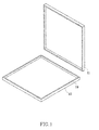
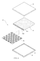
- the heat-dissipating device 10 comprising the upper casing 11, the lower casing 15, the capillary 21, the brace 25, the liquid working medium, and the crevice 18.
- the receiving space 19 is defined between the upper casing 11 and the lower casing 15.
- the capillary 21, the brace 25, and the liquid working medium are disposed in the receiving space 19.
- the capillary 21 has an upper portion 211 and a lower portion 212.
- the upper portion 211 is in contact with the bottom surface of the upper casing 11.
- the lower portion 212 is in contact with the top surface of the lower casing 15.
- the brace 25 is positioned between the upper portion 211 and the lower portion 212 and adapted to space apart the upper portion 211 and the lower portion 212.
- the liquid working medium is of predetermined quantity.
- the capillary 21 and the brace 25 are sintered to thereby be coupled to the upper casing 11 and the lower casing 15.
- the crevice 18 is formed by welding a seam between the upper and lower casings 11, 15 and sealed hermetically by high-energy welding.
- the seam between the upper and lower casings 11,15 is sealed hermetically.
- the upper portion 211 and the lower portion 212 of the capillary 21 in the receiving space 19 defined between the upper and lower casings 11,15 are in contact with inner surfaces of the upper and lower casings 11,15, respectively.
- the brace 25 spaces apart the upper portion 211 and the lower portion 212.
- the manufacturing method and the resultant structures in the first embodiment which have novelty over the prior art, not only feature absence of an exposed injection tube and thus reduction in required volume, but also feature satisfactory reliability and heat dissipation performance.
- the capillary is a metallic mesh which is illustrative of the present invention rather than restrictive of its constituent ingredients or structure.
- the capillary is a sintered copper powder.
- a sintered copper powder is a conventional element, and the way it is installed is disclosed in the prior art; hence, the sintered copper powder is not described herein in detail for the sake of brevity.
- an upper wick 32 is disposed on the bottom surface of the upper casing 31, and a lower wick 36 is disposed on the top surface of the lower casing 35.
- the upper wick 32 and the lower wick 36 are a plurality of grooves.
- the upper wick 32 and the lower wick 36 increase the channel of a liquid, such that the liquid working medium in the second embodiment has a better loop effect than the liquid working medium in the first embodiment.
- the upper wick and the lower wick are a plurality of grooves which are illustrative of the present invention rather than restrictive of their constituent ingredients or structure.
- the upper wick and the lower wick are a sintered copper powder or a metallic mesh.
- a sintered copper powder and a metallic mesh are conventional elements, and the way they are installed is disclosed in the prior art; hence, they are not described herein in detail for the sake of brevity.
- Step b) further involves positioning an upper auxiliary capillary 681 between the capillary 61 and the upper casing 51 and positioning a lower auxiliary capillary 682 between the capillary 61 and the lower casing 55 while positioning a capillary 61 and a brace 65 in the receiving space 59.
- the upper auxiliary capillary 681 and the lower auxiliary capillary 682 are a metallic mesh or a sintered copper powder.
- the upper auxiliary capillary 681 and the lower auxiliary capillary 682 are a metallic mesh to serve an illustrative purpose.
- the third embodiment features an upper auxiliary capillary 681 and a lower auxiliary capillary 682 and thereby features a loop-like path of a liquid working medium, thus further enhancing the quick temperature uniformity.
- auxiliary capillary is disposed between the capillary and the upper and lower casings to increase the loop-like path. Understandably, two or more layers of auxiliary capillary are equivalent to a simple change to the third embodiment and thus should be covered by the claims of the present invention.
Landscapes
- Engineering & Computer Science (AREA)
- Mechanical Engineering (AREA)
- Physics & Mathematics (AREA)
- Thermal Sciences (AREA)
- General Engineering & Computer Science (AREA)
- Life Sciences & Earth Sciences (AREA)
- Sustainable Development (AREA)
- Microelectronics & Electronic Packaging (AREA)
- Cooling Or The Like Of Semiconductors Or Solid State Devices (AREA)
- Cooling Or The Like Of Electrical Apparatus (AREA)
Applications Claiming Priority (1)
| Application Number | Priority Date | Filing Date | Title |
|---|---|---|---|
| PCT/CN2012/070611 WO2013107026A1 (zh) | 2012-01-19 | 2012-01-19 | 无注液管的均温装置制造方法及以该制法制成的均温装置 |
Publications (3)
| Publication Number | Publication Date |
|---|---|
| EP2806242A1 true EP2806242A1 (de) | 2014-11-26 |
| EP2806242A4 EP2806242A4 (de) | 2015-10-21 |
| EP2806242B1 EP2806242B1 (de) | 2019-12-11 |
Family
ID=48798511
Family Applications (1)
| Application Number | Title | Priority Date | Filing Date |
|---|---|---|---|
| EP12865722.8A Active EP2806242B1 (de) | 2012-01-19 | 2012-01-19 | Herstellungsverfahren für eine temperaturausgleichsvorrichtung ohne flüssigkeitsinjektionsrohr und in diesem verfahren hergestellte temperaturausgleichsvorrichtung |
Country Status (6)
| Country | Link |
|---|---|
| US (1) | US20140014304A1 (de) |
| EP (1) | EP2806242B1 (de) |
| JP (1) | JP2015512020A (de) |
| KR (1) | KR20140116479A (de) |
| CA (1) | CA2861406A1 (de) |
| WO (1) | WO2013107026A1 (de) |
Cited By (1)
| Publication number | Priority date | Publication date | Assignee | Title |
|---|---|---|---|---|
| CN109870054A (zh) * | 2017-12-04 | 2019-06-11 | 泰硕电子股份有限公司 | 无除气管均温板制造方法 |
Families Citing this family (7)
| Publication number | Priority date | Publication date | Assignee | Title |
|---|---|---|---|---|
| WO2017015814A1 (zh) * | 2015-07-27 | 2017-02-02 | 金积德 | 板状均温装置 |
| US10012446B2 (en) | 2015-09-08 | 2018-07-03 | Acmecools Tech. Ltd. | Vapor chamber |
| CN111660025B (zh) * | 2019-12-27 | 2024-09-17 | 东莞市万维热传导技术有限公司 | 一种多腔式均温板的封口焊接方法 |
| CN113260218A (zh) * | 2020-02-09 | 2021-08-13 | 欣兴电子股份有限公司 | 均热板结构及其制作方法 |
| TWI888990B (zh) * | 2020-02-09 | 2025-07-01 | 欣興電子股份有限公司 | 均熱板結構及其製作方法 |
| CN114459268A (zh) * | 2020-11-09 | 2022-05-10 | 欣兴电子股份有限公司 | 均热板结构及其制作方法 |
| CN222514294U (zh) * | 2024-03-11 | 2025-02-21 | 讯强电子(惠州)有限公司 | 均热板、散热器 |
Family Cites Families (20)
| Publication number | Priority date | Publication date | Assignee | Title |
|---|---|---|---|---|
| JP2001074381A (ja) * | 1999-09-07 | 2001-03-23 | Furukawa Electric Co Ltd:The | 薄型平面型ヒートパイプおよびコンテナ |
| JP2002039693A (ja) * | 2000-07-21 | 2002-02-06 | Toufuji Denki Kk | フラット型ヒートパイプ |
| US6477045B1 (en) * | 2001-12-28 | 2002-11-05 | Tien-Lai Wang | Heat dissipater for a central processing unit |
| JP2004238672A (ja) * | 2003-02-05 | 2004-08-26 | Fujikura Ltd | 平板型ヒートパイプの製造方法 |
| TWI284190B (en) * | 2004-11-11 | 2007-07-21 | Taiwan Microloops Corp | Bendable heat spreader with metallic screens based micro-structure and method for fabricating same |
| CN1832156A (zh) * | 2005-03-09 | 2006-09-13 | 台达电子工业股份有限公司 | 散热装置的结构及其制造方法 |
| CN100437006C (zh) * | 2005-08-12 | 2008-11-26 | 富准精密工业(深圳)有限公司 | 热管之制造方法 |
| JP2007064523A (ja) * | 2005-08-30 | 2007-03-15 | Furukawa Electric Co Ltd:The | 圧接式平面型ヒートパイプ、製造装置およびその製造方法 |
| JP2008045820A (ja) * | 2006-08-17 | 2008-02-28 | Kiko Kagi Kofun Yugenkoshi | 平板式ヒートパイプの製造方法 |
| DE202007007568U1 (de) * | 2007-05-25 | 2007-09-20 | Boston Cool Tec Corporation, Wilmington | Eine flache Heatpipe (Wärmeleitrohr) und Kühlkörper welche diese verwenden |
| CN101394726A (zh) * | 2007-09-20 | 2009-03-25 | 常熟市睿镭电子科技有限公司 | 一种无注液管的传热装置的制造方法 |
| CN101451791B (zh) * | 2007-11-28 | 2011-09-21 | 贸晖科技股份有限公司 | 均温板及其制造方法 |
| CN101520286B (zh) * | 2008-02-27 | 2011-05-11 | 贸晖科技股份有限公司 | 均温板内部的支撑体、制法及均温板 |
| TWM347809U (en) * | 2008-05-26 | 2008-12-21 | Xu xiu cang | Fast temperature-averaging heat conductive device |
| TW200948506A (en) | 2008-05-26 | 2009-12-01 | Ji-De Jin | Heat transfer device having no liquid filled pipe and manufacturing method thereof |
| CN101605445B (zh) * | 2008-06-10 | 2011-06-22 | 金积德 | 无注液管的传热装置及其制法 |
| TW201024648A (en) * | 2008-12-26 | 2010-07-01 | Ji-De Jin | Flat loop heat pipe |
| CN201378002Y (zh) * | 2009-05-08 | 2010-01-06 | 中山大学 | 一种无注液管的相变传热器件 |
| CN101846471B (zh) * | 2010-05-15 | 2012-10-17 | 中山伟强科技有限公司 | 一种均热板 |
| JP3163111U (ja) * | 2010-07-16 | 2010-09-30 | 昆山巨仲電子有限公司 | 放熱板の毛細構造 |
-
2012
- 2012-01-19 WO PCT/CN2012/070611 patent/WO2013107026A1/zh not_active Ceased
- 2012-01-19 EP EP12865722.8A patent/EP2806242B1/de active Active
- 2012-01-19 KR KR1020147022117A patent/KR20140116479A/ko not_active Ceased
- 2012-01-19 CA CA2861406A patent/CA2861406A1/en not_active Abandoned
- 2012-01-19 US US13/823,702 patent/US20140014304A1/en not_active Abandoned
- 2012-01-19 JP JP2014552463A patent/JP2015512020A/ja active Pending
Cited By (1)
| Publication number | Priority date | Publication date | Assignee | Title |
|---|---|---|---|---|
| CN109870054A (zh) * | 2017-12-04 | 2019-06-11 | 泰硕电子股份有限公司 | 无除气管均温板制造方法 |
Also Published As
| Publication number | Publication date |
|---|---|
| US20140014304A1 (en) | 2014-01-16 |
| CA2861406A1 (en) | 2013-07-25 |
| EP2806242B1 (de) | 2019-12-11 |
| JP2015512020A (ja) | 2015-04-23 |
| EP2806242A4 (de) | 2015-10-21 |
| WO2013107026A1 (zh) | 2013-07-25 |
| KR20140116479A (ko) | 2014-10-02 |
Similar Documents
| Publication | Publication Date | Title |
|---|---|---|
| EP2806242A1 (de) | Herstellungsverfahren für eine temperaturausgleichsvorrichtung ohne flüssigkeitsinjektionsrohr und in diesem verfahren hergestellte temperaturausgleichsvorrichtung | |
| US20100108297A1 (en) | Heat Pipe and Making Method Thereof | |
| US20240302107A1 (en) | Vapor chamber and manufacturing method thereof | |
| TWI529364B (zh) | Ultra - thin temperature plate and its manufacturing method | |
| US20170312871A1 (en) | Assembly structure of heat pipe and vapor chamber and assembly method threreof | |
| CN106197104A (zh) | 三维立体热超导均温散热体及其制备方法 | |
| JP2006140435A (ja) | 金属ワイヤメッシュの微小構造を備えた屈曲可能なヒートスプレッダーとヒートスプレッダーの製造方法 | |
| US20170314873A1 (en) | Heat conduction module structure and method of manufacturing the same | |
| TW202100938A (zh) | 均溫板及其製造方法 | |
| US9987712B2 (en) | Manufacturing method of flat-plate heat pipe | |
| KR20180021145A (ko) | 플레이트형 온도 균일화 장치 | |
| KR100688728B1 (ko) | 판형 열전달 장치의 케이스 접합 방법 및 이를 이용하여제조된 장치 | |
| JP2014109401A (ja) | ヒートパイプとその製造方法 | |
| TWI535990B (zh) | A larger heat pipe at one end and a manufacturing method thereof | |
| TW201331538A (zh) | 無注液管之均溫裝置製造方法及以該製法製成的物 | |
| CN106403674B (zh) | 板状均温装置 | |
| CN117870425B (zh) | 一种环路热管相变散热装置及其制造方法 | |
| WO2006115326A1 (en) | Case bonding method for a flat plate heat spreader by brazing and a heat spreader apparatus thereof | |
| KR100468396B1 (ko) | 판형 히트 파이프 | |
| CN100453957C (zh) | 平板式热管及其制造方法与封装单元 | |
| CN100384313C (zh) | 气密性腔体散热结构 | |
| TW200948506A (en) | Heat transfer device having no liquid filled pipe and manufacturing method thereof | |
| CN113357950A (zh) | 一种散热器及其制造方法 | |
| CN205303440U (zh) | Igbt内置多台架电极陶瓷封装外壳 | |
| CN223274387U (zh) | 立体均温板结合结构 |
Legal Events
| Date | Code | Title | Description |
|---|---|---|---|
| PUAI | Public reference made under article 153(3) epc to a published international application that has entered the european phase |
Free format text: ORIGINAL CODE: 0009012 |
|
| 17P | Request for examination filed |
Effective date: 20140708 |
|
| AK | Designated contracting states |
Kind code of ref document: A1 Designated state(s): AL AT BE BG CH CY CZ DE DK EE ES FI FR GB GR HR HU IE IS IT LI LT LU LV MC MK MT NL NO PL PT RO RS SE SI SK SM TR |
|
| DAX | Request for extension of the european patent (deleted) | ||
| RA4 | Supplementary search report drawn up and despatched (corrected) |
Effective date: 20150923 |
|
| RIC1 | Information provided on ipc code assigned before grant |
Ipc: F28F 3/02 20060101ALI20150917BHEP Ipc: B23P 15/00 20060101ALI20150917BHEP Ipc: B21D 53/02 20060101ALI20150917BHEP Ipc: F28D 15/04 20060101ALI20150917BHEP Ipc: H01L 23/427 20060101ALI20150917BHEP Ipc: F28D 15/02 20060101AFI20150917BHEP |
|
| STAA | Information on the status of an ep patent application or granted ep patent |
Free format text: STATUS: EXAMINATION IS IN PROGRESS |
|
| 17Q | First examination report despatched |
Effective date: 20190104 |
|
| GRAP | Despatch of communication of intention to grant a patent |
Free format text: ORIGINAL CODE: EPIDOSNIGR1 |
|
| STAA | Information on the status of an ep patent application or granted ep patent |
Free format text: STATUS: GRANT OF PATENT IS INTENDED |
|
| INTG | Intention to grant announced |
Effective date: 20190712 |
|
| GRAS | Grant fee paid |
Free format text: ORIGINAL CODE: EPIDOSNIGR3 |
|
| GRAA | (expected) grant |
Free format text: ORIGINAL CODE: 0009210 |
|
| STAA | Information on the status of an ep patent application or granted ep patent |
Free format text: STATUS: THE PATENT HAS BEEN GRANTED |
|
| AK | Designated contracting states |
Kind code of ref document: B1 Designated state(s): AL AT BE BG CH CY CZ DE DK EE ES FI FR GB GR HR HU IE IS IT LI LT LU LV MC MK MT NL NO PL PT RO RS SE SI SK SM TR |
|
| REG | Reference to a national code |
Ref country code: GB Ref legal event code: FG4D |
|
| REG | Reference to a national code |
Ref country code: CH Ref legal event code: EP |
|
| REG | Reference to a national code |
Ref country code: AT Ref legal event code: REF Ref document number: 1212605 Country of ref document: AT Kind code of ref document: T Effective date: 20191215 |
|
| REG | Reference to a national code |
Ref country code: DE Ref legal event code: R096 Ref document number: 602012066463 Country of ref document: DE |
|
| REG | Reference to a national code |
Ref country code: IE Ref legal event code: FG4D |
|
| REG | Reference to a national code |
Ref country code: NL Ref legal event code: MP Effective date: 20191211 |
|
| REG | Reference to a national code |
Ref country code: LT Ref legal event code: MG4D |
|
| PG25 | Lapsed in a contracting state [announced via postgrant information from national office to epo] |
Ref country code: GR Free format text: LAPSE BECAUSE OF FAILURE TO SUBMIT A TRANSLATION OF THE DESCRIPTION OR TO PAY THE FEE WITHIN THE PRESCRIBED TIME-LIMIT Effective date: 20200312 Ref country code: NO Free format text: LAPSE BECAUSE OF FAILURE TO SUBMIT A TRANSLATION OF THE DESCRIPTION OR TO PAY THE FEE WITHIN THE PRESCRIBED TIME-LIMIT Effective date: 20200311 Ref country code: LT Free format text: LAPSE BECAUSE OF FAILURE TO SUBMIT A TRANSLATION OF THE DESCRIPTION OR TO PAY THE FEE WITHIN THE PRESCRIBED TIME-LIMIT Effective date: 20191211 Ref country code: ES Free format text: LAPSE BECAUSE OF FAILURE TO SUBMIT A TRANSLATION OF THE DESCRIPTION OR TO PAY THE FEE WITHIN THE PRESCRIBED TIME-LIMIT Effective date: 20191211 Ref country code: SE Free format text: LAPSE BECAUSE OF FAILURE TO SUBMIT A TRANSLATION OF THE DESCRIPTION OR TO PAY THE FEE WITHIN THE PRESCRIBED TIME-LIMIT Effective date: 20191211 Ref country code: LV Free format text: LAPSE BECAUSE OF FAILURE TO SUBMIT A TRANSLATION OF THE DESCRIPTION OR TO PAY THE FEE WITHIN THE PRESCRIBED TIME-LIMIT Effective date: 20191211 Ref country code: FI Free format text: LAPSE BECAUSE OF FAILURE TO SUBMIT A TRANSLATION OF THE DESCRIPTION OR TO PAY THE FEE WITHIN THE PRESCRIBED TIME-LIMIT Effective date: 20191211 Ref country code: BG Free format text: LAPSE BECAUSE OF FAILURE TO SUBMIT A TRANSLATION OF THE DESCRIPTION OR TO PAY THE FEE WITHIN THE PRESCRIBED TIME-LIMIT Effective date: 20200311 |
|
| PG25 | Lapsed in a contracting state [announced via postgrant information from national office to epo] |
Ref country code: RS Free format text: LAPSE BECAUSE OF FAILURE TO SUBMIT A TRANSLATION OF THE DESCRIPTION OR TO PAY THE FEE WITHIN THE PRESCRIBED TIME-LIMIT Effective date: 20191211 Ref country code: HR Free format text: LAPSE BECAUSE OF FAILURE TO SUBMIT A TRANSLATION OF THE DESCRIPTION OR TO PAY THE FEE WITHIN THE PRESCRIBED TIME-LIMIT Effective date: 20191211 |
|
| PG25 | Lapsed in a contracting state [announced via postgrant information from national office to epo] |
Ref country code: AL Free format text: LAPSE BECAUSE OF FAILURE TO SUBMIT A TRANSLATION OF THE DESCRIPTION OR TO PAY THE FEE WITHIN THE PRESCRIBED TIME-LIMIT Effective date: 20191211 |
|
| PG25 | Lapsed in a contracting state [announced via postgrant information from national office to epo] |
Ref country code: PT Free format text: LAPSE BECAUSE OF FAILURE TO SUBMIT A TRANSLATION OF THE DESCRIPTION OR TO PAY THE FEE WITHIN THE PRESCRIBED TIME-LIMIT Effective date: 20200506 Ref country code: EE Free format text: LAPSE BECAUSE OF FAILURE TO SUBMIT A TRANSLATION OF THE DESCRIPTION OR TO PAY THE FEE WITHIN THE PRESCRIBED TIME-LIMIT Effective date: 20191211 Ref country code: NL Free format text: LAPSE BECAUSE OF FAILURE TO SUBMIT A TRANSLATION OF THE DESCRIPTION OR TO PAY THE FEE WITHIN THE PRESCRIBED TIME-LIMIT Effective date: 20191211 Ref country code: CZ Free format text: LAPSE BECAUSE OF FAILURE TO SUBMIT A TRANSLATION OF THE DESCRIPTION OR TO PAY THE FEE WITHIN THE PRESCRIBED TIME-LIMIT Effective date: 20191211 Ref country code: RO Free format text: LAPSE BECAUSE OF FAILURE TO SUBMIT A TRANSLATION OF THE DESCRIPTION OR TO PAY THE FEE WITHIN THE PRESCRIBED TIME-LIMIT Effective date: 20191211 |
|
| PG25 | Lapsed in a contracting state [announced via postgrant information from national office to epo] |
Ref country code: IS Free format text: LAPSE BECAUSE OF FAILURE TO SUBMIT A TRANSLATION OF THE DESCRIPTION OR TO PAY THE FEE WITHIN THE PRESCRIBED TIME-LIMIT Effective date: 20200411 Ref country code: SK Free format text: LAPSE BECAUSE OF FAILURE TO SUBMIT A TRANSLATION OF THE DESCRIPTION OR TO PAY THE FEE WITHIN THE PRESCRIBED TIME-LIMIT Effective date: 20191211 Ref country code: SM Free format text: LAPSE BECAUSE OF FAILURE TO SUBMIT A TRANSLATION OF THE DESCRIPTION OR TO PAY THE FEE WITHIN THE PRESCRIBED TIME-LIMIT Effective date: 20191211 |
|
| REG | Reference to a national code |
Ref country code: CH Ref legal event code: PL |
|
| REG | Reference to a national code |
Ref country code: DE Ref legal event code: R097 Ref document number: 602012066463 Country of ref document: DE |
|
| PG25 | Lapsed in a contracting state [announced via postgrant information from national office to epo] |
Ref country code: MC Free format text: LAPSE BECAUSE OF FAILURE TO SUBMIT A TRANSLATION OF THE DESCRIPTION OR TO PAY THE FEE WITHIN THE PRESCRIBED TIME-LIMIT Effective date: 20191211 |
|
| REG | Reference to a national code |
Ref country code: AT Ref legal event code: MK05 Ref document number: 1212605 Country of ref document: AT Kind code of ref document: T Effective date: 20191211 Ref country code: BE Ref legal event code: MM Effective date: 20200131 |
|
| PLBE | No opposition filed within time limit |
Free format text: ORIGINAL CODE: 0009261 |
|
| STAA | Information on the status of an ep patent application or granted ep patent |
Free format text: STATUS: NO OPPOSITION FILED WITHIN TIME LIMIT |
|
| PG25 | Lapsed in a contracting state [announced via postgrant information from national office to epo] |
Ref country code: LU Free format text: LAPSE BECAUSE OF NON-PAYMENT OF DUE FEES Effective date: 20200119 Ref country code: DK Free format text: LAPSE BECAUSE OF FAILURE TO SUBMIT A TRANSLATION OF THE DESCRIPTION OR TO PAY THE FEE WITHIN THE PRESCRIBED TIME-LIMIT Effective date: 20191211 |
|
| 26N | No opposition filed |
Effective date: 20200914 |
|
| PG25 | Lapsed in a contracting state [announced via postgrant information from national office to epo] |
Ref country code: BE Free format text: LAPSE BECAUSE OF NON-PAYMENT OF DUE FEES Effective date: 20200131 Ref country code: AT Free format text: LAPSE BECAUSE OF FAILURE TO SUBMIT A TRANSLATION OF THE DESCRIPTION OR TO PAY THE FEE WITHIN THE PRESCRIBED TIME-LIMIT Effective date: 20191211 Ref country code: CH Free format text: LAPSE BECAUSE OF NON-PAYMENT OF DUE FEES Effective date: 20200131 Ref country code: PL Free format text: LAPSE BECAUSE OF FAILURE TO SUBMIT A TRANSLATION OF THE DESCRIPTION OR TO PAY THE FEE WITHIN THE PRESCRIBED TIME-LIMIT Effective date: 20191211 Ref country code: SI Free format text: LAPSE BECAUSE OF FAILURE TO SUBMIT A TRANSLATION OF THE DESCRIPTION OR TO PAY THE FEE WITHIN THE PRESCRIBED TIME-LIMIT Effective date: 20191211 Ref country code: LI Free format text: LAPSE BECAUSE OF NON-PAYMENT OF DUE FEES Effective date: 20200131 |
|
| PG25 | Lapsed in a contracting state [announced via postgrant information from national office to epo] |
Ref country code: IE Free format text: LAPSE BECAUSE OF NON-PAYMENT OF DUE FEES Effective date: 20200119 Ref country code: IT Free format text: LAPSE BECAUSE OF FAILURE TO SUBMIT A TRANSLATION OF THE DESCRIPTION OR TO PAY THE FEE WITHIN THE PRESCRIBED TIME-LIMIT Effective date: 20191211 |
|
| REG | Reference to a national code |
Ref country code: DE Ref legal event code: R081 Ref document number: 602012066463 Country of ref document: DE Owner name: CHIN, CHI-TE, TW Free format text: FORMER OWNER: ACMECOOLS TECH. LTD., TORTOLA, VG |
|
| REG | Reference to a national code |
Ref country code: GB Ref legal event code: 732E Free format text: REGISTERED BETWEEN 20211216 AND 20211222 |
|
| PG25 | Lapsed in a contracting state [announced via postgrant information from national office to epo] |
Ref country code: TR Free format text: LAPSE BECAUSE OF FAILURE TO SUBMIT A TRANSLATION OF THE DESCRIPTION OR TO PAY THE FEE WITHIN THE PRESCRIBED TIME-LIMIT Effective date: 20191211 Ref country code: MT Free format text: LAPSE BECAUSE OF FAILURE TO SUBMIT A TRANSLATION OF THE DESCRIPTION OR TO PAY THE FEE WITHIN THE PRESCRIBED TIME-LIMIT Effective date: 20191211 Ref country code: CY Free format text: LAPSE BECAUSE OF FAILURE TO SUBMIT A TRANSLATION OF THE DESCRIPTION OR TO PAY THE FEE WITHIN THE PRESCRIBED TIME-LIMIT Effective date: 20191211 |
|
| PG25 | Lapsed in a contracting state [announced via postgrant information from national office to epo] |
Ref country code: MK Free format text: LAPSE BECAUSE OF FAILURE TO SUBMIT A TRANSLATION OF THE DESCRIPTION OR TO PAY THE FEE WITHIN THE PRESCRIBED TIME-LIMIT Effective date: 20191211 |
|
| REG | Reference to a national code |
Ref country code: DE Ref legal event code: R082 Ref document number: 602012066463 Country of ref document: DE Representative=s name: STRAUS, ALEXANDER, DIPL.-CHEM.UNIV. DR.PHIL., DE |
|
| PGFP | Annual fee paid to national office [announced via postgrant information from national office to epo] |
Ref country code: GB Payment date: 20260122 Year of fee payment: 15 |
|
| PGFP | Annual fee paid to national office [announced via postgrant information from national office to epo] |
Ref country code: DE Payment date: 20260130 Year of fee payment: 15 |
|
| PGFP | Annual fee paid to national office [announced via postgrant information from national office to epo] |
Ref country code: FR Payment date: 20260123 Year of fee payment: 15 |