EP2806253A2 - Messanordnung zur Bestimmung einer Messgröße - Google Patents
Messanordnung zur Bestimmung einer Messgröße Download PDFInfo
- Publication number
- EP2806253A2 EP2806253A2 EP14168541.2A EP14168541A EP2806253A2 EP 2806253 A2 EP2806253 A2 EP 2806253A2 EP 14168541 A EP14168541 A EP 14168541A EP 2806253 A2 EP2806253 A2 EP 2806253A2
- Authority
- EP
- European Patent Office
- Prior art keywords
- current
- measuring arrangement
- load current
- control device
- value
- Prior art date
- Legal status (The legal status is an assumption and is not a legal conclusion. Google has not performed a legal analysis and makes no representation as to the accuracy of the status listed.)
- Granted
Links
Images
Classifications
-
- G—PHYSICS
- G01—MEASURING; TESTING
- G01D—MEASURING NOT SPECIALLY ADAPTED FOR A SPECIFIC VARIABLE; ARRANGEMENTS FOR MEASURING TWO OR MORE VARIABLES NOT COVERED IN A SINGLE OTHER SUBCLASS; TARIFF METERING APPARATUS; MEASURING OR TESTING NOT OTHERWISE PROVIDED FOR
- G01D21/00—Measuring or testing not otherwise provided for
-
- G—PHYSICS
- G01—MEASURING; TESTING
- G01R—MEASURING ELECTRIC VARIABLES; MEASURING MAGNETIC VARIABLES
- G01R19/00—Arrangements for measuring currents or voltages or for indicating presence or sign thereof
- G01R19/0092—Measuring current only
-
- G—PHYSICS
- G01—MEASURING; TESTING
- G01L—MEASURING FORCE, STRESS, TORQUE, WORK, MECHANICAL POWER, MECHANICAL EFFICIENCY, OR FLUID PRESSURE
- G01L21/00—Vacuum gauges
-
- G—PHYSICS
- G08—SIGNALLING
- G08C—TRANSMISSION SYSTEMS FOR MEASURED VALUES, CONTROL OR SIMILAR SIGNALS
- G08C19/00—Electric signal transmission systems
- G08C19/02—Electric signal transmission systems in which the signal transmitted is magnitude of current or voltage
-
- H—ELECTRICITY
- H04—ELECTRIC COMMUNICATION TECHNIQUE
- H04Q—SELECTING
- H04Q9/00—Arrangements in telecontrol or telemetry systems for selectively calling a substation from a main station, in which substation desired apparatus is selected for applying a control signal thereto or for obtaining measured values therefrom
Definitions
- the invention relates to a measuring arrangement for determining at least one measured variable.
- the measuring arrangement has at least one sensor device, at least one signal output for outputting at least one output signal and at least one current adjusting device for adjusting the current intensity of the output signal.
- the aforementioned measured variable is, for example, the flow, the level, the pH, the electrical conductivity or the temperature of a medium.
- the output signal is preferably a current signal, so that the output signal carries information about the value of the measured variable or a state of the measuring arrangement in the form of the current intensity.
- the output signal is therefore in particular a so-called 4 ... 20 mA signal.
- the measuring arrangement is, for example, a field or measuring device for use in the field of process automation. Alternatively, the measuring arrangement is a combination of separately configured components.
- measuring devices are used in modern process automation as so-called field devices for the determination or monitoring of measured variables in order to be able to monitor or control processes accordingly.
- such measuring devices are designed as compact units or have individual, remote components that are connected to one another for the transmission of information or energy.
- such measuring arrangements have at least one sensor device which serves for the actual determination of the measured variable and often usually generates a primary signal that is dependent on the measured variable and often electrical.
- the actual value of the measured variable can then be determined from the primary signal or a variable derived therefrom. This happens partly in the measuring arrangement itself or in a higher-level unit, such as a control room.
- stored calibration data are required or different primary signals are calculated.
- the radar principle is determined, for example, from the transit time of a microwave signal via reference data-in particular via the distance between an antenna used for the measurement and the tank in which the measuring medium is located-the level of the medium reflecting the microwave signals.
- the functional section for obtaining the value of the measured quantity or for processing or converting the primary signal which is thus arranged downstream of the sensor device and generates the output signal output via the signal output, is also used as a transmitter, in particular in those measuring arrangements which have separate or separable components designated.
- a signal output e.g. B. provided in the form of an interface.
- the output signal is analog or digital, for example.
- the current intensity of the output signal - between 4 mA and 20 mA - serves as a carrier in the information to be output, for example, by assigning the smallest current value to the smallest expected measured value and the largest current value to the largest expected measured value. Between these limits, a linear correlation between current and measured value is often used.
- output signals are generated with currents outside the 4 to 20 mA range.
- the field device Since the output signals are between 4 mA and 20 mA, the field device is only each a corresponding current and therefore a changing power available. The power available for the operation of the field device depends on the measured value. Therefore, the electronics of the measuring arrangement or the control of the components must be interpreted accordingly. In many measuring arrangements, the aim is that under all operating conditions - d. H. with all possible measurements - the energy consumption is always maximum.
- the output signals according to the 4 ... 20 mA standard are analogue signals.
- a variant to enable digital communication is the so-called HART standard (Highway Addressable Remote Transducer).
- the digital signals are superimposed on the analog signal. If a measuring arrangement should also enable a signal output according to the HART standard, then it is necessary for the signal output or the current input to have a high input resistance.
- the published patent DE 199 25 943 A1 can be found a generic measuring arrangement, which consists of a measured value sensing part with a sensor device and a power control device, from a measured value evaluation part - ie a kind of transmitter - and a connection between the two.
- the power adjusting device adjusts the current according to the measured value, which is done by the direct control by the sensor device. In this case, the current consumption of the sensor device is controlled so that a voltage drop across the current adjusting device is as small as possible.
- a field device electronics for two-wire devices describes the published patent application DE 10 2006 030 962 A1 ,
- the electronics serve in the event that the energy available to the field device is not required by the sensor device, the excess energy is converted into heat.
- several partial flows are measured within the field device, consumers are turned off and is set via an actuator, which also serves to limit the voltage to be converted into heat current.
- the structure is very detailed, very complex and thus costly. In particular, several current measurements are performed.
- the invention has for its object to propose a measuring arrangement whose power consumption is maximum in all operating conditions.
- the measurement arrangement according to the invention in which the previously derived and indicated object is achieved, is initially and essentially characterized in that at least one load current device and at least one control device are provided.
- the control device controls the load current device at least on the basis of a voltage drop across the current setting device.
- the measuring arrangement according to the invention is configured in particular as a two-conductor device, so that the signal output in particular also serves to supply energy to the measuring arrangement.
- the power adjusting device is used to adjust the output signal with respect to the current. This is done in a variant in that the current adjusting device adjusts a variable component of the current intensity, which in combination with a fixed component - as an offset - adds up to the value of the current value of the output signal to be set and, in particular, dependent on the measured value.
- the control device controls a load current device in response to a voltage drop across the current setting device.
- the load current device is, in particular, a device via which a load current can be dissipated or dissipated into heat.
- the power control device, the control device and the load current device components of the measuring arrangement, the subordinate actual sensor device and are combined in an additional embodiment even in a so-called transmitter.
- the power adjusting device connects to a contact of the signal output.
- only the voltage across the current setting device is regulated so that this current setting device or at least one component of the current setting device does not come to saturation.
- the electrical voltage is tapped on each side of a transistor - as the crucial part of the current setting device in this embodiment - via a voltage divider (as an array of electrical resistance elements) and the two voltages are compared with each other via an operational amplifier.
- a resulting deviation between the two voltage values - in total as a measure of the voltage drop across the current setting device - is then compensated in this embodiment via a load transistor as part of the load current device.
- the load current device consumes the portion of the current that is not required by the sensor device. Therefore, the power consumption regardless of the operating state - ie the value of the measured variable - always be maximum.
- the control of the load current device as a function of the voltage drop across the current adjusting device takes place in one embodiment If the voltage drop across the current setting device drops, this results from the fact that the downstream electronics and in particular the sensor device does not require all the available power, but only a part. Therefore, the load current device is controlled to increase its power consumption. Conversely, if the voltage drop across the current setting device increases, more power is consumed by the sensor device and the current consumption by the load current device is suitably reduced.
- Such a controller has the advantage, for example, that the current setting device has a transistor, that this transistor is kept in normal operation and can not come into saturation. Via the latter, it is again achieved that the input resistance of the signal output, which coincides with the energy input in a two-wire device, remains at a correspondingly high predetermined value, so that the application of the HART protocol for data communication is possible.
- the current setting device and the load current device are connected in series, and in an alternative or additional embodiment, the current setting device and the control device are connected in parallel with each other.
- the power control device is controlled by at least one default device in the sense that the power control device receives from the default device, the information about which current strength of the output signal is set.
- the controller is dependent at least on a value generated by the sensor device. In one embodiment, this value is, in particular, the value of the measured variable to be determined and, in an alternative embodiment, a value obtained by the sensor device during the measurement, which results in the value of the measured variable to be determined via appropriate processing.
- the sensor device generates a value that may already be the final value of the measured variable or, if necessary, a further evaluation and processing z. B. in conjunction with calibration data needed. Based on this value of the sensor device controls the default device, the power adjusting device and thereby sets the value of the current of the output signal.
- the adjustment of the current intensity is done in one embodiment such that the current strength of the output signal is the sum of the variable portion of the current adjusting device and a fixed portion of an additional device for adjusting the current - a Feststromstellvorraum -.
- the presetting device additionally monitors the output signal in one embodiment and compares the current present at the signal output and thus at the two lines / contacts / terminals of the measuring arrangement with the predetermined desired value of the output signal.
- a sense resistor is used for reading back the set current.
- the default device and the control device are configured such that they operate independently of each other.
- the control device therefore controls, in particular, the load current device only as a function of the voltage drop across the current setting device and therefore independently of the presetting device and also in such a way that the values of the sensor device are not transmitted to the regulating device.
- the presetting device receives the information about the output signal to be set from the sensor device and, based thereon, controls the current setting device.
- the control device in turn monitors the voltage drop across the power control device and, based thereon, controls the load current device, unaffected by the value of the sensor device or the default by the default device.
- the load current device is at least partially designed as a power consumer.
- the load current device is used in particular for the consumption of electrical energy which is not required or consumed in the given operating state (ie the state with the respectively determined value of the measured variable and depending on the respective value of the current intensity of the output signal), in particular by the sensor device.
- the consumption of superfluous energy by the load current device is controlled in response to the voltage drop across the power control device.
- the load current device has at least one transistor.
- control is dedicated to the embodiment in which the control device controls the load current device in such a way that with decreasing voltage drop across the power control device consumption of electrical energy increases through the load current device.
- control device controls the load current device in such a way that, as the voltage drop across the current setting device increases, a consumption of electrical energy by the load current device decreases.
- the further measuring arrangement is dedicated to the embodiment, which is provided according to at least one fixed current setting device, which adjusts a predefinable fixed value for the current intensity of the output signal.
- the total value of the current value of the output signal results from the fixed value set by the fixed current setting device and from a variable value set by the current setting device.
- the fixed-current actuating device serves in particular also as a starting current source in order to ensure a basic operation of the measuring arrangement. This in particular for the case that the power control device or in particular a transistor can not be controlled as part of the power control device without already existing energy.
- the current adjusting device has at least one transistor.
- the control device controls the load current device such that the transistor of the current adjusting device remains out of saturation. In this embodiment, it is ensured that the transistor does not saturate and thus would no longer be controllable.
- the embodiment with a transistor in the current setting device can be combined in particular with the embodiment in which the current setting device and the load current device are in series as consumers of electrical energy. By the corresponding control of the load current device by the control device, the saturation of the transistor is prevented.
- preventing saturation also ensures that the input resistance of the signal output always remains high and does not drop.
- the load current device is connected in parallel to the signal output and parallel to the sensor device.
- the sensor device of the flow measurement according to the vortex principle is used.
- An alternative embodiment provides that the flow is measured as a measured variable by an MID sensor device or according to the Coriolis flow measurement principle.
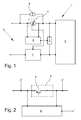
- FIG. 1 an embodiment of a measuring arrangement 1 is shown, wherein the figure is not a representation in the sense of a correct electrical circuit diagram, but rather reveal the interactions between the different components of the measuring arrangement 1.
- the Fig. 2 shows a part of the measuring arrangement 1 of Fig. 1
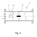
- Fig. 3 additionally shows an example of a sensor device 2 schematically.
- the Fig. 1 schematically shows the structure of a measuring arrangement 1, which is designed here in particular as a compact, one-piece field device.
- a sensor device 2 is provided which, for example, serves to measure the flow of a flowable medium through a pipeline.
- the value of the measured variable determined by the measuring arrangement 1 is output via the signal output 3 as a 4... 20 mA signal. An assignment between the current value and the value of the measured variable is used. Since the field device is designed as a measuring arrangement 1 in the embodiment shown as a so-called two-wire device, the signal output 3 also serves as an input to electrical energy.
- the power adjustment device 4 For the setting of the current strength of the output signal and thus ultimately for the output of the value for the determination of the measured variable u. a. the power adjustment device 4 is provided.
- the respectively maximum available electrical energy is obtained for each measured value and therefore also for each operating state via the signal output 3.
- the signal output 3 also has the same output resistance in each operating state and thus has the same output resistance over the design of the signal output 3. This makes it possible to perform a data communication according to the HART standard via the signal output 3.
- a load current device 5 is arranged in series with the current setting device 4 in the illustrated implementation.
- the load current device 5 essentially serves to excess - so in particular unnecessary by the sensor device 2 - electrical Consuming energy and converting it into heat, for example.
- the load current device 5 is connected in parallel to the sensor device 2 in the embodiment shown.
- at least one - not shown here - transistor is provided as part of the load current device 5.
- the extent of the load current device 5 z. B. to be dissipated in heat electrical energy depends on the voltage drop across the power control device 4.
- the monitoring of the voltage drop and the outgoing control of the load current device 5 is carried out by the control device 6.
- the two voltages are then compared with one another via an operational amplifier (not illustrated here), the load current source 5 being suitably readjusted in the event of a deviation.
- the power adjusting device 4 is controlled by the presetting device 7, which receives from the sensor device 2 a value to be transmitted via the output signal.
- the proportion of the current that is set by the power adjusting device 4 is a variable proportion, which with a fixed portion, which is determined by the parallel to the power control device 4 fixed fixed position control device 8, adds up to the total current of the output signal, which corresponds to the value of Sensor device 2 and thus in the embodiment shown in particular also the value of the measured variable is assigned.
- the control device 6 and the default device 7 are executed independently of each other, and the value of the sensor device 2 does not reach the control device 6.
- the control device 6 monitors only the Voltage drop across the power control device 4 and also controls the load current device 5 only in response to this voltage drop.
- the current adjusting device 4 has at least one transistor 9. If the voltages are detected in front of and behind this transistor 9 and the respective adequate quantum of electrical energy is consumed by the load current device 5 in the event of a deviation of the voltages from one another, then in particular it can also be prevented that the transistor 9 saturates.
- the Fig. 3 shows as an example of a sensor device 2, a vortex flowmeter for flowable media (indicated by the arrows).
- the measuring principle of such measuring devices is based on the fact that in a flowable medium behind a bluff body 10, which is flowed around by the medium in a measuring tube 11, a so-called Karman vortex street can be formed which moves away from the bluff body 10 by itself with the flow detaching vertebrae is formed.
- the frequency with which the vortices detach from the bluff body 10 depends on the flow velocity, the relationship being almost linear under certain conditions.
Landscapes
- Physics & Mathematics (AREA)
- General Physics & Mathematics (AREA)
- Engineering & Computer Science (AREA)
- Computer Networks & Wireless Communication (AREA)
- Arrangements For Transmission Of Measured Signals (AREA)
- Measurement Of Current Or Voltage (AREA)
- Indication And Recording Devices For Special Purposes And Tariff Metering Devices (AREA)
- Measuring Instrument Details And Bridges, And Automatic Balancing Devices (AREA)
Abstract
Description
- Die Erfindung betrifft eine Messanordnung zur Bestimmung mindestens einer Messgröße. Die Messanordnung verfügt über mindestens eine Sensorvorrichtung, mindestens einen Signalausgang zur Ausgabe mindestens eines Ausgangssignals und mindestens eine Stromstellvorrichtung zur Einstellung der Stromstärke des Ausgangssignals.
- Bei der vorgenannten Messgröße handelt es sich beispielsweise um den Durchfluss, den Füllstand, den pH-Wert, die elektrische Leitfähigkeit oder die Temperatur eines Mediums. Das Ausgangssignal ist vorzugsweise ein Stromsignal, so dass das Ausgangssignal eine Information über den Wert der Messgröße bzw. einen Zustand der Messanordnung in Form der Stromstärke trägt. Das Ausgangssignal ist damit insbesondere ein sogenanntes 4...20 mA-Signal. Die Messanordnung ist beispielweise ein Feld- oder Messgerät für die Anwendung im Bereich der Prozessautomatisierung. Alternativ handelt es sich bei der Messanordnung um eine Kombination von separat ausgestalteten Komponenten.
- Unterschiedliche Messgeräte dienen in der modernen Prozessautomatisierung als sogenannte Feldgeräte der Bestimmung oder Überwachung von Messgrößen, um Prozesse entsprechend überwachen oder steuern zu können. Solche Messgeräte sind dabei teilweise als kompakte Einheiten ausgestaltet oder verfügen über einzelne, voneinander abgesetzte Komponenten, die für die Übertragung von Informationen bzw. Energie miteinander verbunden sind.
- Prinzipiell verfügen solche Messanordnungen zumindest über eine Sensorvorrichtung, die der eigentlichen Bestimmung der Messgröße dient und häufig zumeist ein von der Messgröße abhängiges und oft elektrisches Primärsignal erzeugt. Aus dem Primärsignal oder einer davon abgeleiteten Größe lässt sich dann der eigentliche Wert der Messgröße ermitteln. Dies geschieht teilweise in der Messanordnung selbst oder in einer übergeordneten Einheit, wie beispielsweise einer Leitwarte. Für die Gewinnung des Werts der Messgröße sind beispielsweise hinterlegte Kalibrierdaten erforderlich oder es werden unterschiedliche Primärsignale verrechnet. Bei der Füllstandmessung nach dem Radar-Prinzip wird beispielsweise aus der Laufzeit eines Mikrowellensignals über Referenzdaten - insbesondere über den Abstand zwischen einer für die Messung verwendeten Antenne und dem Tank, in dem sich das Messmedium befindet - der Füllstand des die Mikrowellensignale reflektierenden Mediums ermittelt.
- Der funktionelle Abschnitt zur Gewinnung des Werts der Messgröße oder zur Aufbereitung oder Umwandlung des Primärsignals, der damit der Sensorvorrichtung nachgeordnet ist und das über den Signalausgang auszugebende Ausgangssignal erzeugt, wird insbesondere bei solchen Messanordnungen, die über separate oder voneinander trennbare Komponenten verfügen, auch als Transmitter bezeichnet.
- Für die Ausgabe des Messwerts oder des Primärsignals der Sensorvorrichtung oder einer davon abhängigen Größe oder auch für die Ausgabe von Informationen über den Zustand der Messanordnung beispielsweise in Form von Fehlersignalen ist üblicherweise ein Signalausgang, z. B. in Form einer Schnittstelle vorgesehen.
- Das Ausgangssignal ist beispielsweise analog oder digital. In der Prozessautomatisierung ist insbesondere die Verwendung von sogenannten 4...20 mA-Signalen verbreitet. Dabei dient die Stromstärke des Ausgangssignals - zwischen 4 mA und 20 mA - als Trägerin der auszugebenden Information, indem beispielsweise die kleinste Stromstärke dem kleinsten zu erwartenden Messwert und die größte Stromstärke dem größten zu erwartenden Messwert zugeordnet sind. Zwischen diesen Grenzwerten wird häufig eine lineare Zuordnung zwischen Stromstärke und Messwert verwendet. Um Fehlerzustände zu signalisieren, werden Ausgangssignale mit Stromstärken außerhalb des 4 bis 20 mA-Bereichs erzeugt.
- Um den Aufwand für die Verkabelung und auch für die Ausgestaltung der Messanordnungen bzw. Feldgeräte zu reduzieren, sind sogenannte Zweileitergeräte bekannt. Bei diesen Feld- oder Messgeräten sind nur zwei Leiter vorgesehen, so dass die Datenkommunikation und die Energieversorgung des Geräts über die gleichen Leitungen erfolgt. Daher fallen bei solchen Geräten bzw. Anordnungen der Signalausgang und der Stromeingang zusammen.
- Da die Ausgangssignale zwischen 4 mA und 20 mA liegen, steht dem Feldgerät auch jeweils nur eine entsprechende Stromstärke und daher eine sich ändernde Leistung zur Verfügung. Die für den Betrieb des Feldgeräts vorhandene Leistung ist abhängig vom Messwert. Daher ist die Elektronik der Messanordnung bzw. die Steuerung der Komponenten entsprechend auszulegen. Bei vielen Messanordnungen wird angestrebt, dass bei allen Betriebszuständen - d. h. bei allen möglichen Messwerten - die Energieaufnahme stets maximal ist.
- Bei den Ausgangssignalen gemäß dem 4...20 mA-Standard handelt es sich um analoge Signale. In der Prozessmesstechnik ist eine Variante, um eine digitale Kommunikation zu ermöglichen, der sogenannte HART-Standard (Highway Addressable Remote Transducer). Dabei werden die digitalen Signale dem analogen Signal überlagert. Soll eine Messanordnung auch eine Signalausgabe gemäß dem HART-Standard ermöglichen, so ist es erforderlich, dass der Signalausgang bzw. der Stromeingang einen hohen Eingangswiderstand aufweist bzw. darstellt.
- Der Offenlegungsschrift
DE 199 25 943 A1 lässt sich eine gattungsgemäße Messanordnung entnehmen, die aus einem Messwerterfassungsteil mit einer Sensorvorrichtung und einer Stromstellvorrichtung, aus einem Messwertauswertungsteil - also einer Art Transmitter - und einer Verbindung zwischen beiden besteht. Die Stromstellvorrichtung stellt den Strom entsprechend dem Messwert ein, was durch die direkte Steuerung durch die Sensorvorrichtung geschieht. Dabei wird die Stromaufnahme der Sensorvorrichtung so gesteuert, dass ein Spannungsabfall über die Stromstellvorrichtung möglichst klein ist. - Eine Feldgerät-Elektronik für Zweileitergeräte beschreibt die Offenlegungsschrift
DE 10 2006 030 962 A1 . Die Elektronik dient dazu, in dem Fall, dass die dem Feldgerät zur Verfügung stehende Energie nicht von der Sensorvorrichtung benötigt wird, die überschüssige Energie in Wärme umgewandelt wird. Dabei werden mehrere Teilströme innerhalb des Feldgeräts gemessen, werden Verbraucher abgeschaltet und wird über ein Stellglied, das auch der Spannungsbegrenzung dient, der in Wärme umzuwandelnde Strom eingestellt. Der Aufbau ist insgesamt sehr detailliert, sehr aufwändig und damit kostenintensiv. Insbesondere werden mehrere Strommessungen durchgeführt. - In der Offenlegungsschrift
DE 10 2008 062 815 A1 wird eine Schaltung beschrieben, mit der bei einem Zweileitergerät überschüssige elektrische Energie nicht verbraucht, sondern gespeichert wird. - Der Erfindung liegt die Aufgabe zugrunde, eine Messanordnung vorzuschlagen, deren Leistungsaufnahme bei möglichst allen Betriebszuständen maximal ist.
- Die erfindungsgemäße Messanordnung, bei der die zuvor hergeleitete und aufgezeigte Aufgabe gelöst ist, ist zunächst und im Wesentlichen dadurch gekennzeichnet, dass mindestens eine Laststromvorrichtung und mindestens eine Regelvorrichtung vorgesehen sind. Dabei steuert die Regelvorrichtung mindestens ausgehend von einem Spannungsabfall über der Stromstellvorrichtung die Laststromvorrichtung.
- Die erfindungsgemäße Messanordnung ist in einer Ausgestaltung insbesondere als Zweileitergerät ausgestaltet, so dass der Signalausgang insbesondere auch der Energieversorgung der Messanordnung dient.
- Die Stromstellvorrichtung dient der Einstellung des Ausgangssignals in Bezug auf die Stromstärke. Dies erfolgt in einer Variante dadurch, dass die Stromstellvorrichtung einen variablen Anteil der Stromstärke einstellt, der sich in Verbindung mit einem festen Anteil - gleichsam als Offset - insgesamt zu dem einzustellenden und insbesondere von dem Messwert abhängigen Wert der Stromstärke des Ausgangssignals ergänzt.
- Die Regelvorrichtung steuert eine Laststromvorrichtung in Abhängigkeit von einem Spannungsabfall über der Stromstellvorrichtung. Bei der Laststromvorrichtung handelt es sich insbesondere um eine Vorrichtung, über die ein Laststrom abgeführt bzw. in Wärme dissipiert werden kann.
- In einer Ausgestaltung sind die Stromstellvorrichtung, die Regelvorrichtung und die Laststromvorrichtung Komponenten der Messanordnung, die der eigentlichen Sensorvorrichtung nachgeordnet und in einer zusätzlichen Ausgestaltung sogar in einem sogenannten Transmitter zusammengefasst sind. In einer Ausgestaltung schließt sich die Stromstellvorrichtung einem Kontakt des Signalausgangs an.
- Im Gegensatz zum Stand der Technik wird für die Steuerung des Verbrauchs der überschüssigen Energie lediglich ein Spannungsabfall bestimmt bzw. überwacht. Eine Messung von Teilströmen innerhalb der Messanordnung wie im Stand der Technik entfällt. Auch wird die interne Spannung nicht begrenzt.
- In einer Ausgestaltung wird insbesondere lediglich die Spannung über der Stromstellvorrichtung geregelt, damit diese Stromstellvorrichtung bzw. wenigstens eine Komponente der Stromstellvorrichtung nicht in die Sättigung kommt.
- In einer Ausgestaltung wird zu beiden Seiten eines Transistors - als dem in dieser Ausgestaltung entscheidenden Bestandteil der Stromstellvorrichtung - die elektrische Spannung über jeweils einen Spannungsteiler (als einer Anordnung von elektrischen Widerstandselementen) abgegriffen und werden die beiden Spannungen über einen Operationsverstärker miteinander verglichen. Eine sich ergebende Abweichung zwischen den beiden Spannungswerten - insgesamt als Maß für die über der Stromstellvorrichtung abfallende Spannung - wird dann in dieser Ausgestaltung über einen Lasttransistor als Teil der Laststromvorrichtung ausgeglichen. Durch die Verwendung des Spannungsteilers ergibt sich keine feste Spannungsdifferenz über dem Transistor der Stromstellvorrichtung. Die Spannungsdifferenz wächst aufgrund der Teilerverhältnisse der Spannungsteiler zu höheren Spannungen am Signalausgang - den sogenannten Klemmenspannungen - leicht an.
- Durch die Laststromvorrichtung wird der Anteil des Stromes, der nicht von der Sensorvorrichtung benötigt wird, verbraucht. Daher kann die Leistungsaufnahme auch unabhängig vom Betriebszustand - also dem Wert der Messgröße - stets maximal sein.
- Die Steuerung der Laststromvorrichtung in Abhängigkeit von der über die Stromstellvorrichtung abfallende Spannung erfolgt in einer Ausgestaltung wie folgt: Sinkt der Spannungsabfall über der Stromstellvorrichtung, so resultiert dies daraus, dass die nachfolgende Elektronik und insbesondere die Sensorvorrichtung nicht den ganzen zur Verfügung stehenden Strom, sondern nur einen Teil benötigt. Daher wird die Laststromvorrichtung so gesteuert, dass sich ihr Energieverbrauch erhöht. Steigt umgekehrt die über der Stromstellvorrichtung abfallende Spannung, so wird von der Sensorvorrichtung mehr Strom verbraucht und die Stromaufnahme durch die Laststromvorrichtung wird passend reduziert.
- Eine solche Steuerung hat beispielsweise für die Ausgestaltung, dass die Stromstellvorrichtung über einen Transistor verfügt, den Vorteil, dass dieser Transistor im Regelbetrieb gehalten wird und nicht in die Sättigung kommen kann. Über Letzteres wird wiederum erzielt, dass der Eingangswiderstand des Signalausgangs, der mit dem Energieeingang bei einem Zweileitergerät zusammenfällt, auf einem entsprechend hoch vorgegebenen Wert bleibt, so dass die Anwendung des HART-Protokolls zur Datenkommunikation möglich ist.
- In einer Ausgestaltung sind die Stromstellvorrichtung und die Laststromvorrichtung in Reihe geschaltet und in einer alternativen oder ergänzenden Ausgestaltung sind die Stromstellvorrichtung und die Regelvorrichtung parallel zueinander geschaltet.
- In einer Ausgestaltung wird die Stromstellvorrichtung von mindestens einer Vorgabevorrichtung in dem Sinne gesteuert, dass die Stromstellvorrichtung von der Vorgabevorrichtung die Informationen darüber erhält, welche Stromstärke des Ausgangssignals einzustellen ist. Dabei ist die Steuerung abhängig zumindest von einem von der Sensorvorrichtung erzeugten Wert. Dieser Wert ist in einer Ausgestaltung insbesondere der Wert der zu bestimmenden Messgröße und in einer alternativen Ausgestaltung ein von der Sensorvorrichtung bei der Messung gewonnener Wert, der über eine passende Verarbeitung den Wert der zu bestimmenden Messgröße ergibt.
- Bei der vorhergehenden Ausgestaltung erzeugt die Sensorvorrichtung einen Wert, der ggf. bereits der endgültige Wert der Messgröße ist oder der ggf. einer weiterer Auswertung und Aufarbeitung z. B. in Verbindung mit Kalibrierdaten bedarf. Ausgehend von diesem Wert der Sensorvorrichtung steuert die Vorgabevorrichtung die Stromstellvorrichtung und stellt dadurch den Wert der Stromstärke des Ausgangssignals ein.
- Die Einstellung der Stromstärke geschieht in einer Ausgestaltung derart, dass die Stromstärke des Ausgangssignals die Summe aus dem variablen Anteil der Stromstellvorrichtung und einem festen Anteil einer zusätzlichen Vorrichtung zur Einstellung des Stroms - einer Feststromstellvorrichtung - ist.
- Die Vorgabevorrichtung überwacht zusätzlich in einer Ausgestaltung das Ausgangssignal und vergleicht den am Signalausgang und damit an den zwei Leitungen/Kontakten/Klemmen der Messanordnung anliegenden Strom mit dem vorgegebenen Sollwert des Ausgangsignals. Dabei kommt in einer Ausgestaltung auch ein Sens-Widerstand für das Rücklesen des eingestellten Stroms zum Einsatz.
- In einer Ausgestaltung sind die Vorgabevorrichtung und die Regelvorrichtung derartig ausgestaltet, dass sie unabhängig voneinander arbeiten. Die Regelvorrichtung steuert daher insbesondere die Laststromvorrichtung nur in Abhängigkeit von dem Spannungsabfall über die Stromstellvorrichtung und daher unabhängig von der Vorgabevorrichtung und auch derart, dass die Werte der Sensorvorrichtung nicht an die Regelvorrichtung übermittelt werden. Die Vorgabevorrichtung erhält in dieser Ausgestaltung die Information über das einzustellende Ausgangssignal von der Sensorvorrichtung und steuert davon ausgehend die Stromstellvorrichtung. Die Regelvorrichtung ihrerseits überwacht den Spannungsabfall über der Stromstellvorrichtung und steuert davon ausgehend die Laststromvorrichtung, unbeeinflusst von dem Wert der Sensorvorrichtung oder der Vorgabe durch die Vorgabevorrichtung.
- In einer Ausgestaltung ist die Laststromvorrichtung zumindest teilweise als Stromverbraucher ausgestaltet. In dieser Ausgestaltung dient die Laststromvorrichtung insbesondere dem Verbrauch von elektrischer Energie, die im gegebenen Betriebszustand (also dem Zustand mit dem jeweils bestimmten Wert der Messgröße und davon abhängig dem jeweiligen Wert der Stromstärke des Ausgangssignals) insbesondere von der Sensorvorrichtung nicht benötigt bzw. verbraucht wird. Der Verbrauch von gleichsam überflüssiger Energie durch die Laststromvorrichtung wird in Abhängigkeit von dem Spannungsabfall über die Stromstellvorrichtung gesteuert.
- In einer Ausgestaltung verfügt die Laststromvorrichtung über wenigstens einen Transistor.
- Der Art der Steuerung widmet sich die Ausgestaltung, in der die Regelvorrichtung die Laststromvorrichtung derartig steuert, dass bei sinkendem Spannungsabfall über der Stromstellvorrichtung ein Verbrauch an elektrischer Energie durch die Laststromvorrichtung steigt. Alternativ oder ergänzend steuert die Regelvorrichtung die Laststromvorrichtung derartig, dass bei steigendem Spannungsabfall über der Stromstellvorrichtung ein Verbrauch an elektrischer Energie durch die Laststromvorrichtung sinkt.
- Der weiteren Messanordnung widmet sich die Ausgestaltung, der gemäß mindestens eine Feststromstellvorrichtung vorgesehen ist, die einen vorgebbaren festen Wert für die Stromstärke des Ausgangssignals einstellt. Bei dieser Ausgestaltung ergibt sich insgesamt der Wert der Stromstärke des Ausgangssignals aus dem festen Wert, der von der Feststromstellvorrichtung eingestellt wird, und aus einem variablen Wert, der von der Stromstellvorrichtung eingestellt wird.
- Die Feststromstellvorrichtung dient in einer Ausgestaltung insbesondere auch als Startstromquelle, um einen Grundbetrieb der Messanordnung zu gewährleisten. Dies insbesondere für den Fall, dass die Stromstellvorrichtung bzw. insbesondere ein Transistor als Bestandteil der Stromstellvorrichtung ohne bereits vorhandene Energie nicht angesteuert werden kann.
- In einer Ausgestaltung weist die Stromstellvorrichtung mindestens einen Transistor auf. Dabei steuert die Regelvorrichtung die Laststromvorrichtung derartig, dass der Transistor der Stromstellvorrichtung außerhalb einer Sättigung bleibt. In dieser Ausgestaltung wird dafür Sorge getragen, dass der Transistor nicht in die Sättigung gerät und damit nicht mehr steuerbar wäre.
- Die Ausgestaltung mit einem Transistor in der Stromstellvorrichtung lässt sich insbesondere mit der Ausgestaltung kombinieren, in der die Stromstellvorrichtung und die Laststromvorrichtung als Verbraucher von elektrischer Energie in Reihe liegen. Durch die entsprechende Steuerung der Laststromvorrichtung durch die Regelvorrichtung wird die Sättigung des Transistors verhindert.
- In einer Ausgestaltung wird durch eine Verhinderung der Sättigung auch gewährleistet, dass der Eingangswiderstand des Signalausgangs stets hoch bleibt und nicht absinkt.
- In einer weiteren Ausgestaltung ist die Laststromvorrichtung parallel zum Signalausgang und parallel zur Sensorvorrichtung geschaltet.
- In einer Ausgestaltung ist vorgesehen, dass die Sensorvorrichtung der Durchflussmessung nach dem Vortex-Prinzip dient. Eine alternative Ausgestaltung sieht vor, dass der Durchfluss als Messgröße durch eine MID-Sensorvorrichtung oder nach dem Coriolis-Durchflussmessprinzip gemessen wird. Alternativ dient die Sensorvorrichtung der Füllstands- bzw. Abstandsmessung nach dem Radarprinzip. Andere Messmethoden lassen sich ebenfalls umsetzen.
- Im Einzelnen gibt es eine Vielzahl von Möglichkeiten, die erfindungsgemäße Messanordnung auszugestalten und weiterzubilden. Dazu wird verwiesen einerseits auf die dem Patentanspruch 1 nachgeordneten Patentansprüche, andererseits auf die folgende Beschreibung von Ausführungsbeispielen in Verbindung mit der Zeichnung. In der Zeichnung zeigen
- Fig. 1
- eine schematische, im Wesentlichen die funktionalen Wirkzusammenhänge anhand eines Blockschaltbilds verdeutlichende Darstellung einer erfindungsgemäßen Messanordnung,
- Fig. 2
- einen vergrößerten Ausschnitt eines Teils der Messanordnung der
Fig. 1 und - Fig. 3
- eine schematische Darstellung einer Sensorvorrichtung zur Verwendung in einer Messanordnung gemäß der
Fig. 1 . - In der
Fig. 1 ist ein Ausführungsbeispiel einer Messanordnung 1 dargestellt, wobei die Figur keine Darstellung im Sinne eines korrekten elektrischen Schaltplans ist, sondern vielmehr die Wirkzusammenhänge zwischen den verschiedenen Bestandteilen der Messanordnung 1 erkennen lassen. DieFig. 2 zeigt einen Teil der Messanordnung 1 derFig. 1 , undFig. 3 gibt ergänzend ein Beispiel für eine Sensorvorrichtung 2 schematisiert wieder. - Die
Fig. 1 zeigt schematisch den Aufbau einer Messanordnung 1, die hier insbesondere als kompaktes, einteiliges Feldgerät ausgeführt ist. Für die Bestimmung einer Messgröße ist eine Sensorvorrichtung 2 vorgesehen, die beispielsweise der Durchflussmessung eines fließfähigen Mediums durch eine Rohrleitung dient. - Der von der Messanordnung 1 bestimmte Wert der Messgröße wird über den Signalausgang 3 als 4...20 mA-Signal ausgegeben. Dabei wird eine Zuordnung zwischen der Stromstärke und dem Wert der Messgröße verwendet. Da das Feldgerät als Messanordnung 1 in der gezeigten Ausgestaltung als sogenanntes Zweileitergerät ausgeführt ist, dient der Signalausgang 3 gleichzeitig auch als Eingang an elektrischer Energie.
- Für die Einstellung der Stromstärke des Ausgangssignals und damit letztendlich für die Ausgabe des Werts für die Bestimmung der Messgröße ist u. a. die Stromstellvorrichtung 4 vorgesehen.
- Bei der erfindungsgemäßen Messanordnung 1 wird für jeden Messwert und damit auch für jeden Betriebszustand über den Signalausgang 3 die jeweils maximal verfügbare elektrische Energie bezogen. Gleichzeitig wird auch noch gewährleistet, dass der Signalausgang 3 auch bei jedem Betriebszustand den gleichen und dadurch über die Ausgestaltung des Signalausgangs 3 gleich hohen Ausgangswiderstand aufweist. Dies erlaubt es, über den Signalausgang 3 auch eine Datenkommunikation nach dem HART-Standard durchzuführen.
- Für diese Eigenschaften der Messanordnung 1 ist in der dargestellten Umsetzung eine Laststromvorrichtung 5 in Reihe zur Stromstellvorrichtung 4 angeordnet. Die Laststromvorrichtung 5 dient im Wesentlichen dazu, überschüssige - also insbesondere von der Sensorvorrichtung 2 nicht benötigte - elektrische Energie zu verbrauchen und sie beispielsweise in Wärme umzuwandeln. Dabei ist die Laststromvorrichtung 5 in der gezeigten Ausgestaltung parallel zur Sensorvorrichtung 2 geschaltet. In einer Ausgestaltung ist wenigstens ein - hier nicht dargestellter - Transistor als Teil der Laststromvorrichtung 5 vorgesehen.
- Das Maß der von der Laststromvorrichtung 5 z. B. in Wärme zu dissipierenden elektrischen Energie richtet sich nach dem Spannungsabfall über der Stromstellvorrichtung 4. Die Überwachung des Spannungsabfalls und die davon ausgehende Steuerung der Laststromvorrichtung 5 erfolgt durch die Regelvorrichtung 6. In einer Ausgestaltung werden in der Regelvorrichtung 6 zwei Spannungen - eine vor und eine nach der Stromstellvorrichtung 4 bzw. wenigstens einer Komponente der Stromstellvorrichtung 4 über jeweils einen - hier nicht dargestellten - Spannungsteiler gemessen, um einen Wert für den Spannungsabfall über die Stromstellvorrichtung 4 zu erhalten. Die beiden Spannungen werden dann über einen - hier nicht dargestellten - Operationsverstärker miteinander verglichen, wobei bei einer Abweichung die Laststromquelle 5 passend nachgeregelt wird.
- Die Stromstellvorrichtung 4 wird von der Vorgabevorrichtung 7 gesteuert, die von der Sensorvorrichtung 2 einen über das Ausgangssignal zu übertragenden Wert erhält. Der Anteil der Stromstärke, die durch die Stromstellvorrichtung 4 eingestellt wird, ist ein variabler Anteil, der sich mit einem festen Anteil, der durch die parallel zur Stromstellvorrichtung 4 angeordnete Feststromstellvorrichtung 8 vorgegeben wird, insgesamt zu der Stromstärke des Ausgangssignals ergänzt, die dem Wert der Sensorvorrichtung 2 und damit in der gezeigten Ausgestaltung insbesondere auch dem Wert der Messgröße zugeordnet ist.
- Durch die Feststromstellvorrichtung 8 ist gleichzeitig auch ein Minimalstrom gegeben, der ein Anlaufen der Elektronik der Messanordnung ermöglicht, da für das Betreiben der Stromstellvorrichtung 4 Strom erforderlich ist.
- Die Regelvorrichtung 6 und die Vorgabevorrichtung 7 sind unabhängig voneinander ausgeführt, und der Wert der Sensorvorrichtung 2 gelangt auch nicht zur Regelvorrichtung 6. Die Regelvorrichtung 6 überwacht lediglich den Spannungsabfall über der Stromstellvorrichtung 4 und steuert auch die Laststromvorrichtung 5 nur in Abhängigkeit von diesem Spannungsabfall.
- In der
Fig. 2 ist gezeigt, dass die Stromstellvorrichtung 4 über wenigstens einen Transistor 9 verfügt. Werden die Spannungen vor und hinter diesem Transistor 9 ermittelt und wird durch die Laststromvorrichtung 5 bei einer Abweichung der Spannungen voneinander das jeweils angemessene Quantum elektrischer Energie verbraucht, so kann insbesondere damit auch verhindert werden, dass der Transistor 9 in Sättigung gerät. - Die
Fig. 3 zeigt als Beispiel für eine Sensorvorrichtung 2 ein Vortex-Durchflussmessgerät für fließfähige Medien (angedeutet durch die Pfeile). Das Messprinzip von solchen Messgeräten beruht darauf, dass sich in einem fließfähigen Medium hinter einem Staukörper 10, der von dem Medium in einem Messrohr 11 umströmt wird, eine sogenannte Kärmänsche Wirbelstraße ausbilden kann, die durch sich mit der Strömung fortbewegende und sich von dem Staukörper 10 ablösende Wirbel gebildet ist. Die Frequenz, mit der sich die Wirbel vom Staukörper 10 ablösen, ist von der Strömungsgeschwindigkeit abhängig, wobei der Zusammenhang unter gewissen Bedingungen nahezu linear ist. Über die Messung der Wirbelfrequenz mit einer Aufnahmeeinheit 12 kann daher die Strömungsgeschwindigkeit des Mediums bestimmt werden.
Claims (10)
- Messanordnung (1) zur Bestimmung mindestens einer Messgröße mit mindestens einer Sensorvorrichtung (2), mit mindestens einem Signalausgang (3) zur Ausgabe mindestens eines Ausgangssignals und mit mindestens einer Stromstellvorrichtung (4) zur Einstellung der Stromstärke des Ausgangssignals,
dadurch gekennzeichnet,
dass mindestens eine Laststromvorrichtung (5) vorgesehen ist, und dass mindestens eine Regelvorrichtung (6) vorgesehen ist, wobei die Regelvorrichtung (6) mindestens ausgehend von einem Spannungsabfall über der Stromstellvorrichtung (4) die Laststromvorrichtung (5) steuert. - Messanordnung (1) nach Anspruch 1, dadurch gekennzeichnet, dass die Stromstellvorrichtung (4) und die Laststromvorrichtung (5) in Reihe geschaltet sind.
- Messanordnung (1) nach Anspruch 1 oder 2, dadurch gekennzeichnet, dass die Stromstellvorrichtung (4) und die Regelvorrichtung (6) parallel zueinander geschaltet sind.
- Messanordnung (1) nach einem der Ansprüche 1 bis 3, dadurch gekennzeichnet, dass mindestens eine Vorgabevorrichtung (7) vorgesehen ist, die abhängig zumindest von einem von der Sensorvorrichtung (2) erzeugten Wert die Stromstellvorrichtung (4) steuert.
- Messanordnung (1) nach Anspruch 4, dadurch gekennzeichnet, dass die Vorgabevorrichtung (7) und die Regelvorrichtung (6) unabhängig voneinander arbeiten.
- Messanordnung (1) nach einem der Ansprüche 1 bis 5, dadurch gekennzeichnet, dass die Laststromvorrichtung (5) zumindest teilweise als Stromverbraucher ausgestaltet ist.
- Messanordnung (1) nach Anspruch 6, dadurch gekennzeichnet, dass die Regelvorrichtung (6) die Laststromvorrichtung (5) derartig steuert, dass bei sinkendem Spannungsabfall über der Stromstellvorrichtung (4) ein Verbrauch an elektrischer Energie durch die Laststromvorrichtung (5) steigt und/oder dass bei steigendem Spannungsabfall über der Stromstellvorrichtung (4) ein Verbrauch an elektrischer Energie durch die Laststromvorrichtung (5) sinkt.
- Messanordnung (1) nach einem der Ansprüche 1 bis 7, dadurch gekennzeichnet, dass mindestens eine Feststromstellvorrichtung (8) vorgesehen ist, die einen vorgebbaren festen Wert für die Stromstärke des Ausgangssignals einstellt.
- Messanordnung (1) nach einem der Ansprüche 1 bis 8, dadurch gekennzeichnet, dass die Stromstellvorrichtung (4) mindestens einen Transistor (9) aufweist und dass die Regelvorrichtung (6) die Laststromvorrichtung (5) derartig steuert, dass der Transistor (9) außerhalb einer Sättigung bleibt.
- Messanordnung (1) nach einem der Ansprüche 1 bis 9, dadurch gekennzeichnet, dass die Laststromvorrichtung (5) parallel zum Signalausgang (3) und parallel zur Sensorvorrichtung (2) geschaltet ist.
Applications Claiming Priority (1)
| Application Number | Priority Date | Filing Date | Title |
|---|---|---|---|
| DE102013008598.5A DE102013008598A1 (de) | 2013-05-22 | 2013-05-22 | Messanordnung |
Publications (3)
| Publication Number | Publication Date |
|---|---|
| EP2806253A2 true EP2806253A2 (de) | 2014-11-26 |
| EP2806253A3 EP2806253A3 (de) | 2017-12-27 |
| EP2806253B1 EP2806253B1 (de) | 2020-01-01 |
Family
ID=50735919
Family Applications (1)
| Application Number | Title | Priority Date | Filing Date |
|---|---|---|---|
| EP14168541.2A Active EP2806253B1 (de) | 2013-05-22 | 2014-05-15 | Messanordnung zur Bestimmung einer Messgröße |
Country Status (4)
| Country | Link |
|---|---|
| US (1) | US10234485B2 (de) |
| EP (1) | EP2806253B1 (de) |
| CN (1) | CN104180847B (de) |
| DE (1) | DE102013008598A1 (de) |
Families Citing this family (7)
| Publication number | Priority date | Publication date | Assignee | Title |
|---|---|---|---|---|
| DE102012024893B4 (de) * | 2012-12-20 | 2017-01-26 | Krohne Messtechnik Gmbh | Messanordnung zur Bestimmung einer Messgröße und Verfahren zur Erzeugung eines Ausgangssignals |
| DE102014107275A1 (de) * | 2014-05-23 | 2015-11-26 | Krohne Messtechnik Gmbh | Verfahren zum Betreiben einer Messstelle |
| DE102014011717B4 (de) * | 2014-08-06 | 2021-11-18 | Abb Schweiz Ag | Verfahren und Vorrichtung zur eigensicheren, redundanten Stromversorgung von Feldgeräten |
| US10082784B2 (en) * | 2015-03-30 | 2018-09-25 | Rosemount Inc. | Saturation-controlled loop current regulator |
| DE102017102678A1 (de) * | 2017-02-10 | 2018-08-16 | Endress+Hauser SE+Co. KG | Feldgerät zur Bestimmung eines Grenzwertes |
| EP3460419B1 (de) * | 2017-09-22 | 2020-04-01 | VEGA Grieshaber KG | Messanordnung, messgerät mit einer messanordnung und verfahren zum betreiben des messgeräts |
| DE102018212763A1 (de) * | 2018-07-31 | 2020-02-06 | Robert Bosch Gmbh | Messeinrichtung |
Citations (3)
| Publication number | Priority date | Publication date | Assignee | Title |
|---|---|---|---|---|
| DE19925943A1 (de) | 1999-06-08 | 2000-12-21 | Krohne Messtechnik Kg | Schaltungsanordnung zur Meßwerterfassung, -übertragung und -auswertung |
| DE102006030962A1 (de) | 2006-07-03 | 2008-01-31 | Endress + Hauser Flowtec Ag | Von einer externen elektrischen Energieversorgung gespeiste Feldgerät-Elektronik |
| DE102008062815A1 (de) | 2008-12-23 | 2010-06-24 | Samson Ag | Feldgerät für eine prozesstechnische Anlage und Verfahren zum Versorgen des Feldgeräts |
Family Cites Families (11)
| Publication number | Priority date | Publication date | Assignee | Title |
|---|---|---|---|---|
| DE4210785C1 (en) * | 1992-04-01 | 1993-09-16 | Ant Nachrichtentechnik Gmbh, 71522 Backnang, De | The Current regulation system for a remote current supply circuit - uses a voltage drop across an current sensor in load current circuit evaluated by regulator supplied from constant current source |
| US6304108B1 (en) * | 2000-07-14 | 2001-10-16 | Micrel, Incorporated | Reference-corrected ratiometric MOS current sensing circuit |
| US7212928B2 (en) * | 2002-09-06 | 2007-05-01 | Invensys Systems, Inc. | Multi-measurement vortex flow meter |
| US7844410B2 (en) | 2006-07-03 | 2010-11-30 | Endress + Hauser Flowtec Ag | Field device electronics fed by an external electrical energy supply |
| US7772816B2 (en) * | 2006-10-16 | 2010-08-10 | Samsung Electro-Mechanics | Systems, methods, and apparatuses for implementing a load regulation tuner for linear regulation |
| JP2008197892A (ja) * | 2007-02-13 | 2008-08-28 | Sharp Corp | シリーズレギュレータ |
| US8193784B2 (en) * | 2007-06-15 | 2012-06-05 | Fisher Controls International Llc | Bidirectional DC to DC converter for power storage control in a power scavenging application |
| US8098062B2 (en) * | 2008-08-22 | 2012-01-17 | Honeywell International Inc. | Comparator circuit having latching behavior and digital output sensors therefrom |
| US8643356B2 (en) * | 2009-10-06 | 2014-02-04 | Infineon Technologies Ag | Voltage regulation and modulation circuit |
| TWI431455B (zh) * | 2009-10-30 | 2014-03-21 | Delta Electronics Inc | 電流檢測裝置、電流檢測信號比較裝置、電流檢測方法及電流檢測信號比較方法 |
| DE102010063949A1 (de) * | 2010-12-22 | 2012-06-28 | Endress + Hauser Gmbh + Co. Kg | Messgerät |
-
2013
- 2013-05-22 DE DE102013008598.5A patent/DE102013008598A1/de not_active Withdrawn
-
2014
- 2014-05-15 EP EP14168541.2A patent/EP2806253B1/de active Active
- 2014-05-19 US US14/280,821 patent/US10234485B2/en active Active
- 2014-05-22 CN CN201410216757.4A patent/CN104180847B/zh active Active
Patent Citations (3)
| Publication number | Priority date | Publication date | Assignee | Title |
|---|---|---|---|---|
| DE19925943A1 (de) | 1999-06-08 | 2000-12-21 | Krohne Messtechnik Kg | Schaltungsanordnung zur Meßwerterfassung, -übertragung und -auswertung |
| DE102006030962A1 (de) | 2006-07-03 | 2008-01-31 | Endress + Hauser Flowtec Ag | Von einer externen elektrischen Energieversorgung gespeiste Feldgerät-Elektronik |
| DE102008062815A1 (de) | 2008-12-23 | 2010-06-24 | Samson Ag | Feldgerät für eine prozesstechnische Anlage und Verfahren zum Versorgen des Feldgeräts |
Also Published As
| Publication number | Publication date |
|---|---|
| US20140347033A1 (en) | 2014-11-27 |
| CN104180847B (zh) | 2019-02-12 |
| DE102013008598A1 (de) | 2014-11-27 |
| CN104180847A (zh) | 2014-12-03 |
| US10234485B2 (en) | 2019-03-19 |
| EP2806253A3 (de) | 2017-12-27 |
| EP2806253B1 (de) | 2020-01-01 |
Similar Documents
| Publication | Publication Date | Title |
|---|---|---|
| EP2806253B1 (de) | Messanordnung zur Bestimmung einer Messgröße | |
| EP0883097B1 (de) | Anordnung zur Signalübertragung zwischen einer Geberstelle und einer Empfangsstelle | |
| EP2728314B1 (de) | Messanordnung zur Bestimmung einer Messgröße | |
| DE69932635T2 (de) | Hocheffiziente spannungsversorgung fuer eine zweidrahtschleifengespeisste vorrichtung | |
| EP2246984B1 (de) | Diagnoseschaltung zur Überwachung einer Analog-Digital-Wandlungsschaltung | |
| EP4211518B1 (de) | Eigensicheres feldgerät der automatisierungstechnik | |
| EP1103038B1 (de) | Schaltungsanordnung zur messwerterfassung, -übertragung und -auswertung | |
| DE102007035710A1 (de) | Messumformer und Stellungsregler zum Anschließen an eine Zweileiter-Stromschleife sowie deren Verwendung | |
| DE2139999A1 (de) | Zustandsfuhlerschaltung in Brücken anordnung | |
| EP3566032A1 (de) | Temperatur-grenzwertgeber | |
| EP2348326B1 (de) | Stromsensoreinheit und Verfahren zur Signal-und/ oder Datenübertragung | |
| EP2880410B1 (de) | Mehrleitermessvorrichtung zum erfassen eines fehlerhaften, temperaturabhängigen widerstandssensors | |
| EP3983853B1 (de) | Feldgerät der automatisierungstechnik | |
| EP0045737A2 (de) | Temperaturregeleinrichtung für Klima- bzw. Heizanlagen, vorzugsweise in Eisenbahnfahrzeugen | |
| DE102012024893B4 (de) | Messanordnung zur Bestimmung einer Messgröße und Verfahren zur Erzeugung eines Ausgangssignals | |
| WO2007077081A1 (de) | Schaltungsanordnung zur versorgung eines feldgerätes der automatisierungstechnik | |
| DE102018008109B4 (de) | Sicherheitsschaltung und verfahren zum testen einer sicherheitsschaltung in einer automatisierungsanlage | |
| WO2021213958A1 (de) | Feldgerät der automatisierungstechnik | |
| EP0725995B1 (de) | Fernspeiseeinrichtung | |
| DE10034685A1 (de) | Energiesparschaltung | |
| DE102011005128B4 (de) | Messeinrichtung mit Kompensation eines verzörgerten Ansprechverhaltens | |
| DE10201621B4 (de) | Meßwertumformer für mehrere Sensoren und Meßwertumformungsverfahren | |
| DE19828055B4 (de) | Schaltung zur Ansteuerung wenigstens eines induktiven Sensors | |
| DE102017112755B4 (de) | Messumformerspeisegerät | |
| EP3460419A1 (de) | Messanordnung und messgerät mit einer messanordnung |
Legal Events
| Date | Code | Title | Description |
|---|---|---|---|
| PUAI | Public reference made under article 153(3) epc to a published international application that has entered the european phase |
Free format text: ORIGINAL CODE: 0009012 |
|
| 17P | Request for examination filed |
Effective date: 20140515 |
|
| AK | Designated contracting states |
Kind code of ref document: A2 Designated state(s): AL AT BE BG CH CY CZ DE DK EE ES FI FR GB GR HR HU IE IS IT LI LT LU LV MC MK MT NL NO PL PT RO RS SE SI SK SM TR |
|
| AX | Request for extension of the european patent |
Extension state: BA ME |
|
| PUAL | Search report despatched |
Free format text: ORIGINAL CODE: 0009013 |
|
| AK | Designated contracting states |
Kind code of ref document: A3 Designated state(s): AL AT BE BG CH CY CZ DE DK EE ES FI FR GB GR HR HU IE IS IT LI LT LU LV MC MK MT NL NO PL PT RO RS SE SI SK SM TR |
|
| AX | Request for extension of the european patent |
Extension state: BA ME |
|
| RIC1 | Information provided on ipc code assigned before grant |
Ipc: G08C 19/02 20060101ALI20171120BHEP Ipc: G01F 1/32 20060101ALN20171120BHEP Ipc: G01D 21/00 20060101AFI20171120BHEP |
|
| STAA | Information on the status of an ep patent application or granted ep patent |
Free format text: STATUS: REQUEST FOR EXAMINATION WAS MADE |
|
| R17P | Request for examination filed (corrected) |
Effective date: 20180627 |
|
| RBV | Designated contracting states (corrected) |
Designated state(s): AL AT BE BG CH CY CZ DE DK EE ES FI FR GB GR HR HU IE IS IT LI LT LU LV MC MK MT NL NO PL PT RO RS SE SI SK SM TR |
|
| GRAP | Despatch of communication of intention to grant a patent |
Free format text: ORIGINAL CODE: EPIDOSNIGR1 |
|
| STAA | Information on the status of an ep patent application or granted ep patent |
Free format text: STATUS: GRANT OF PATENT IS INTENDED |
|
| RIC1 | Information provided on ipc code assigned before grant |
Ipc: H04Q 9/00 20060101ALI20190703BHEP Ipc: G08C 19/02 20060101ALI20190703BHEP Ipc: G01D 21/00 20060101AFI20190703BHEP Ipc: G01F 1/32 20060101ALN20190703BHEP |
|
| INTG | Intention to grant announced |
Effective date: 20190801 |
|
| GRAS | Grant fee paid |
Free format text: ORIGINAL CODE: EPIDOSNIGR3 |
|
| GRAA | (expected) grant |
Free format text: ORIGINAL CODE: 0009210 |
|
| STAA | Information on the status of an ep patent application or granted ep patent |
Free format text: STATUS: THE PATENT HAS BEEN GRANTED |
|
| AK | Designated contracting states |
Kind code of ref document: B1 Designated state(s): AL AT BE BG CH CY CZ DE DK EE ES FI FR GB GR HR HU IE IS IT LI LT LU LV MC MK MT NL NO PL PT RO RS SE SI SK SM TR |
|
| REG | Reference to a national code |
Ref country code: GB Ref legal event code: FG4D Free format text: NOT ENGLISH |
|
| REG | Reference to a national code |
Ref country code: CH Ref legal event code: EP Ref country code: AT Ref legal event code: REF Ref document number: 1220321 Country of ref document: AT Kind code of ref document: T Effective date: 20200115 |
|
| REG | Reference to a national code |
Ref country code: DE Ref legal event code: R096 Ref document number: 502014013359 Country of ref document: DE |
|
| REG | Reference to a national code |
Ref country code: IE Ref legal event code: FG4D Free format text: LANGUAGE OF EP DOCUMENT: GERMAN |
|
| REG | Reference to a national code |
Ref country code: NL Ref legal event code: MP Effective date: 20200101 |
|
| REG | Reference to a national code |
Ref country code: LT Ref legal event code: MG4D |
|
| PG25 | Lapsed in a contracting state [announced via postgrant information from national office to epo] |
Ref country code: RS Free format text: LAPSE BECAUSE OF FAILURE TO SUBMIT A TRANSLATION OF THE DESCRIPTION OR TO PAY THE FEE WITHIN THE PRESCRIBED TIME-LIMIT Effective date: 20200101 Ref country code: LT Free format text: LAPSE BECAUSE OF FAILURE TO SUBMIT A TRANSLATION OF THE DESCRIPTION OR TO PAY THE FEE WITHIN THE PRESCRIBED TIME-LIMIT Effective date: 20200101 Ref country code: NL Free format text: LAPSE BECAUSE OF FAILURE TO SUBMIT A TRANSLATION OF THE DESCRIPTION OR TO PAY THE FEE WITHIN THE PRESCRIBED TIME-LIMIT Effective date: 20200101 Ref country code: NO Free format text: LAPSE BECAUSE OF FAILURE TO SUBMIT A TRANSLATION OF THE DESCRIPTION OR TO PAY THE FEE WITHIN THE PRESCRIBED TIME-LIMIT Effective date: 20200401 Ref country code: PT Free format text: LAPSE BECAUSE OF FAILURE TO SUBMIT A TRANSLATION OF THE DESCRIPTION OR TO PAY THE FEE WITHIN THE PRESCRIBED TIME-LIMIT Effective date: 20200527 Ref country code: FI Free format text: LAPSE BECAUSE OF FAILURE TO SUBMIT A TRANSLATION OF THE DESCRIPTION OR TO PAY THE FEE WITHIN THE PRESCRIBED TIME-LIMIT Effective date: 20200101 Ref country code: CZ Free format text: LAPSE BECAUSE OF FAILURE TO SUBMIT A TRANSLATION OF THE DESCRIPTION OR TO PAY THE FEE WITHIN THE PRESCRIBED TIME-LIMIT Effective date: 20200101 |
|
| PG25 | Lapsed in a contracting state [announced via postgrant information from national office to epo] |
Ref country code: LV Free format text: LAPSE BECAUSE OF FAILURE TO SUBMIT A TRANSLATION OF THE DESCRIPTION OR TO PAY THE FEE WITHIN THE PRESCRIBED TIME-LIMIT Effective date: 20200101 Ref country code: SE Free format text: LAPSE BECAUSE OF FAILURE TO SUBMIT A TRANSLATION OF THE DESCRIPTION OR TO PAY THE FEE WITHIN THE PRESCRIBED TIME-LIMIT Effective date: 20200101 Ref country code: GR Free format text: LAPSE BECAUSE OF FAILURE TO SUBMIT A TRANSLATION OF THE DESCRIPTION OR TO PAY THE FEE WITHIN THE PRESCRIBED TIME-LIMIT Effective date: 20200402 Ref country code: HR Free format text: LAPSE BECAUSE OF FAILURE TO SUBMIT A TRANSLATION OF THE DESCRIPTION OR TO PAY THE FEE WITHIN THE PRESCRIBED TIME-LIMIT Effective date: 20200101 Ref country code: BG Free format text: LAPSE BECAUSE OF FAILURE TO SUBMIT A TRANSLATION OF THE DESCRIPTION OR TO PAY THE FEE WITHIN THE PRESCRIBED TIME-LIMIT Effective date: 20200401 Ref country code: IS Free format text: LAPSE BECAUSE OF FAILURE TO SUBMIT A TRANSLATION OF THE DESCRIPTION OR TO PAY THE FEE WITHIN THE PRESCRIBED TIME-LIMIT Effective date: 20200501 |
|
| REG | Reference to a national code |
Ref country code: DE Ref legal event code: R097 Ref document number: 502014013359 Country of ref document: DE |
|
| PG25 | Lapsed in a contracting state [announced via postgrant information from national office to epo] |
Ref country code: SK Free format text: LAPSE BECAUSE OF FAILURE TO SUBMIT A TRANSLATION OF THE DESCRIPTION OR TO PAY THE FEE WITHIN THE PRESCRIBED TIME-LIMIT Effective date: 20200101 Ref country code: EE Free format text: LAPSE BECAUSE OF FAILURE TO SUBMIT A TRANSLATION OF THE DESCRIPTION OR TO PAY THE FEE WITHIN THE PRESCRIBED TIME-LIMIT Effective date: 20200101 Ref country code: SM Free format text: LAPSE BECAUSE OF FAILURE TO SUBMIT A TRANSLATION OF THE DESCRIPTION OR TO PAY THE FEE WITHIN THE PRESCRIBED TIME-LIMIT Effective date: 20200101 Ref country code: RO Free format text: LAPSE BECAUSE OF FAILURE TO SUBMIT A TRANSLATION OF THE DESCRIPTION OR TO PAY THE FEE WITHIN THE PRESCRIBED TIME-LIMIT Effective date: 20200101 Ref country code: ES Free format text: LAPSE BECAUSE OF FAILURE TO SUBMIT A TRANSLATION OF THE DESCRIPTION OR TO PAY THE FEE WITHIN THE PRESCRIBED TIME-LIMIT Effective date: 20200101 Ref country code: DK Free format text: LAPSE BECAUSE OF FAILURE TO SUBMIT A TRANSLATION OF THE DESCRIPTION OR TO PAY THE FEE WITHIN THE PRESCRIBED TIME-LIMIT Effective date: 20200101 |
|
| PLBE | No opposition filed within time limit |
Free format text: ORIGINAL CODE: 0009261 |
|
| STAA | Information on the status of an ep patent application or granted ep patent |
Free format text: STATUS: NO OPPOSITION FILED WITHIN TIME LIMIT |
|
| 26N | No opposition filed |
Effective date: 20201002 |
|
| PG25 | Lapsed in a contracting state [announced via postgrant information from national office to epo] |
Ref country code: MC Free format text: LAPSE BECAUSE OF FAILURE TO SUBMIT A TRANSLATION OF THE DESCRIPTION OR TO PAY THE FEE WITHIN THE PRESCRIBED TIME-LIMIT Effective date: 20200101 Ref country code: IT Free format text: LAPSE BECAUSE OF FAILURE TO SUBMIT A TRANSLATION OF THE DESCRIPTION OR TO PAY THE FEE WITHIN THE PRESCRIBED TIME-LIMIT Effective date: 20200101 |
|
| PG25 | Lapsed in a contracting state [announced via postgrant information from national office to epo] |
Ref country code: SI Free format text: LAPSE BECAUSE OF FAILURE TO SUBMIT A TRANSLATION OF THE DESCRIPTION OR TO PAY THE FEE WITHIN THE PRESCRIBED TIME-LIMIT Effective date: 20200101 Ref country code: PL Free format text: LAPSE BECAUSE OF FAILURE TO SUBMIT A TRANSLATION OF THE DESCRIPTION OR TO PAY THE FEE WITHIN THE PRESCRIBED TIME-LIMIT Effective date: 20200101 |
|
| REG | Reference to a national code |
Ref country code: BE Ref legal event code: MM Effective date: 20200531 |
|
| GBPC | Gb: european patent ceased through non-payment of renewal fee |
Effective date: 20200515 |
|
| PG25 | Lapsed in a contracting state [announced via postgrant information from national office to epo] |
Ref country code: LU Free format text: LAPSE BECAUSE OF NON-PAYMENT OF DUE FEES Effective date: 20200515 |
|
| PG25 | Lapsed in a contracting state [announced via postgrant information from national office to epo] |
Ref country code: IE Free format text: LAPSE BECAUSE OF NON-PAYMENT OF DUE FEES Effective date: 20200515 Ref country code: GB Free format text: LAPSE BECAUSE OF NON-PAYMENT OF DUE FEES Effective date: 20200515 |
|
| PG25 | Lapsed in a contracting state [announced via postgrant information from national office to epo] |
Ref country code: BE Free format text: LAPSE BECAUSE OF NON-PAYMENT OF DUE FEES Effective date: 20200531 |
|
| REG | Reference to a national code |
Ref country code: AT Ref legal event code: MM01 Ref document number: 1220321 Country of ref document: AT Kind code of ref document: T Effective date: 20200515 |
|
| PG25 | Lapsed in a contracting state [announced via postgrant information from national office to epo] |
Ref country code: AT Free format text: LAPSE BECAUSE OF NON-PAYMENT OF DUE FEES Effective date: 20200515 |
|
| PG25 | Lapsed in a contracting state [announced via postgrant information from national office to epo] |
Ref country code: TR Free format text: LAPSE BECAUSE OF FAILURE TO SUBMIT A TRANSLATION OF THE DESCRIPTION OR TO PAY THE FEE WITHIN THE PRESCRIBED TIME-LIMIT Effective date: 20200101 Ref country code: MT Free format text: LAPSE BECAUSE OF FAILURE TO SUBMIT A TRANSLATION OF THE DESCRIPTION OR TO PAY THE FEE WITHIN THE PRESCRIBED TIME-LIMIT Effective date: 20200101 Ref country code: CY Free format text: LAPSE BECAUSE OF FAILURE TO SUBMIT A TRANSLATION OF THE DESCRIPTION OR TO PAY THE FEE WITHIN THE PRESCRIBED TIME-LIMIT Effective date: 20200101 |
|
| PG25 | Lapsed in a contracting state [announced via postgrant information from national office to epo] |
Ref country code: MK Free format text: LAPSE BECAUSE OF FAILURE TO SUBMIT A TRANSLATION OF THE DESCRIPTION OR TO PAY THE FEE WITHIN THE PRESCRIBED TIME-LIMIT Effective date: 20200101 Ref country code: AL Free format text: LAPSE BECAUSE OF FAILURE TO SUBMIT A TRANSLATION OF THE DESCRIPTION OR TO PAY THE FEE WITHIN THE PRESCRIBED TIME-LIMIT Effective date: 20200101 |
|
| P01 | Opt-out of the competence of the unified patent court (upc) registered |
Effective date: 20230607 |
|
| PGFP | Annual fee paid to national office [announced via postgrant information from national office to epo] |
Ref country code: FR Payment date: 20250528 Year of fee payment: 12 |
|
| PGFP | Annual fee paid to national office [announced via postgrant information from national office to epo] |
Ref country code: CH Payment date: 20250601 Year of fee payment: 12 |
|
| PGFP | Annual fee paid to national office [announced via postgrant information from national office to epo] |
Ref country code: DE Payment date: 20250717 Year of fee payment: 12 |