EP2806300A2 - Nachstellvorrichtung für eine Linse einer Kamera - Google Patents
Nachstellvorrichtung für eine Linse einer Kamera Download PDFInfo
- Publication number
- EP2806300A2 EP2806300A2 EP14155449.3A EP14155449A EP2806300A2 EP 2806300 A2 EP2806300 A2 EP 2806300A2 EP 14155449 A EP14155449 A EP 14155449A EP 2806300 A2 EP2806300 A2 EP 2806300A2
- Authority
- EP
- European Patent Office
- Prior art keywords
- housing
- turning rod
- adjusting assembly
- flange
- hole
- Prior art date
- Legal status (The legal status is an assumption and is not a legal conclusion. Google has not performed a legal analysis and makes no representation as to the accuracy of the status listed.)
- Withdrawn
Links
Images


Classifications
-
- G—PHYSICS
- G02—OPTICS
- G02B—OPTICAL ELEMENTS, SYSTEMS OR APPARATUS
- G02B7/00—Mountings, adjusting means, or light-tight connections, for optical elements
- G02B7/02—Mountings, adjusting means, or light-tight connections, for optical elements for lenses
- G02B7/04—Mountings, adjusting means, or light-tight connections, for optical elements for lenses with mechanism for focusing or varying magnification
-
- G—PHYSICS
- G02—OPTICS
- G02B—OPTICAL ELEMENTS, SYSTEMS OR APPARATUS
- G02B7/00—Mountings, adjusting means, or light-tight connections, for optical elements
- G02B7/02—Mountings, adjusting means, or light-tight connections, for optical elements for lenses
-
- G—PHYSICS
- G03—PHOTOGRAPHY; CINEMATOGRAPHY; ANALOGOUS TECHNIQUES USING WAVES OTHER THAN OPTICAL WAVES; ELECTROGRAPHY; HOLOGRAPHY
- G03B—APPARATUS OR ARRANGEMENTS FOR TAKING PHOTOGRAPHS OR FOR PROJECTING OR VIEWING THEM; APPARATUS OR ARRANGEMENTS EMPLOYING ANALOGOUS TECHNIQUES USING WAVES OTHER THAN OPTICAL WAVES; ACCESSORIES THEREFOR
- G03B17/00—Details of cameras or camera bodies; Accessories therefor
- G03B17/02—Bodies
- G03B17/12—Bodies with means for supporting objectives, supplementary lenses, filters, masks, or turrets
-
- G—PHYSICS
- G03—PHOTOGRAPHY; CINEMATOGRAPHY; ANALOGOUS TECHNIQUES USING WAVES OTHER THAN OPTICAL WAVES; ELECTROGRAPHY; HOLOGRAPHY
- G03B—APPARATUS OR ARRANGEMENTS FOR TAKING PHOTOGRAPHS OR FOR PROJECTING OR VIEWING THEM; APPARATUS OR ARRANGEMENTS EMPLOYING ANALOGOUS TECHNIQUES USING WAVES OTHER THAN OPTICAL WAVES; ACCESSORIES THEREFOR
- G03B3/00—Focusing arrangements of general interest for cameras, projectors or printers
-
- G—PHYSICS
- G03—PHOTOGRAPHY; CINEMATOGRAPHY; ANALOGOUS TECHNIQUES USING WAVES OTHER THAN OPTICAL WAVES; ELECTROGRAPHY; HOLOGRAPHY
- G03B—APPARATUS OR ARRANGEMENTS FOR TAKING PHOTOGRAPHS OR FOR PROJECTING OR VIEWING THEM; APPARATUS OR ARRANGEMENTS EMPLOYING ANALOGOUS TECHNIQUES USING WAVES OTHER THAN OPTICAL WAVES; ACCESSORIES THEREFOR
- G03B9/00—Exposure-making shutters; Diaphragms
- G03B9/02—Diaphragms
-
- H—ELECTRICITY
- H04—ELECTRIC COMMUNICATION TECHNIQUE
- H04N—PICTORIAL COMMUNICATION, e.g. TELEVISION
- H04N23/00—Cameras or camera modules comprising electronic image sensors; Control thereof
- H04N23/50—Constructional details
- H04N23/51—Housings
-
- H—ELECTRICITY
- H04—ELECTRIC COMMUNICATION TECHNIQUE
- H04N—PICTORIAL COMMUNICATION, e.g. TELEVISION
- H04N23/00—Cameras or camera modules comprising electronic image sensors; Control thereof
- H04N23/50—Constructional details
- H04N23/55—Optical parts specially adapted for electronic image sensors; Mounting thereof
-
- F—MECHANICAL ENGINEERING; LIGHTING; HEATING; WEAPONS; BLASTING
- F16—ENGINEERING ELEMENTS AND UNITS; GENERAL MEASURES FOR PRODUCING AND MAINTAINING EFFECTIVE FUNCTIONING OF MACHINES OR INSTALLATIONS; THERMAL INSULATION IN GENERAL
- F16B—DEVICES FOR FASTENING OR SECURING CONSTRUCTIONAL ELEMENTS OR MACHINE PARTS TOGETHER, e.g. NAILS, BOLTS, CIRCLIPS, CLAMPS, CLIPS OR WEDGES; JOINTS OR JOINTING
- F16B41/00—Measures against loss of bolts, nuts, or pins; Measures against unauthorised operation of bolts, nuts or pins
- F16B41/002—Measures against loss of bolts, nuts or pins
-
- G—PHYSICS
- G03—PHOTOGRAPHY; CINEMATOGRAPHY; ANALOGOUS TECHNIQUES USING WAVES OTHER THAN OPTICAL WAVES; ELECTROGRAPHY; HOLOGRAPHY
- G03B—APPARATUS OR ARRANGEMENTS FOR TAKING PHOTOGRAPHS OR FOR PROJECTING OR VIEWING THEM; APPARATUS OR ARRANGEMENTS EMPLOYING ANALOGOUS TECHNIQUES USING WAVES OTHER THAN OPTICAL WAVES; ACCESSORIES THEREFOR
- G03B13/00—Viewfinders; Focusing aids for cameras; Means for focusing for cameras; Autofocus systems for cameras
- G03B13/18—Focusing aids
-
- G—PHYSICS
- G03—PHOTOGRAPHY; CINEMATOGRAPHY; ANALOGOUS TECHNIQUES USING WAVES OTHER THAN OPTICAL WAVES; ELECTROGRAPHY; HOLOGRAPHY
- G03B—APPARATUS OR ARRANGEMENTS FOR TAKING PHOTOGRAPHS OR FOR PROJECTING OR VIEWING THEM; APPARATUS OR ARRANGEMENTS EMPLOYING ANALOGOUS TECHNIQUES USING WAVES OTHER THAN OPTICAL WAVES; ACCESSORIES THEREFOR
- G03B13/00—Viewfinders; Focusing aids for cameras; Means for focusing for cameras; Autofocus systems for cameras
- G03B13/32—Means for focusing
-
- G—PHYSICS
- G03—PHOTOGRAPHY; CINEMATOGRAPHY; ANALOGOUS TECHNIQUES USING WAVES OTHER THAN OPTICAL WAVES; ELECTROGRAPHY; HOLOGRAPHY
- G03B—APPARATUS OR ARRANGEMENTS FOR TAKING PHOTOGRAPHS OR FOR PROJECTING OR VIEWING THEM; APPARATUS OR ARRANGEMENTS EMPLOYING ANALOGOUS TECHNIQUES USING WAVES OTHER THAN OPTICAL WAVES; ACCESSORIES THEREFOR
- G03B17/00—Details of cameras or camera bodies; Accessories therefor
- G03B17/02—Bodies
- G03B17/08—Waterproof bodies or housings
-
- G—PHYSICS
- G08—SIGNALLING
- G08B—SIGNALLING SYSTEMS, e.g. PERSONAL CALLING SYSTEMS; ORDER TELEGRAPHS; ALARM SYSTEMS
- G08B13/00—Burglar, theft or intruder alarms
- G08B13/18—Actuation by interference with heat, light, or radiation of shorter wavelength; Actuation by intruding sources of heat, light, or radiation of shorter wavelength
- G08B13/189—Actuation by interference with heat, light, or radiation of shorter wavelength; Actuation by intruding sources of heat, light, or radiation of shorter wavelength using passive radiation detection systems
- G08B13/194—Actuation by interference with heat, light, or radiation of shorter wavelength; Actuation by intruding sources of heat, light, or radiation of shorter wavelength using passive radiation detection systems using image scanning and comparing systems
- G08B13/196—Actuation by interference with heat, light, or radiation of shorter wavelength; Actuation by intruding sources of heat, light, or radiation of shorter wavelength using passive radiation detection systems using image scanning and comparing systems using television cameras
- G08B13/19617—Surveillance camera constructional details
- G08B13/19619—Details of casing
-
- G—PHYSICS
- G08—SIGNALLING
- G08B—SIGNALLING SYSTEMS, e.g. PERSONAL CALLING SYSTEMS; ORDER TELEGRAPHS; ALARM SYSTEMS
- G08B13/00—Burglar, theft or intruder alarms
- G08B13/18—Actuation by interference with heat, light, or radiation of shorter wavelength; Actuation by intruding sources of heat, light, or radiation of shorter wavelength
- G08B13/189—Actuation by interference with heat, light, or radiation of shorter wavelength; Actuation by intruding sources of heat, light, or radiation of shorter wavelength using passive radiation detection systems
- G08B13/194—Actuation by interference with heat, light, or radiation of shorter wavelength; Actuation by intruding sources of heat, light, or radiation of shorter wavelength using passive radiation detection systems using image scanning and comparing systems
- G08B13/196—Actuation by interference with heat, light, or radiation of shorter wavelength; Actuation by intruding sources of heat, light, or radiation of shorter wavelength using passive radiation detection systems using image scanning and comparing systems using television cameras
- G08B13/19617—Surveillance camera constructional details
- G08B13/19626—Surveillance camera constructional details optical details, e.g. lenses, mirrors or multiple lenses
Definitions
- the present invention relates to an adjusting assembly for a lens of a camera, especially to an adjusting assembly that is used to adjust a lens of a surveillance camera.
- a surveillance camera is mounted at an intersection outdoors or an important location indoors to record or monitor events happening around and to provide recorded images when needed.
- the camera module is stored in a housing.
- the camera module includes a lens, a circuit board, an illumination device, a data storage system, and so on. Focus and diaphragm of the lens of the camera module have to be capable of being adjusted so as to capture clear images.
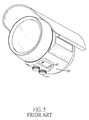
- a conventional adjusting assembly for a lens of a camera comprises a housing 50, a base 60, a driving ring 80, an adjusting rod 70, a retaining ring 90, and an O ring 91.
- the housing 50 is used for storing a camera module of the camera.
- the base 60 is fastened to a bottom of the housing 50.
- the driving ring 80 is securely mounted around the lens and has a toothed portion.
- the adjusting rod 70 is rotatably mounted through the base 60 and has an operating end 71 and a toothed end 72.
- the operating end 71 protrudes out of the housing 50.
- the toothed end 72 protrudes inside the housing 50 and engages with the toothed portion of the driving ring 80.
- the retaining ring 90 is securely mounted around the adjusting rod 70 and is held between the housing 50 and the base 60.
- the O ring 91 is mounted around the operating end 71 of the adjusting rod 70 and is held between the operating end 71 and the base
- a user can hold the operating end 71 of the adjusting rod 70 to turn the adjusting rod 70.
- the driving ring 80 and the lens are turned as well, and the lens can be adjusted without disassembling the housing 50 apart.
- the base 60 is helpful in stabilizing the adjusting rod 70, such that the adjusting rod 70 can rotate relative to the housing 50 without displacement or tilt.
- the retaining ring 90 prevents the adjusting rod 70 from dropping out of the housing 50.
- the main objective of the present invention is to provide an adjusting assembly for a lens of a camera.
- the adjusting assembly has a hollow housing with a mounting portion, at least one driving ring mounted around the lens, at least one turning rod mounted through the mounting portion and engaging with the at least one driving ring, and at least one limiting ring.
- the at least one limiting ring is embedded in the mounting portion of the housing and prevents the at least one turning rod from dropping out of the housing.
- the mounting portion is integrally formed on the housing and has an enlarged thickness that allows the at least one turning rod to be stably mounted on the housing.
- the at least one turning rod is embedded in the housing, such that appearance of the housing is smooth and pleasing.
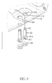
- an adjusting assembly for a lens of a camera comprises a housing 1, a cover 21, at least one driving ring 40, at least one turning rod 30, at least one limiting ring 33, and at least one O ring 34.
- the housing 1 is hollow and has a mounting portion 11, at least one through hole 12, at least one internal wall, at least one flange 13, and an opening 22.
- the mounting portion 11 is integrally formed on the housing 1.
- a thickness of the housing 1 is enlarged at the mounting portion 11.
- the at least one through hole 12 is formed through the mounting portion 11.
- Each of the at least one internal wall of the housing 1 is defined around a corresponding one of the at least one through hole 12 of the housing 1.
- Each of the at least one flange 13 of the housing 1 is formed on and around a corresponding one of the at least one internal wall of the housing 1.
- the opening 22 is formed through the housing 1 and corresponds in position to a memory card module 23 of the camera.
- the cover 21 is detachably mounted on the housing 1 and selectively covers the opening 22 of the housing 1. By detaching the cover 21 from the housing 1, a memory card can be inserted into or drawn out of the memory card module 23 without disassembling the housing 1 apart.
- the housing 1 is formed by attaching a front housing 1 and a rear housing 20.
- the mounting portion 11 and the at least one through hole 12 are formed on the front housing 1.
- the opening 22 is formed through the rear housing 1.
- the cover 21 is detachably mounted on the rear housing 20.
- the at least one driving ring 40 is securely mounted around the lens of the camera and has a toothed portion 41.
- the at least one turning rod 30 is rotatably mounted through the at least one through hole 12 of the housing 1.
- Each of the at least one turning rod 30 has an operating end 31, a slot 311, a flange 312, and a toothed end 32.
- the operating end 31 protrudes in a corresponding one of the at least one through hole 12 of the housing 1 and has an end surface.
- the slot 311 is formed in the end surface of the operating end 31.
- the flange 312 of the turning rod 30 is formed around the operating end 31 and is disposed in the corresponding through hole 12.
- the toothed end 32 protrudes inside the housing 1 and engages with the toothed portion 41 of a corresponding one of the at least one driving ring 40.
- the at least one limiting ring 33 is embedded in the at least one through hole 12 of the housing 1, such that the flange 312 of each of the at least one turning rod 30 is disposed between a corresponding one of the at least one flange 13 of the housing 1 and a corresponding one of the at least one limiting ring 33.
- Each of the at least one limiting ring 33 has an inner end surface and an outer end surface. The inner end surface of the limiting ring 33 abuts the flange 312 of a corresponding one of the at least one turning rod 30.
- the outer end surface of the limiting ring 33 is flush with an outer surface of the mounting portion 11 of the housing 1.
- Each of the at least one O ring 34 is mounted around the operating end 31 of a corresponding one of the at least one turning rod 30 and is held between the flange 312 of the corresponding turning rod 30 and a corresponding one of the at least one flange 13 of the housing 1. With the at least one O ring 34 mounted in the at least one through hole 12 of the housing 1, moisture does not permeate into the housing 1 through the at least one through hole 12.
- the turning rod 30 can be turned by tools, such as a flat-blade screwdriver or the like.
- tools such as a flat-blade screwdriver or the like.
- the at least one driving ring 40 and the lens are turned as well, such that focus and/or diaphragm of the lens can be adjusted without disassembling the housing 1 apart.
- the adjusting assembly for the lens of the camera as described has the following advantages.
- the mounting portion 11 that is integrally formed on the housing 1 and has the enlarged thickness allows the at least one turning rod 30 to be stably mounted on the housing 1. No base needs to be additionally mounted on the housing 1. Moreover, with the operating end 31 of the at least one turning rod 30 mounted in the at least one through hole 12 of the housing 1, appearance of the housing 1 is smooth and pleasing.
Landscapes
- Physics & Mathematics (AREA)
- General Physics & Mathematics (AREA)
- Engineering & Computer Science (AREA)
- Multimedia (AREA)
- Signal Processing (AREA)
- Optics & Photonics (AREA)
- Lens Barrels (AREA)
- Studio Devices (AREA)
Applications Claiming Priority (1)
| Application Number | Priority Date | Filing Date | Title |
|---|---|---|---|
| TW102209467U TWM464697U (zh) | 2013-05-22 | 2013-05-22 | 攝影機調整組件 |
Publications (2)
| Publication Number | Publication Date |
|---|---|
| EP2806300A2 true EP2806300A2 (de) | 2014-11-26 |
| EP2806300A3 EP2806300A3 (de) | 2015-03-04 |
Family
ID=49991611
Family Applications (1)
| Application Number | Title | Priority Date | Filing Date |
|---|---|---|---|
| EP14155449.3A Withdrawn EP2806300A3 (de) | 2013-05-22 | 2014-02-17 | Nachstellvorrichtung für eine Linse einer Kamera |
Country Status (3)
| Country | Link |
|---|---|
| US (1) | US9057818B2 (de) |
| EP (1) | EP2806300A3 (de) |
| TW (1) | TWM464697U (de) |
Families Citing this family (8)
| Publication number | Priority date | Publication date | Assignee | Title |
|---|---|---|---|---|
| US9674450B2 (en) * | 2014-03-31 | 2017-06-06 | Avigilon Corporation | Security camera with adjustable lens aiming mechanism |
| EP3468165B1 (de) * | 2016-03-28 | 2023-12-20 | Ningbo Sunny Opotech Co., Ltd. | Kameramodul und geformte lichtempfindliche anordnung sowie herstellungsverfahren dafür und elektronische vorrichtung |
| US10320832B2 (en) | 2016-12-09 | 2019-06-11 | Sap Se | Attack protection for WebRTC providers |
| USD866637S1 (en) * | 2018-05-29 | 2019-11-12 | Home Tech LLC | Spotlight camera |
| EP3828846B1 (de) * | 2019-11-26 | 2022-07-13 | Axis AB | Kameravorrichtung |
| JP1667021S (de) * | 2020-02-10 | 2020-08-31 | ||
| USD983434S1 (en) * | 2021-12-27 | 2023-04-11 | eNet Innotech (Guangzhou) Limited | Solar lamp |
| USD1110564S1 (en) * | 2024-06-10 | 2026-01-27 | E. Mishan & Sons, Inc. | Security light |
Family Cites Families (10)
| Publication number | Priority date | Publication date | Assignee | Title |
|---|---|---|---|---|
| US2655847A (en) * | 1948-04-15 | 1953-10-20 | Argus Cameras Inc | Automatic film winding and shutter tensioning control camera mechanism |
| US2994258A (en) * | 1957-09-19 | 1961-08-01 | Leitz Ernst Gmbh | Focusing mount for photographic and cinematographic objectives |
| US3566765A (en) * | 1967-12-31 | 1971-03-02 | Shima Kogaku Kk | A device for continuously altering the focal length of photographic lenses |
| US3988749A (en) * | 1972-09-20 | 1976-10-26 | Fritz Victor Hasselblad | Device for automatic diaphragm setting in photographic cameras |
| US4087327A (en) * | 1976-04-12 | 1978-05-02 | Monsanto Company | Mammalion cell culture process |
| US5941669A (en) * | 1998-06-18 | 1999-08-24 | Southco, Inc. | Jack-out captivated screw |
| TWM311049U (en) * | 2006-09-26 | 2007-05-01 | Camdeor Technology Co Ltd | Adjustment apparatus of camera lens distance and focal length for the automatic diaphragm of a monitoring camera |
| US8061947B2 (en) * | 2009-04-16 | 2011-11-22 | GM Global Technology Operations LLC | Fastener retention system |
| US20110234889A1 (en) * | 2010-03-26 | 2011-09-29 | Cwell Vision Co., Ltd. | Monitoring camera |
| US8537220B2 (en) * | 2010-11-11 | 2013-09-17 | Kt&C Co., Ltd | Surveillance camera having lens controller waterproofing member |
-
2013
- 2013-05-22 TW TW102209467U patent/TWM464697U/zh not_active IP Right Cessation
-
2014
- 2014-02-13 US US14/179,851 patent/US9057818B2/en not_active Expired - Fee Related
- 2014-02-17 EP EP14155449.3A patent/EP2806300A3/de not_active Withdrawn
Non-Patent Citations (1)
| Title |
|---|
| None |
Also Published As
| Publication number | Publication date |
|---|---|
| EP2806300A3 (de) | 2015-03-04 |
| US20140347754A1 (en) | 2014-11-27 |
| US9057818B2 (en) | 2015-06-16 |
| TWM464697U (zh) | 2013-11-01 |
Similar Documents
| Publication | Publication Date | Title |
|---|---|---|
| EP2806300A2 (de) | Nachstellvorrichtung für eine Linse einer Kamera | |
| EP3092527B1 (de) | Kameragehäuse für eine quaderförmige kamera | |
| USD606105S1 (en) | Surveillance camera | |
| US9022673B2 (en) | Device support and trigger apparatus | |
| US9772541B2 (en) | Adjusting seat and photographing device using the same | |
| US9031400B2 (en) | Camera with hot shoe unit | |
| US20140044427A1 (en) | Photographic device | |
| JP2013033234A (ja) | 筐体構造及び撮像装置 | |
| US20160185296A1 (en) | Vehicle black box mountable on rear-view mirror support | |
| JP5389760B2 (ja) | 監視カメラ | |
| KR200403448Y1 (ko) | 감시카메라장치 | |
| USD561224S1 (en) | Electronic camera | |
| KR200398599Y1 (ko) | 파노라마 촬영용 로테이터 | |
| JP2020162044A (ja) | インターホン機器 | |
| JP2010286733A (ja) | 露光条件切替ユニットおよびカメラユニット | |
| KR200430380Y1 (ko) | 각도조절 기능을 갖는 차량용 후방 감시카메라 | |
| KR100731200B1 (ko) | 감시용 카메라 | |
| JP6862240B2 (ja) | インターホン機器 | |
| KR20050090781A (ko) | 영상촬영장치의 전면 케이스 | |
| JP2024114459A (ja) | インターホン機器 | |
| JP2020162043A (ja) | インターホン機器 | |
| JP2004077980A (ja) | カメラのグリップ部品取り付け構造 | |
| JP2007201736A (ja) | 発音可能なカメラ | |
| JP3113214U (ja) | ストロボのカメラ取り付け構造 | |
| KR200419707Y1 (ko) | 감시용 카메라 |
Legal Events
| Date | Code | Title | Description |
|---|---|---|---|
| PUAI | Public reference made under article 153(3) epc to a published international application that has entered the european phase |
Free format text: ORIGINAL CODE: 0009012 |
|
| 17P | Request for examination filed |
Effective date: 20140217 |
|
| AK | Designated contracting states |
Kind code of ref document: A2 Designated state(s): AL AT BE BG CH CY CZ DE DK EE ES FI FR GB GR HR HU IE IS IT LI LT LU LV MC MK MT NL NO PL PT RO RS SE SI SK SM TR |
|
| AX | Request for extension of the european patent |
Extension state: BA ME |
|
| PUAL | Search report despatched |
Free format text: ORIGINAL CODE: 0009013 |
|
| AK | Designated contracting states |
Kind code of ref document: A3 Designated state(s): AL AT BE BG CH CY CZ DE DK EE ES FI FR GB GR HR HU IE IS IT LI LT LU LV MC MK MT NL NO PL PT RO RS SE SI SK SM TR |
|
| AX | Request for extension of the european patent |
Extension state: BA ME |
|
| RIC1 | Information provided on ipc code assigned before grant |
Ipc: G03B 17/02 20060101ALN20150126BHEP Ipc: G08B 13/196 20060101ALN20150126BHEP Ipc: H04N 5/225 20060101ALN20150126BHEP Ipc: G02B 7/04 20060101AFI20150126BHEP |
|
| STAA | Information on the status of an ep patent application or granted ep patent |
Free format text: STATUS: THE APPLICATION IS DEEMED TO BE WITHDRAWN |
|
| 18D | Application deemed to be withdrawn |
Effective date: 20150905 |