EP2806317A1 - Procédé et circuit destinés à l'activation et au paramétrage d'un dispositif électrique - Google Patents
Procédé et circuit destinés à l'activation et au paramétrage d'un dispositif électrique Download PDFInfo
- Publication number
- EP2806317A1 EP2806317A1 EP20140169172 EP14169172A EP2806317A1 EP 2806317 A1 EP2806317 A1 EP 2806317A1 EP 20140169172 EP20140169172 EP 20140169172 EP 14169172 A EP14169172 A EP 14169172A EP 2806317 A1 EP2806317 A1 EP 2806317A1
- Authority
- EP
- European Patent Office
- Prior art keywords
- electrical component
- threshold
- sensor
- time window
- threshold value
- Prior art date
- Legal status (The legal status is an assumption and is not a legal conclusion. Google has not performed a legal analysis and makes no representation as to the accuracy of the status listed.)
- Granted
Links
Images



Classifications
-
- H—ELECTRICITY
- H01—ELECTRIC ELEMENTS
- H01H—ELECTRIC SWITCHES; RELAYS; SELECTORS; EMERGENCY PROTECTIVE DEVICES
- H01H47/00—Circuit arrangements not adapted to a particular application of the relay and designed to obtain desired operating characteristics or to provide energising current
-
- G—PHYSICS
- G05—CONTROLLING; REGULATING
- G05B—CONTROL OR REGULATING SYSTEMS IN GENERAL; FUNCTIONAL ELEMENTS OF SUCH SYSTEMS; MONITORING OR TESTING ARRANGEMENTS FOR SUCH SYSTEMS OR ELEMENTS
- G05B9/00—Safety arrangements
- G05B9/02—Safety arrangements electric
-
- G—PHYSICS
- G05—CONTROLLING; REGULATING
- G05B—CONTROL OR REGULATING SYSTEMS IN GENERAL; FUNCTIONAL ELEMENTS OF SUCH SYSTEMS; MONITORING OR TESTING ARRANGEMENTS FOR SUCH SYSTEMS OR ELEMENTS
- G05B19/00—Program-control systems
- G05B19/02—Program-control systems electric
- G05B19/04—Program control other than numerical control, i.e. in sequence controllers or logic controllers
- G05B19/042—Program control other than numerical control, i.e. in sequence controllers or logic controllers using digital processors
Definitions
- the invention relates to a method and a circuit arrangement for activating and parameterizing an electrical device and to the use of an electrical component for activating an electrical device according to the preamble of the independent claims.
- sensors that have a so-called teach-in button are equipped with a time lock.
- a teach-in pushbutton must first be kept pressed for a certain time, for example three seconds, before the teach-in functionality starts.
- Each-in means doing certain configurations of the sensor, that is, the input of, for example, marginal values, parameters and the like after its completion from outside.
- IO-Link interface there were sensors that allow parameterization via a so-called IO-Link interface. Some of these sensors have a local parameterization option in addition to the IO interface, for example a potentiometer.
- IO-Link interface offers the option of assigning a switching threshold directly as a value to a sensor, for example.
- a "Teach-In" via the IO-Link interface is also possible. If, in addition to an IO-Link interface, such a sensor now also has a potentiometer, for example, in order to set switching thresholds, this can lead to synchronization problems of both setting options.
- a new switching threshold is transmitted via the IO-Link interface and at the same time the position of a potentiometer or turntable or even a linear actuator is maintained unchanged, the switching threshold is transmitted via data transfer via the IO-Link interface or a successful IO after transferring the switching threshold - Link teach-in process, the position of the potentiometer or the rotary actuator no longer corresponds to the switching threshold.
- the linear actuator, turntable or the potentiometer can no longer define the switching point.
- the invention is based on the object, an electrical device, such as a sensor of the type described above educate so that an effective manipulation protection is given. Tamper protection is understood to mean protection against unintentional actuation of the electrical component of such a sensor. In addition, a synchronization between a setting of a value by means of the electrical component and a parameterization, for example by means of IO-Link is to be made possible.
- This object is achieved by a method and a circuit arrangement for activating an electrical device of the aforementioned type the features of independent claims 1 and 5 solved.
- the object is also achieved by the use of an electrical component whose values can be changed by, for example, turning or shifting in order to activate such an electrical device.
- the basic idea of the invention is to use an already existing electrical component with an analog or binary output signal whose values can be changed by manipulation, for example turning, shifting, touching, pressing and the like, as a possibility for activating an electrical device.
- a first and a second threshold are given, which can be achieved, for example, by turning or moving or pressing, touching and the like of the electrical component.
- a time window starts within which the second threshold must be reached. If the second threshold is reached within the time window, it is assumed that an activation should take place and an activation signal is output.
- the adjustable electrical component is thus not only used, for example, for setting values of the electrical device, but also for activation and, furthermore, as described below, also for parameterization. If the second switching threshold is not reached within the predefinable time window by manipulation of the electrical component, the activation process is terminated.
- the time window is advantageously realized by means of a timer circuit.
- a first signal for example a light signal
- a second signal is output within the predetermined time window.
- the method according to the invention can also be used for parameterizing an electrical device.
- an end parameterization or (operating) mode setting of the electrical device for example a sensor, can be achieved.
- an electrical component whose values are expediently mechanically changed by rotation or displacement or by pressing, touching, etc., so for example a potentiometer, which changes its resistance value by turning or shifting, or a rotary or linear actuator, by turning or Shifting allows different switching states, has the advantage that not only an activation, but also a parameterization or a mode setting of the electrical device having, for example, a sensor element, even after completion, so for example in the potted state of the electrical device is still possible.
- an electrical component is used anyway for setting, for example a switching value or the like is present. An additional hardware effort is not required.
- the electrical device may be, for example, a sensor.
- the senor may be a proximity sensor or a distance sensor, that is to say a sensor which reacts to an approach of an object or which determines the distance of an object.
- the sensor may also be a temperature sensor, a pressure sensor or a humidity sensor or another sensor for detecting physical quantities.
- a circuit arrangement 40 shown in FIG. 1 , For example, has an IO-link interface 11, via which, for example, parameter data in a memory 44 of the circuit arrangement 40, which in turn is part of an electrical device 50, can be stored.
- the electrical device 50 further includes, for example, a sensor element 10, which outputs a signal when the sensor - as exemplified - is a proximity sensor and a target 20 is arranged in front of it.
- a proximity sensor which outputs a signal when the sensor - as exemplified - is a proximity sensor and a target 20 is arranged in front of it.
- the invention will be described below in connection with such a proximity sensor. However, it should be emphasized that the invention is not limited to a proximity sensor, but purely in principle with any sensors, such as temperature sensors, pressure sensors or other virtually any sensors that detect physical variables, can be used.
- the circuit arrangement 40 serves for the evaluation of the sensor signals as well as the control of the sensor element 10.
- the electrical device 50 furthermore has an electrical component 30 whose values can be changed, for example, by turning or shifting, pressing, touching or other manipulations.
- This device 30 may be, for example, a potentiometer which is adjustable from outside, which is to be symbolized schematically by the line 32.
- the electronic circuit arrangement 40 also has a timer circuit 41, which will be discussed in more detail below, as well as a light-emitting diode 42.
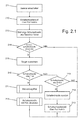
- FIG. 2 and FIG. 3 An embodiment of a method according to the invention will now be explained with reference to the setting of a switching threshold of the electrical device 50.
- step 211 the electrical device 50 is turned on or the supply voltage is turned on.
- step 212 initially a switching threshold definition via the electrical component (potentiometer) 30 is inactive.
- step 213 therefore, the previous switching threshold is read from the memory 44.
- step 214 it is queried whether a switching threshold adjustment should take place. If this is the case, first, in a step 215, a switching distance with respect to the target 20 is readjusted.
- the switching threshold can be readjusted via the electrical component 30, in the present case a potentiometer, or otherwise, for example due to a data transmission by means of the IO-Link interface 11. Otherwise, the previous switching threshold is maintained.
- step 216 it is queried whether a switching threshold definition should take place via the electrical component 30.
- the user first performs an activation process for the application of the electrical component 30 for switching threshold definition in step 217.
- the electrical device 30 may be used in step 218 to define the switching threshold of the sensor element 10.
- a switching threshold is otherwise supplied, for example due to data transmission by means of the IO-Link interface 11 in step 21A (in FIG. 3 this area is designated by reference numeral 305), whereupon in step 21 B the switching threshold definition via the potentiometer 30 is deactivated.
- the method steps described above can be realized by a threshold value device, which is designed as a circuit, for example, or else as a computer program in a corresponding computer component.
- Figure 2.2 shows the method for activating the electrical component 30 for switching threshold definition of the sensor element 10.
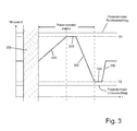
- the electrical component in the form of a rotary potentiometer 30 is rotated in step 221 toward a first threshold S1 (In FIG. 3 this is indicated by reference numeral 310).
- step 222 it is checked if the threshold S1 is reached. If it is determined in step 222 that the threshold S1 has been reached (in FIG. 3 if this is indicated by reference numeral 315), a signal (e.g. a light signal) is output, step 223.
- the process is indicated by an example flashing (yellow) LED 42, which signals the user that the switching threshold definition via the potentiometer 30 is now ready and waiting for further operation.
- step 224 the user has a predefinable time window available to the measurement in step 224, the timer is reset. Further operation is the further turning or turning back of the potentiometer in step 225 (in FIG. 3 this is designated by reference numeral 320).
- step 226 it is checked whether a second threshold S2 has been reached by turning back the potentiometer. If this is not the case, it is checked in step 229 if there is a time-out, ie it is checked whether the time window provided for reaching the threshold S2 has expired. If the time window has expired without reaching the second threshold S2, the switching threshold definition of the electrical component 30 is deactivated again.
- step 226 If, on the other hand, it is detected in step 226 that the second threshold S2 has been reached within the time window, the electrical component 30 is activated comprehensively for switching threshold determination (step 227). This operating state is also signaled by a light signal of the light-emitting diode 42 (step 228). The sensor is for adjusting the switching threshold by means of the electrical component, that is the present potentiometer 30, ready.
- FIG. 2.3 shows the method for setting the switching threshold, the sensor is ready to set the switching threshold with the potentiometer.
- the potentiometer is slowly turned back (step 231), in FIG. 3 designated 330 until a switching threshold is reached (step 232).
- the timing of the timer 41 is continuously reset (step 233). If, however, the switching threshold is reached and the potentiometer is no longer rotated, the timing of the timer 41 begins. Namely, the potentiometer is activated and the potentiometer for a certain period of time that is adjustable and can be predetermined and, for example, 1 to 5 minutes, no longer used , the potentiometer is automatically deactivated (step 234).
- the value of the potentiometer is read out and stored as a new switching threshold in the memory 44 of the circuit 40 (step 235).
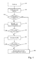
- the electrical component 30, here the potentiometer, but can also be used to parameterize the electrical device 50 and to determine their operating mode, for example, whether the electrical device 50 in a PNP / PP / NPN mode (PP push-pull ) or in an NC or NO mode. This will be described below in connection with FIG. 4 described.
- a power-up that is a voltage supply of the sensor 10.
- the movements of the electrical component 30 are read and checked in step 430, for example, whether the electrical component 30 within a predetermined or predetermined (from pre-determined) time span (in the example 5s) has been rotated or pushed five times above or below a respectively predefinable or predetermined threshold.
- step 450 it is checked whether the potentiometer has not been moved, for example, for five seconds. If this is not the case, the system returns to step 440. If this is the case, however, an adjustment of the NO / NC mode follows in step 460.
- step 470 it is again checked whether the potentiometer has not been moved, for example, for five seconds. If this is the case, the set sensor function is adopted in step 480 and the setting option is disabled at the same time. If not, the process returns to step 460 where the (operating) mode is set.
- These setting operations may be associated, for example, with a blinking of the light emitting diode 42 or a signal of another signaling device, so that an operator can recognize the setting operations.
- the advantage of the above-described method and the circuit arrangement and the use of the potentiometer or more generally an electrical component for activation and for parameterization and definition the operating mode is that even finished sensors can be activated from the outside, with no additional switches or additional hardware, such as a push button, must be provided, but rather an electrical component whose values can be changed by turning or moving and which actually for adjustment For example, a switching distance or sensor-specific values is used, can be used to activate the electrical device 50 or to parameterize them or to set their operating mode.
Landscapes
- Physics & Mathematics (AREA)
- General Physics & Mathematics (AREA)
- Engineering & Computer Science (AREA)
- Automation & Control Theory (AREA)
- Electronic Switches (AREA)
Applications Claiming Priority (1)
| Application Number | Priority Date | Filing Date | Title |
|---|---|---|---|
| DE201310008807 DE102013008807A1 (de) | 2013-05-24 | 2013-05-24 | Verfahren und Schaltungsanordnung zur Aktivierung und Parametrisierung einer elektrischen Einrichtung |
Publications (2)
| Publication Number | Publication Date |
|---|---|
| EP2806317A1 true EP2806317A1 (fr) | 2014-11-26 |
| EP2806317B1 EP2806317B1 (fr) | 2018-11-14 |
Family
ID=50897355
Family Applications (1)
| Application Number | Title | Priority Date | Filing Date |
|---|---|---|---|
| EP14169172.5A Active EP2806317B1 (fr) | 2013-05-24 | 2014-05-20 | Procédé et dispositif électrique avec un circuit destiné à l'activation et au paramétrage du dispositif électrique |
Country Status (3)
| Country | Link |
|---|---|
| US (1) | US10062532B2 (fr) |
| EP (1) | EP2806317B1 (fr) |
| DE (1) | DE102013008807A1 (fr) |
Families Citing this family (2)
| Publication number | Priority date | Publication date | Assignee | Title |
|---|---|---|---|---|
| DE102015216898B4 (de) * | 2015-09-03 | 2017-08-24 | Di-Soric Gmbh & Co. Kg | Sensoreinrichtung zur Überwachung eines Sensorbereichs und Verfahren zum Umschalten zwischen zwei Betriebsmodi |
| JP6610286B2 (ja) * | 2016-01-22 | 2019-11-27 | オムロン株式会社 | 近接スイッチ |
Citations (1)
| Publication number | Priority date | Publication date | Assignee | Title |
|---|---|---|---|---|
| EP2560208A1 (fr) * | 2011-08-16 | 2013-02-20 | Balluff GmbH | Capteur optoélectronique |
Family Cites Families (10)
| Publication number | Priority date | Publication date | Assignee | Title |
|---|---|---|---|---|
| US6452617B1 (en) * | 2000-01-10 | 2002-09-17 | International Business Machines Corporation | Adjusting a click time threshold for a graphical user interface |
| DE10035592A1 (de) * | 2000-07-21 | 2002-01-31 | Ego Elektro Geraetebau Gmbh | Anordnung zur Steuerung von elektrisch ansteuerbaren Geräten, insbesondere Elektrowärmegeräten |
| DE202004020673U1 (de) * | 2003-10-08 | 2005-11-03 | Philipp, Harald, Southampton | Berührungs-sensitives Bedienfeld |
| DE102004020827A1 (de) * | 2004-04-28 | 2005-11-24 | Preh Gmbh | Drehsteller |
| US8049731B2 (en) * | 2005-07-29 | 2011-11-01 | Interlink Electronics, Inc. | System and method for implementing a control function via a sensor having a touch sensitive control input surface |
| DE102010007455B4 (de) * | 2010-02-10 | 2024-06-27 | Microchip Technology Germany Gmbh | System und Verfahren zum berührungslosen Erfassen und Erkennen von Gesten in einem dreidimensionalen Raum |
| US8412361B1 (en) * | 2010-04-05 | 2013-04-02 | Charles A. Reynolds | Remote identification and verification of a function prior to use thereof |
| DE102011077170A1 (de) * | 2011-06-08 | 2012-12-13 | BSH Bosch und Siemens Hausgeräte GmbH | Bedien- und Anzeigeeinrichtung und Haushaltsgerät |
| DE102011086320A1 (de) * | 2011-11-14 | 2013-05-16 | Lufthansa Technik Ag | Möbelstück mit einem elektronischen Schaltelement für ein Verkehrsflugzeug |
| EP2787406A3 (fr) * | 2012-05-16 | 2015-01-21 | Siemens Aktiengesellschaft | Écran tactile avec détection de pression analogique pour une installation technique industrielle |
-
2013
- 2013-05-24 DE DE201310008807 patent/DE102013008807A1/de not_active Withdrawn
-
2014
- 2014-05-20 EP EP14169172.5A patent/EP2806317B1/fr active Active
- 2014-05-21 US US14/283,495 patent/US10062532B2/en active Active
Patent Citations (1)
| Publication number | Priority date | Publication date | Assignee | Title |
|---|---|---|---|---|
| EP2560208A1 (fr) * | 2011-08-16 | 2013-02-20 | Balluff GmbH | Capteur optoélectronique |
Also Published As
| Publication number | Publication date |
|---|---|
| DE102013008807A1 (de) | 2014-11-27 |
| EP2806317B1 (fr) | 2018-11-14 |
| US20140346895A1 (en) | 2014-11-27 |
| US10062532B2 (en) | 2018-08-28 |
Similar Documents
| Publication | Publication Date | Title |
|---|---|---|
| EP0876647B1 (fr) | Interface graphique d'exploitation pour la programmation de commandes programmables | |
| DE19912446C1 (de) | Einrichtung zum Einstellen von Betriebsgrößen in mehreren programmierbaren integrierten Schaltungen, insbesondere enthaltend jeweils einen Hallgenerator | |
| WO2001069181A1 (fr) | Dispositif de detection de position | |
| DE102013112488A1 (de) | Sicherheitssteuerung mit konfigurierbaren Eingängen | |
| DE102007006422A1 (de) | Verfahren zum Betreiben von Maschinen mit anpassbaren Bewegungsprofilen | |
| EP2550740B1 (fr) | Élément électronique pour un dispositif de capteur, dispositif de capteur et procédé de configuration d'un dispositif de capteur | |
| DE102013002830A1 (de) | Manuell bedienbare Eingabevorrichtung mit Code-Erfassung | |
| EP1932007B1 (fr) | Dispositif et procede d'evaluation a securite integree d'un transmetteur de position, en particulier d'un potentiometre | |
| EP2806317B1 (fr) | Procédé et dispositif électrique avec un circuit destiné à l'activation et au paramétrage du dispositif électrique | |
| EP1845501B1 (fr) | Système de mesure doté d'au moins un conducteur de détection | |
| DE102008024398B4 (de) | Näherungsschalter und Verfahren zum Betreiben eines Näherungsschalters | |
| EP0519089B1 (fr) | Introduction de paramètres de service dans un commutateur de proximité prêt à servir | |
| DE202008002844U1 (de) | Programmierbarer Positionssensor | |
| EP1203933A1 (fr) | Dispositif capteur pour la mesure d'au moins une grandeur | |
| DE102007026457B4 (de) | Vorrichtung zur Inbetriebnahme eines Feldbusteilnehmersystems sowie Inbetriebnahmeverfahren | |
| DE102014106661A1 (de) | Schalterbetätigungseinrichtung, mobiles Gerät und Verfahren zum Betätigen eines Schalters durch eine nicht-taktile Translationsgeste | |
| DE3530678A1 (de) | Verfahren und vorrichtung zur speicherprogrammierten steuerung bewegbarer vorrichtungen | |
| DE102008057725B4 (de) | System zum Abgleichen, Einstellen und/oder Programmieren von elektronischen Geräten, insbesondere Messgeräten, welche Sensoren aufweisen, sowie Schaltungsanordnung zum Abgleichen, Einstellen oder Programmieren von elektronischen Elementen, wie digitalen Potentiometern | |
| DE202014101601U1 (de) | Steckverbinder mit Bedienelement | |
| DE102010004638B3 (de) | Potentiometer mit Hauptstellbereich und Sonderfunktionsbereich und Steuerung / Auswertung hierzu | |
| DE102016014308A1 (de) | Sicherheitseingangssignale erzeugende Schaltvorrichtung und numerisches Steuersystem | |
| EP2296077B1 (fr) | Procédé de réglage de paramètres de fonctionnement d'un capteur et capteur pour une grandeur de mesure physique | |
| DE102007026512A1 (de) | Schaltgerät, System und Verfahren | |
| DE102005047337B4 (de) | Verfahren zur Einstellung von Helligkeitsschwellwerten bei Präsenzmeldern | |
| DE20308840U1 (de) | Steuereinrichtung |
Legal Events
| Date | Code | Title | Description |
|---|---|---|---|
| PUAI | Public reference made under article 153(3) epc to a published international application that has entered the european phase |
Free format text: ORIGINAL CODE: 0009012 |
|
| 17P | Request for examination filed |
Effective date: 20140520 |
|
| AK | Designated contracting states |
Kind code of ref document: A1 Designated state(s): AL AT BE BG CH CY CZ DE DK EE ES FI FR GB GR HR HU IE IS IT LI LT LU LV MC MK MT NL NO PL PT RO RS SE SI SK SM TR |
|
| AX | Request for extension of the european patent |
Extension state: BA ME |
|
| R17P | Request for examination filed (corrected) |
Effective date: 20150401 |
|
| RBV | Designated contracting states (corrected) |
Designated state(s): AL AT BE BG CH CY CZ DE DK EE ES FI FR GB GR HR HU IE IS IT LI LT LU LV MC MK MT NL NO PL PT RO RS SE SI SK SM TR |
|
| STAA | Information on the status of an ep patent application or granted ep patent |
Free format text: STATUS: EXAMINATION IS IN PROGRESS |
|
| 17Q | First examination report despatched |
Effective date: 20180212 |
|
| GRAP | Despatch of communication of intention to grant a patent |
Free format text: ORIGINAL CODE: EPIDOSNIGR1 |
|
| STAA | Information on the status of an ep patent application or granted ep patent |
Free format text: STATUS: GRANT OF PATENT IS INTENDED |
|
| INTG | Intention to grant announced |
Effective date: 20180613 |
|
| GRAS | Grant fee paid |
Free format text: ORIGINAL CODE: EPIDOSNIGR3 |
|
| GRAA | (expected) grant |
Free format text: ORIGINAL CODE: 0009210 |
|
| STAA | Information on the status of an ep patent application or granted ep patent |
Free format text: STATUS: THE PATENT HAS BEEN GRANTED |
|
| AK | Designated contracting states |
Kind code of ref document: B1 Designated state(s): AL AT BE BG CH CY CZ DE DK EE ES FI FR GB GR HR HU IE IS IT LI LT LU LV MC MK MT NL NO PL PT RO RS SE SI SK SM TR |
|
| REG | Reference to a national code |
Ref country code: CH Ref legal event code: EP Ref country code: AT Ref legal event code: REF Ref document number: 1065556 Country of ref document: AT Kind code of ref document: T Effective date: 20181115 |
|
| REG | Reference to a national code |
Ref country code: DE Ref legal event code: R096 Ref document number: 502014010033 Country of ref document: DE |
|
| REG | Reference to a national code |
Ref country code: IE Ref legal event code: FG4D Free format text: LANGUAGE OF EP DOCUMENT: GERMAN |
|
| REG | Reference to a national code |
Ref country code: NL Ref legal event code: MP Effective date: 20181114 |
|
| REG | Reference to a national code |
Ref country code: LT Ref legal event code: MG4D |
|
| PG25 | Lapsed in a contracting state [announced via postgrant information from national office to epo] |
Ref country code: ES Free format text: LAPSE BECAUSE OF FAILURE TO SUBMIT A TRANSLATION OF THE DESCRIPTION OR TO PAY THE FEE WITHIN THE PRESCRIBED TIME-LIMIT Effective date: 20181114 Ref country code: NO Free format text: LAPSE BECAUSE OF FAILURE TO SUBMIT A TRANSLATION OF THE DESCRIPTION OR TO PAY THE FEE WITHIN THE PRESCRIBED TIME-LIMIT Effective date: 20190214 Ref country code: BG Free format text: LAPSE BECAUSE OF FAILURE TO SUBMIT A TRANSLATION OF THE DESCRIPTION OR TO PAY THE FEE WITHIN THE PRESCRIBED TIME-LIMIT Effective date: 20190214 Ref country code: IS Free format text: LAPSE BECAUSE OF FAILURE TO SUBMIT A TRANSLATION OF THE DESCRIPTION OR TO PAY THE FEE WITHIN THE PRESCRIBED TIME-LIMIT Effective date: 20190314 Ref country code: FI Free format text: LAPSE BECAUSE OF FAILURE TO SUBMIT A TRANSLATION OF THE DESCRIPTION OR TO PAY THE FEE WITHIN THE PRESCRIBED TIME-LIMIT Effective date: 20181114 Ref country code: LT Free format text: LAPSE BECAUSE OF FAILURE TO SUBMIT A TRANSLATION OF THE DESCRIPTION OR TO PAY THE FEE WITHIN THE PRESCRIBED TIME-LIMIT Effective date: 20181114 Ref country code: LV Free format text: LAPSE BECAUSE OF FAILURE TO SUBMIT A TRANSLATION OF THE DESCRIPTION OR TO PAY THE FEE WITHIN THE PRESCRIBED TIME-LIMIT Effective date: 20181114 Ref country code: HR Free format text: LAPSE BECAUSE OF FAILURE TO SUBMIT A TRANSLATION OF THE DESCRIPTION OR TO PAY THE FEE WITHIN THE PRESCRIBED TIME-LIMIT Effective date: 20181114 |
|
| PG25 | Lapsed in a contracting state [announced via postgrant information from national office to epo] |
Ref country code: SE Free format text: LAPSE BECAUSE OF FAILURE TO SUBMIT A TRANSLATION OF THE DESCRIPTION OR TO PAY THE FEE WITHIN THE PRESCRIBED TIME-LIMIT Effective date: 20181114 Ref country code: NL Free format text: LAPSE BECAUSE OF FAILURE TO SUBMIT A TRANSLATION OF THE DESCRIPTION OR TO PAY THE FEE WITHIN THE PRESCRIBED TIME-LIMIT Effective date: 20181114 Ref country code: RS Free format text: LAPSE BECAUSE OF FAILURE TO SUBMIT A TRANSLATION OF THE DESCRIPTION OR TO PAY THE FEE WITHIN THE PRESCRIBED TIME-LIMIT Effective date: 20181114 Ref country code: AL Free format text: LAPSE BECAUSE OF FAILURE TO SUBMIT A TRANSLATION OF THE DESCRIPTION OR TO PAY THE FEE WITHIN THE PRESCRIBED TIME-LIMIT Effective date: 20181114 Ref country code: PT Free format text: LAPSE BECAUSE OF FAILURE TO SUBMIT A TRANSLATION OF THE DESCRIPTION OR TO PAY THE FEE WITHIN THE PRESCRIBED TIME-LIMIT Effective date: 20190314 Ref country code: GR Free format text: LAPSE BECAUSE OF FAILURE TO SUBMIT A TRANSLATION OF THE DESCRIPTION OR TO PAY THE FEE WITHIN THE PRESCRIBED TIME-LIMIT Effective date: 20190215 |
|
| PG25 | Lapsed in a contracting state [announced via postgrant information from national office to epo] |
Ref country code: PL Free format text: LAPSE BECAUSE OF FAILURE TO SUBMIT A TRANSLATION OF THE DESCRIPTION OR TO PAY THE FEE WITHIN THE PRESCRIBED TIME-LIMIT Effective date: 20181114 Ref country code: CZ Free format text: LAPSE BECAUSE OF FAILURE TO SUBMIT A TRANSLATION OF THE DESCRIPTION OR TO PAY THE FEE WITHIN THE PRESCRIBED TIME-LIMIT Effective date: 20181114 Ref country code: DK Free format text: LAPSE BECAUSE OF FAILURE TO SUBMIT A TRANSLATION OF THE DESCRIPTION OR TO PAY THE FEE WITHIN THE PRESCRIBED TIME-LIMIT Effective date: 20181114 Ref country code: IT Free format text: LAPSE BECAUSE OF FAILURE TO SUBMIT A TRANSLATION OF THE DESCRIPTION OR TO PAY THE FEE WITHIN THE PRESCRIBED TIME-LIMIT Effective date: 20181114 |
|
| REG | Reference to a national code |
Ref country code: DE Ref legal event code: R097 Ref document number: 502014010033 Country of ref document: DE |
|
| PG25 | Lapsed in a contracting state [announced via postgrant information from national office to epo] |
Ref country code: SM Free format text: LAPSE BECAUSE OF FAILURE TO SUBMIT A TRANSLATION OF THE DESCRIPTION OR TO PAY THE FEE WITHIN THE PRESCRIBED TIME-LIMIT Effective date: 20181114 Ref country code: EE Free format text: LAPSE BECAUSE OF FAILURE TO SUBMIT A TRANSLATION OF THE DESCRIPTION OR TO PAY THE FEE WITHIN THE PRESCRIBED TIME-LIMIT Effective date: 20181114 Ref country code: RO Free format text: LAPSE BECAUSE OF FAILURE TO SUBMIT A TRANSLATION OF THE DESCRIPTION OR TO PAY THE FEE WITHIN THE PRESCRIBED TIME-LIMIT Effective date: 20181114 Ref country code: SK Free format text: LAPSE BECAUSE OF FAILURE TO SUBMIT A TRANSLATION OF THE DESCRIPTION OR TO PAY THE FEE WITHIN THE PRESCRIBED TIME-LIMIT Effective date: 20181114 |
|
| PLBE | No opposition filed within time limit |
Free format text: ORIGINAL CODE: 0009261 |
|
| STAA | Information on the status of an ep patent application or granted ep patent |
Free format text: STATUS: NO OPPOSITION FILED WITHIN TIME LIMIT |
|
| 26N | No opposition filed |
Effective date: 20190815 |
|
| PG25 | Lapsed in a contracting state [announced via postgrant information from national office to epo] |
Ref country code: SI Free format text: LAPSE BECAUSE OF FAILURE TO SUBMIT A TRANSLATION OF THE DESCRIPTION OR TO PAY THE FEE WITHIN THE PRESCRIBED TIME-LIMIT Effective date: 20181114 |
|
| REG | Reference to a national code |
Ref country code: CH Ref legal event code: PL |
|
| GBPC | Gb: european patent ceased through non-payment of renewal fee |
Effective date: 20190520 |
|
| PG25 | Lapsed in a contracting state [announced via postgrant information from national office to epo] |
Ref country code: LI Free format text: LAPSE BECAUSE OF NON-PAYMENT OF DUE FEES Effective date: 20190531 Ref country code: MC Free format text: LAPSE BECAUSE OF FAILURE TO SUBMIT A TRANSLATION OF THE DESCRIPTION OR TO PAY THE FEE WITHIN THE PRESCRIBED TIME-LIMIT Effective date: 20181114 Ref country code: CH Free format text: LAPSE BECAUSE OF NON-PAYMENT OF DUE FEES Effective date: 20190531 |
|
| REG | Reference to a national code |
Ref country code: BE Ref legal event code: MM Effective date: 20190531 |
|
| PG25 | Lapsed in a contracting state [announced via postgrant information from national office to epo] |
Ref country code: LU Free format text: LAPSE BECAUSE OF NON-PAYMENT OF DUE FEES Effective date: 20190520 |
|
| PG25 | Lapsed in a contracting state [announced via postgrant information from national office to epo] |
Ref country code: TR Free format text: LAPSE BECAUSE OF FAILURE TO SUBMIT A TRANSLATION OF THE DESCRIPTION OR TO PAY THE FEE WITHIN THE PRESCRIBED TIME-LIMIT Effective date: 20181114 |
|
| PG25 | Lapsed in a contracting state [announced via postgrant information from national office to epo] |
Ref country code: GB Free format text: LAPSE BECAUSE OF NON-PAYMENT OF DUE FEES Effective date: 20190520 Ref country code: IE Free format text: LAPSE BECAUSE OF NON-PAYMENT OF DUE FEES Effective date: 20190520 |
|
| PG25 | Lapsed in a contracting state [announced via postgrant information from national office to epo] |
Ref country code: BE Free format text: LAPSE BECAUSE OF NON-PAYMENT OF DUE FEES Effective date: 20190531 |
|
| PG25 | Lapsed in a contracting state [announced via postgrant information from national office to epo] |
Ref country code: FR Free format text: LAPSE BECAUSE OF NON-PAYMENT OF DUE FEES Effective date: 20190531 |
|
| REG | Reference to a national code |
Ref country code: AT Ref legal event code: MM01 Ref document number: 1065556 Country of ref document: AT Kind code of ref document: T Effective date: 20190520 |
|
| PG25 | Lapsed in a contracting state [announced via postgrant information from national office to epo] |
Ref country code: AT Free format text: LAPSE BECAUSE OF NON-PAYMENT OF DUE FEES Effective date: 20190520 |
|
| PG25 | Lapsed in a contracting state [announced via postgrant information from national office to epo] |
Ref country code: CY Free format text: LAPSE BECAUSE OF FAILURE TO SUBMIT A TRANSLATION OF THE DESCRIPTION OR TO PAY THE FEE WITHIN THE PRESCRIBED TIME-LIMIT Effective date: 20181114 |
|
| PG25 | Lapsed in a contracting state [announced via postgrant information from national office to epo] |
Ref country code: HU Free format text: LAPSE BECAUSE OF FAILURE TO SUBMIT A TRANSLATION OF THE DESCRIPTION OR TO PAY THE FEE WITHIN THE PRESCRIBED TIME-LIMIT; INVALID AB INITIO Effective date: 20140520 Ref country code: MT Free format text: LAPSE BECAUSE OF FAILURE TO SUBMIT A TRANSLATION OF THE DESCRIPTION OR TO PAY THE FEE WITHIN THE PRESCRIBED TIME-LIMIT Effective date: 20181114 |
|
| PG25 | Lapsed in a contracting state [announced via postgrant information from national office to epo] |
Ref country code: MK Free format text: LAPSE BECAUSE OF FAILURE TO SUBMIT A TRANSLATION OF THE DESCRIPTION OR TO PAY THE FEE WITHIN THE PRESCRIBED TIME-LIMIT Effective date: 20181114 |
|
| P01 | Opt-out of the competence of the unified patent court (upc) registered |
Effective date: 20230530 |
|
| PGFP | Annual fee paid to national office [announced via postgrant information from national office to epo] |
Ref country code: DE Payment date: 20260422 Year of fee payment: 13 |