EP2806449A1 - Actionneur d'une bobine pour appareil de commutation à basse et moyenne tension et dispositif de suppression de bobine de défaut d'arc comprenant ledit actionneur de bobine - Google Patents
Actionneur d'une bobine pour appareil de commutation à basse et moyenne tension et dispositif de suppression de bobine de défaut d'arc comprenant ledit actionneur de bobine Download PDFInfo
- Publication number
- EP2806449A1 EP2806449A1 EP13168677.6A EP13168677A EP2806449A1 EP 2806449 A1 EP2806449 A1 EP 2806449A1 EP 13168677 A EP13168677 A EP 13168677A EP 2806449 A1 EP2806449 A1 EP 2806449A1
- Authority
- EP
- European Patent Office
- Prior art keywords
- coil
- unit
- signal
- detection
- coil actuator
- Prior art date
- Legal status (The legal status is an assumption and is not a legal conclusion. Google has not performed a legal analysis and makes no representation as to the accuracy of the status listed.)
- Granted
Links
Images


Classifications
-
- H—ELECTRICITY
- H02—GENERATION; CONVERSION OR DISTRIBUTION OF ELECTRIC POWER
- H02H—EMERGENCY PROTECTIVE CIRCUIT ARRANGEMENTS
- H02H1/00—Details of emergency protective circuit arrangements
- H02H1/0007—Details of emergency protective circuit arrangements concerning the detecting means
- H02H1/0015—Using arc detectors
- H02H1/0023—Using arc detectors sensing non electrical parameters, e.g. by optical, pneumatic, thermal or sonic sensors
-
- H—ELECTRICITY
- H01—ELECTRIC ELEMENTS
- H01H—ELECTRIC SWITCHES; RELAYS; SELECTORS; EMERGENCY PROTECTIVE DEVICES
- H01H83/00—Protective switches, e.g. circuit-breaking switches, or protective relays operated by abnormal electrical conditions otherwise than solely by excess current
- H01H83/20—Protective switches, e.g. circuit-breaking switches, or protective relays operated by abnormal electrical conditions otherwise than solely by excess current operated by excess current as well as by some other abnormal electrical condition
-
- H—ELECTRICITY
- H02—GENERATION; CONVERSION OR DISTRIBUTION OF ELECTRIC POWER
- H02H—EMERGENCY PROTECTIVE CIRCUIT ARRANGEMENTS
- H02H3/00—Emergency protective circuit arrangements for automatic disconnection directly responsive to an undesired change from normal electric working condition with or without subsequent reconnection ; integrated protection
- H02H3/16—Emergency protective circuit arrangements for automatic disconnection directly responsive to an undesired change from normal electric working condition with or without subsequent reconnection ; integrated protection responsive to fault current to earth, frame or mass
-
- H—ELECTRICITY
- H01—ELECTRIC ELEMENTS
- H01H—ELECTRIC SWITCHES; RELAYS; SELECTORS; EMERGENCY PROTECTIVE DEVICES
- H01H83/00—Protective switches, e.g. circuit-breaking switches, or protective relays operated by abnormal electrical conditions otherwise than solely by excess current
- H01H83/20—Protective switches, e.g. circuit-breaking switches, or protective relays operated by abnormal electrical conditions otherwise than solely by excess current operated by excess current as well as by some other abnormal electrical condition
- H01H2083/201—Protective switches, e.g. circuit-breaking switches, or protective relays operated by abnormal electrical conditions otherwise than solely by excess current operated by excess current as well as by some other abnormal electrical condition the other abnormal electrical condition being an arc fault
-
- H—ELECTRICITY
- H01—ELECTRIC ELEMENTS
- H01H—ELECTRIC SWITCHES; RELAYS; SELECTORS; EMERGENCY PROTECTIVE DEVICES
- H01H83/00—Protective switches, e.g. circuit-breaking switches, or protective relays operated by abnormal electrical conditions otherwise than solely by excess current
- H01H83/12—Protective switches, e.g. circuit-breaking switches, or protective relays operated by abnormal electrical conditions otherwise than solely by excess current operated by voltage falling below a predetermined value, e.g. for no-volt protection
-
- H—ELECTRICITY
- H02—GENERATION; CONVERSION OR DISTRIBUTION OF ELECTRIC POWER
- H02H—EMERGENCY PROTECTIVE CIRCUIT ARRANGEMENTS
- H02H3/00—Emergency protective circuit arrangements for automatic disconnection directly responsive to an undesired change from normal electric working condition with or without subsequent reconnection ; integrated protection
- H02H3/16—Emergency protective circuit arrangements for automatic disconnection directly responsive to an undesired change from normal electric working condition with or without subsequent reconnection ; integrated protection responsive to fault current to earth, frame or mass
- H02H3/162—Emergency protective circuit arrangements for automatic disconnection directly responsive to an undesired change from normal electric working condition with or without subsequent reconnection ; integrated protection responsive to fault current to earth, frame or mass for AC systems
Definitions
- the present invention relates to a coil actuator for low and medium voltage switching apparatuses, such as circuit breakers, disconnectors, contactors, reclosers or the like.
- the present invention relates to an arc fault coil suppression device for a low and medium voltage electrical system (such as a switching apparatus, a switchboard, a grid or the like), which comprises said coil actuator.
- a low and medium voltage electrical system such as a switching apparatus, a switchboard, a grid or the like
- the coil actuator and the arc fault coil suppression device of the invention may be conveniently used in low and medium voltage applications.
- low voltage relates to voltages lower than 1 kV AC and 1.5 kV DC while the term “medium voltage” relates to voltages lower than 72 kV AC and 100 kV DC.
- arc faults are phenomena that sometimes occur between phase conductors, phase and neutral conductors or phase and ground conductors of electrical systems.
- known solutions generally provide for tripping a switching apparatus to interrupt the current flow towards the flow (circuit breaking) or divert the current flow towards ground (earth switching).
- tripping commands to the switching apparatus are generated by a control a protection unit associated therewith, which is conveniently provided with an optical input port suitable to receive a light signal from the optical detection means.
- tripping commands to the switching apparatus are provided by a dedicated protection device (arc suppressor) that is specifically designed to interface with the optical detection means and process the optical detection signals therefrom, thus ensuring a faster intervention for suppressing the arc fault.
- a dedicated protection device arc suppressor
- the present invention is aimed at providing an arc fault suppression arrangement that can be conveniently installed in a wide range of electrical systems, even in electrical systems having a relatively low market price.
- Still another object of the present invention is to provide an arc fault suppression arrangement that is relatively easy to install in already existing electrical systems, for retrofitting and upgrading purposes.
- the present invention provides a coil actuator for a low and medium voltage switching apparatus, according to the following claim 1 and the related dependent claims.
- the present invention provides an arc fault coil suppression device, according to the following claim 7 and the related dependent claims.
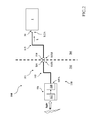
- the present invention relates to a coil actuator 1 for a low and medium voltage switching apparatus.
- the coil actuator 1 is suitable to be operatively positioned in a seat of the coil actuator compartment of the switching apparatus (not shown), so as to be operatively associated with an actuation mechanism of this latter.
- said switching apparatus may be a medium voltage circuit breaker and said actuation mechanism may be the primary command chain of said circuit breaker.
- the coil actuator 1 comprises a casing in which a coil electromagnet 2 is housed, which comprises a coil 2B (preferably a single coil) that is operatively associated with a movable plunger 2A.
- the movable plunger 2A is normally in a rest position and it moves (trip event) when the coil 2B is energized by an excitation current I E , since it is launched by the magnetic force generated by the coil 2B.
- the movable plunger 2A is operatively associated with an actuating spring (not shown), so as to be moved by said actuating spring when an excitation current I E , which normally circulates along the coil 2B, is interrupted.
- the coil 2B in normal conditions, the coil 2B generates a magnetic force that opposes the mechanical force exerted by the actuating spring, which is in a compression state.
- the coil electromagnet 2 trips when the excitation current I E is interrupted and the movable plunger 2A is pushed by the actuating spring.
- the casing of the coil actuator 1 has an opening that allows the movable plunger 2A of the coil electromagnet 2 to interface and interact with the actuation mechanism of the switching apparatus.
- the coil actuator 1 comprises a power and control unit 3 that may positioned inside the same casing of the coil electromagnet 2 or in a different casing.
- the power and control unit 3 comprises a power circuit 31 operatively connected to the coil electromagnet 2 and a processing unit 32 operatively connected to the power circuit 31.
- the processing unit 32 comprises an output port 320, through which it sends a control signal C to the power circuit 31.
- control signal C is of the logic type. As an example, it may normally be at a low or high logic level depending on whether the processing unit 32 commands the power circuit 31 not to trip or to trip the coil electromagnet 2, respectively.
- the power circuit 31 is conveniently arranged to provide the excitation current I E to the coil 2B depending on the control signal C.
- the power circuit 31 supplies the excitation current I E only for causing the trip of the coil electromagnet 2, when it is commanded by the processing unit 32.
- the power circuit 31 provides the excitation current I E in normal conditions and it interrupts it to cause the trip of the coil electromagnet 2, when it is commanded by the processing unit 32.
- the processing unit 32 is thus always capable of controlling (control signal C) the trip of the coil electromagnet 2 through the power circuit 31.
- the power and control unit 3 comprises at least an optical input port 30, which is suitable to be operatively connected to an optical fiber cable 112 to receive a light signal L, and a first detection unit 33, which is operatively connected to the optical port 30 and to the processing unit 32.
- the detection unit 33 is suitable to receive the light signal L from the optical port 30 and to output a first detection signal D 1 indicative of the presence of an arc fault event, depending on the light signal L received in input.
- the detection unit 33 comprises identifying means operatively connected to the optical port 30 to receive the light signal L and to provide the detection signal D 1 , as a function of said light signal.
- said identifying means comprise a photo-diode circuit 332, which is operatively coupled to the optical port 30 to receive the light signal L and to convert it in a detection current (or voltage) D 0 that varies as a function of the intensity of the received light signal L.
- the detection current D 0 outputted by the photo-diode circuit 332 is conveniently provided to a comparator circuit 333 for being processed.
- the comparator circuit 333 compares the amplitude of the detection current D 0 with a predefined threshold and generates the detection signal D 1 , depending of the result of such a comparison.
- the detection signal D 1 is conveniently of the logic type. As an example, it may normally be at a low or high logic level depending on whether the detection current D 0 does not overcome or overcomes said predefined threshold, respectively.
- the detection unit 33 provides the first detection signal D 1 to the processing unit 32, which is suitable to receive it (preferably at a first input port 321) and to control the trip of the coil electromagnet 2 by generating proper controls signal C for the power circuit 31, depending on said detection signal.
- the processing unit 32 will not command the power circuit 31 to trip the coil electromagnet 2 if the detection signal D 1 indicates that no arc fault event is identified (e.g. the detection signal D 1 is at a low logic level).
- the processing unit 32 will instead command the power circuit 31 to trip the coil electromagnet 2 if the detection signal D 1 indicates that an arc fault event is identified (e.g. the detection signal D 1 is at a high logic level).
- the light signal L provided to the optical port 30 by the optical fiber cable 112 is indicative of the light radiation that is present at a given observed compartment of the switching apparatus or of the electrical system in which the switching apparatus is installed (e.g. the cable or bar compartment of the switchboard including the switching apparatus).
- the light signal L received at the optical port 30 does not show light pulses indicating the presence of an arc flash.
- the detection unit 33 receives the light signal L and, on the base of this latter, it determines that no arc fault events are occurring.
- the detection signal D 1 provided by the detection unit 33 thus stays at a low logic level (normal conditions).
- the detection signal D 1 is received by the processing unit 32 that will command the power circuit 31 not to trip (control signal C at a low logic level) of the coil electromagnet 2, on the base of said detection signal.
- the light signal L received at the optical port 30 immediately shows a pulse having remarkable intensity with respect to normal conditions.
- the detection unit 33 receives the light signal L and it determines the occurrence of an arc fault event on the base of this latter.
- the detection signal D 1 provided by the detection unit 33, switches to a high logic level, thereby signalling the presence of an arc fault.
- the detection signal D 1 is received by the processing unit 32 that generates a control signal C to command (control signal C at a high logic level) the power circuit 31 to supply the excitation current I E , thereby causing the trip of the coil electromagnet 2 (instant t 2 ).
- the trip of the coil electromagnet 2 activates the actuation mechanism of the switching apparatus, in which the coil actuator 2 is positioned, thereby causing the interruption of the current IF that supplies the arc fault (instant t 3 ).
- the interruption of the current IF causes the suppression of the arc fault.
- the coil actuator 1 is thus capable of ensuring a fast intervention of the switching apparatus with improved intervention times with respect to those typical of traditional protection and control units or arc suppression devices.
- the power and control unit 3 is operatively connected to a power supply 4 that advantageously provides the electrical energy needed for the operation of the processing unit 32 and the power circuit 31.
- the power supply 4 constantly supplies electrical energy to the power and control unit 3, since this latter (in particular the processing unit 32 and the power circuit 31) need always to be ready to intervene with short intervention times in case of arc faults.
- the power and control unit 3 comprises a second detection unit 36 that is operatively connected to the processing unit 32.
- the detection unit 36 is suitable to output a second detection signal D 2 indicative of the voltage level supplied to the power and control unit 3 by the power supply 4.
- the detection unit 36 comprises a voltage sensing circuit (not shown) that is operatively associated to the power supply 4 to detect the supply voltage level provided by this latter.
- the processing unit 32 is suitable to receive the detection signal D 2 at a second input port 322 and to generate command signals C to control the trip of the coil electromagnet 2, depending on the received detection signal D 2 .
- the processing unit 32 processes the detection signal D 2 to check the actual voltage level supplied by the power supply 4.
- the processing unit will command the power circuit 31 not to trip the coil electromagnet 2.
- the processing unit 32 will command the power circuit 31 to trip the coil electromagnet 2, since it is no more possible to intervene in case of arc fault events.
- the coil actuator 1 is thus capable of performing under-voltage functionalities that are typical of the so-called under-voltage coil actuators, even in the case the coil electromagnet is normally not supplied with the excitation current I E , as it occurs in under-voltage coil actuators.
- the processing unit 32 comprises a third input port 323 to receive/provide input/output data from/to an external device 500, such as a protection and control unit (e.g. the protection and control unit of the switching device in which the coil actuator 1 is incorporated).
- an external device 500 such as a protection and control unit (e.g. the protection and control unit of the switching device in which the coil actuator 1 is incorporated).
- the processing unit 32 may receive, for example, a tripping signal T from the external device 500 and generate a control signal C to control the trip of the coil electromagnet 2, depending on the tripping signal T, so received.
- the coil actuator 1 is thus capable of performing common tripping functionalities that are typically requested to coil actuators installed in switching apparatuses.
- the processing unit 32 is a digital processing unit, such as a microprocessor, which is capable of executing software instructions to process the detection signals D 1 , D 2 and the trip signal T and to generate the command signal C.
- a digital processing unit such as a microprocessor, which is capable of executing software instructions to process the detection signals D 1 , D 2 and the trip signal T and to generate the command signal C.
- the processing unit 32 comprises a non-volatile and re-writable memory to store such software instructions and other operating parameters, which may be uploaded in the processing unit through a properly arranged input port (not shown).
- processing unit may comprise (not shown) further processing or electronic means to process further input data/control signals received at suitable further input ports and to provide further output data/control signals at suitable further output ports, according to the needs.
- processing unit 32 may comprise analogue (or partially analogue) circuits to implement the functionalities described above.
- the processing unit 32 is operatively connected to an external man-machine interface (MMI) 400, which, as an example, may be comprised in the protection and control unit of the switching apparatus, in which the coil actuator 1 is included.
- MMI man-machine interface
- the processing unit 32 is thus capable to receive/provide input/output data or commands directly from/to a user, via the MMI 400.
- the processing unit 32 may receive a command signal M from the MMI 400 and generate a control signal C to control the trip of the coil electromagnet 2, depending on the tripping signal M, so received.
- the power and control unit 3 comprises signalling means 35 to signal a trip event of the coil electromagnet 2.
- the signalling means 35 are preferably properly arranged software instructions that are executed by the processing unit 32 to provide data indicating the occurrence of a trip event of the coil electromagnet 2 to the MMI 400, which can conveniently display an alert message.
- the signalling means 35 may be hardware implemented. For example, they may comprise a flag that is actuated by an electro-mechanical circuit (not shown) activated by the processing unit 32, by the power circuit 31 or by the coil electromagnet 2.
- the present invention relates to arc fault coil suppression device 100 for a low or medium voltage electrical system, such as a switching apparatus, a switchboard or another similar installation.
- the suppression device 100 comprises a sensing unit 110 that is suitable to sense a light radiation and to provide a light signal L indicative of the detected light radiation.
- the suppression device 100 comprises also the coil actuator 1 that is operatively connected to the sensing unit 110 at its optical port 30 to receive the light signal L.
- the coil actuator 1 is conveniently positioned in the coil actuator compartment 201 of a switching apparatus.
- the sensing unit 110 may be arranged to sense the light radiation in an observed compartment 202, which may be, for example, the cable compartment or the bar compartment of an electrical system (e.g. a switchboard), in which the switching apparatus comprising the coil actuator 1 is installed, or the contact compartment of the switching apparatus itself.
- an observed compartment 202 which may be, for example, the cable compartment or the bar compartment of an electrical system (e.g. a switchboard), in which the switching apparatus comprising the coil actuator 1 is installed, or the contact compartment of the switching apparatus itself.
- the sensing unit 110 comprises a sensing head 111 that is operatively positioned in the observed compartment 202 and an optical fiber cable 112, which is coupled to said sensing head and to the optical port 30 of the coil actuator 1.
- the sensing head 111 comprises a filter 117 of the sensed light radiation, for example a filter that is conveniently arranged to allow only the light having UV wavelengths to pass therethrough.
- the sensing head 111 comprises also a lens 118 that is operatively coupled to the output of the filter 117 to properly transmit the light signal L to the optical fiber cable 112.
- the optical fiber cable 112 has a one-piece structure.
- This solution is advantageously when the observed compartment 202 is relatively proximate to the compartment 201 of the switching apparatus where the coil actuator 1 is positioned.
- the optical fiber cable 112 may comprise first and second portions 113, 115 that can be mutually coupled in a removable manner.
- the first portion 113 has a first end 113A coupled to the optical port 30 and a second end 113B provided with first cable connecting means 114 while the second portion 115 has a third end 115A coupled to the sensing head 111 and a fourth end 115B provided with second cable connecting means 116.
- first and second cable connecting means 114, 116 are mutually connectable in a removable manner.
- the connecting means 114, 116 may comprise plug and socket cable connectors that can mutually couple one to another in a removable manner.
- This solution is quite advantageous when relatively long distances are present between the compartments 201, 202 or when the compartments 201, 202 are mutually couplable in a removable manner, as it occurs when the coil actuator is comprised in a switching apparatus of withdrawable type, i.e. having a main body (including the compartment 201) that can be separated from a supporting frame that is permanently fixed to the electrical switchboard (including the observed compartment 202).
- the coil actuator 1 and the first portion 113 of the optical fiber cable are fixed to the compartment 201 of the switching apparatus (e.g. the coil actuator compartment) while the sensing head 111 and the second portion 115 the optical fiber cable 112 are fixed to the observed compartment 202 (e.g. the cable compartment or the bar compartment of a switchboard).
- the switching apparatus e.g. the coil actuator compartment
- the sensing head 111 and the second portion 115 the optical fiber cable 112 are fixed to the observed compartment 202 (e.g. the cable compartment or the bar compartment of a switchboard).
- the present invention provides remarkable advantages with respect to the arc suppression arrangements of the state of the art.
- the coil actuator 1 can provide the same functionalities of a control and protection unit or a dedicated arc suppression device, which therefore do not need to be installed in order to provide the switching apparatus with arc suppression functionalities.
- the coil actuator 1 can be conveniently positioned in a seat of the coil actuator compartment of the switching apparatus.
- the coil actuator 1 and the suppression device 100 thus may be suitably realized at relatively low cost for a large variety of electrical systems, even they are designed for relatively low price targets.
- the coil actuator 1 can be conveniently used to replace a coil actuator that is already on board the switching apparatus.
- the coil actuator 1 is capable of integrating the functionalities of a coil actuator of known type with the arc suppression functionalities, which, normally, are implemented only in protection and control units or arc suppression devices.
- the suppression device 100 is thus particularly suitable to be installed on already existing electrical systems, thus making it possible a relatively low-cost and quick on-the-field upgrading of existing installations.
Landscapes
- Emergency Protection Circuit Devices (AREA)
Priority Applications (4)
| Application Number | Priority Date | Filing Date | Title |
|---|---|---|---|
| EP13168677.6A EP2806449B8 (fr) | 2013-05-22 | 2013-05-22 | Actionneur d'une bobine pour appareil de commutation à basse et moyenne tension et dispositif de suppression de bobine de défaut d'arc comprenant ledit actionneur de bobine |
| CN201480029156.0A CN105393329B (zh) | 2013-05-22 | 2014-05-08 | 用于低压和中压开关装置的线圈致动器及包括所述线圈致动器的电弧故障线圈抑制设备 |
| PCT/EP2014/059495 WO2014187678A1 (fr) | 2013-05-22 | 2014-05-08 | Actionneur à bobine pour appareil de commutation à basse et moyenne tension et dispositif de suppression de défaut d'arc à bobine comprenant ledit actionneur à bobine |
| US14/892,738 US10063045B2 (en) | 2013-05-22 | 2014-05-08 | Coil actuator a for low and medium voltage switching apparatus and an arc fault coil suppression device comprising said coil actuator |
Applications Claiming Priority (1)
| Application Number | Priority Date | Filing Date | Title |
|---|---|---|---|
| EP13168677.6A EP2806449B8 (fr) | 2013-05-22 | 2013-05-22 | Actionneur d'une bobine pour appareil de commutation à basse et moyenne tension et dispositif de suppression de bobine de défaut d'arc comprenant ledit actionneur de bobine |
Publications (3)
| Publication Number | Publication Date |
|---|---|
| EP2806449A1 true EP2806449A1 (fr) | 2014-11-26 |
| EP2806449B1 EP2806449B1 (fr) | 2017-04-05 |
| EP2806449B8 EP2806449B8 (fr) | 2017-05-31 |
Family
ID=48463829
Family Applications (1)
| Application Number | Title | Priority Date | Filing Date |
|---|---|---|---|
| EP13168677.6A Active EP2806449B8 (fr) | 2013-05-22 | 2013-05-22 | Actionneur d'une bobine pour appareil de commutation à basse et moyenne tension et dispositif de suppression de bobine de défaut d'arc comprenant ledit actionneur de bobine |
Country Status (4)
| Country | Link |
|---|---|
| US (1) | US10063045B2 (fr) |
| EP (1) | EP2806449B8 (fr) |
| CN (1) | CN105393329B (fr) |
| WO (1) | WO2014187678A1 (fr) |
Families Citing this family (4)
| Publication number | Priority date | Publication date | Assignee | Title |
|---|---|---|---|---|
| US9793068B2 (en) * | 2015-10-13 | 2017-10-17 | Schneider Electric USA, Inc. | Trip indication using adjacent circuit breakers |
| FR3068138B1 (fr) * | 2017-06-22 | 2019-07-19 | Schneider Electric Industries Sas | Dispositif et procede de test du fonctionnement d'un appareil de protection et appareil de protection comportant un tel dispositif de test |
| AU2019447727B2 (en) * | 2019-05-29 | 2022-12-08 | Hager-Electro Sas | Electric line (L) protection device for detecting a leakage fault, a short-circuit, fault, an overcurrent fault and an arc fault |
| EP3974848B1 (fr) * | 2020-09-24 | 2024-07-31 | ABB Schweiz AG | Dispositif de détection de défaut d'arc comportant un capteur à large bande |
Citations (4)
| Publication number | Priority date | Publication date | Assignee | Title |
|---|---|---|---|---|
| US4067052A (en) * | 1974-07-19 | 1978-01-03 | Neuhoff Charles J | Process for detecting electrical faults |
| US6229680B1 (en) * | 1999-08-16 | 2001-05-08 | Eaton Corporation | Apparatus and method for optically detecting arcing faults in electric power systems in the presence of other light sources |
| US20100328824A1 (en) * | 2009-06-30 | 2010-12-30 | General Electric Company | Arc Flash Detection |
| EP2408076A1 (fr) * | 2010-07-16 | 2012-01-18 | ABB Technology AG | Panneau d'appareillage de commutation électrique doté d'un système de détection d'arc et procédé de détection d'arc correspondant |
Family Cites Families (3)
| Publication number | Priority date | Publication date | Assignee | Title |
|---|---|---|---|---|
| KR100464596B1 (ko) * | 2002-04-09 | 2005-01-03 | 휴먼엘텍 주식회사 | 과부하 검출 회로 차단기 |
| US6657150B1 (en) * | 2002-06-14 | 2003-12-02 | Eaton Corporation | Shorting switch and system to eliminate arcing faults in power distribution equipment |
| US9407082B2 (en) * | 2011-06-20 | 2016-08-02 | Eaton Corporation | Arc flash system for a power circuit |
-
2013
- 2013-05-22 EP EP13168677.6A patent/EP2806449B8/fr active Active
-
2014
- 2014-05-08 WO PCT/EP2014/059495 patent/WO2014187678A1/fr not_active Ceased
- 2014-05-08 CN CN201480029156.0A patent/CN105393329B/zh active Active
- 2014-05-08 US US14/892,738 patent/US10063045B2/en active Active
Patent Citations (4)
| Publication number | Priority date | Publication date | Assignee | Title |
|---|---|---|---|---|
| US4067052A (en) * | 1974-07-19 | 1978-01-03 | Neuhoff Charles J | Process for detecting electrical faults |
| US6229680B1 (en) * | 1999-08-16 | 2001-05-08 | Eaton Corporation | Apparatus and method for optically detecting arcing faults in electric power systems in the presence of other light sources |
| US20100328824A1 (en) * | 2009-06-30 | 2010-12-30 | General Electric Company | Arc Flash Detection |
| EP2408076A1 (fr) * | 2010-07-16 | 2012-01-18 | ABB Technology AG | Panneau d'appareillage de commutation électrique doté d'un système de détection d'arc et procédé de détection d'arc correspondant |
Also Published As
| Publication number | Publication date |
|---|---|
| US10063045B2 (en) | 2018-08-28 |
| CN105393329A (zh) | 2016-03-09 |
| WO2014187678A1 (fr) | 2014-11-27 |
| US20160118783A1 (en) | 2016-04-28 |
| EP2806449B1 (fr) | 2017-04-05 |
| EP2806449B8 (fr) | 2017-05-31 |
| CN105393329B (zh) | 2018-05-29 |
Similar Documents
| Publication | Publication Date | Title |
|---|---|---|
| KR101874642B1 (ko) | 전류 및 전압을 사용하여 아크 플래시 이벤트를 검출하기 위한 방법, 시스템, 및 장치 | |
| US20140192458A1 (en) | Power distribution systems and methods of operating a power distribution system including arc flash detection | |
| CN101682183B (zh) | 用于防止意外电弧的电源开关 | |
| US8569645B2 (en) | Magnetic actuator circuit for high-voltage switchgear | |
| EP2579291B1 (fr) | Actionneur de bobine pour dispositif de commutation et dispositif de commutation correspondant | |
| AU2011231921B2 (en) | Switchgear assembly for medium voltage having a short-circuit unit | |
| CA2823281C (fr) | Declencheur delivrant un signal electrique distant pour indiquer a distance qu'un mode de maintenance de reduction d'arc est valide a distance, et appareil de commutation electriq ue le comprenant | |
| US10063045B2 (en) | Coil actuator a for low and medium voltage switching apparatus and an arc fault coil suppression device comprising said coil actuator | |
| KR102851142B1 (ko) | 아크 플래시 저감 디바이스 | |
| US20030011950A1 (en) | Protective device for an electric consumer | |
| KR20100129349A (ko) | 아크 센서와 이를 이용한 아크 보호 장치 | |
| KR101261496B1 (ko) | 피엠에이 방식을 이용한 지능형 접지 회로 | |
| EP2958123B1 (fr) | Dispositif de commutation pour un réseau de distribution d'énergie électrique moyenne tension | |
| CN110506376B (zh) | 电切换装置 | |
| EP2579285B1 (fr) | Dispositif de commutation et mécanisme de commutation associé | |
| EP2521156B1 (fr) | Déconnecteur pour transformateurs de distribution avec un liquide diélectrique | |
| WO2004054062A1 (fr) | Dispositif destine a la protection contre le tonnerre | |
| EP2693456B1 (fr) | Actionneur à bobine pour dispositif de commutation et procédé de correction correspondant | |
| CN107481900B (zh) | 用于自动复位装置的紧凑型控制模块 | |
| JP2005006417A (ja) | 雷害保護装置 | |
| JP2016208590A (ja) | 盤用信号出力装置 | |
| CA2833080A1 (fr) | Circuiterie pour un contacteur a courant alternatif, relais de protection de moteur et procede de production d'une alimentation en tension | |
| KR20020074438A (ko) | 누전차단형 경보기. | |
| CN101944735A (zh) | 一种新型浪涌保护器 |
Legal Events
| Date | Code | Title | Description |
|---|---|---|---|
| PUAI | Public reference made under article 153(3) epc to a published international application that has entered the european phase |
Free format text: ORIGINAL CODE: 0009012 |
|
| 17P | Request for examination filed |
Effective date: 20130522 |
|
| AK | Designated contracting states |
Kind code of ref document: A1 Designated state(s): AL AT BE BG CH CY CZ DE DK EE ES FI FR GB GR HR HU IE IS IT LI LT LU LV MC MK MT NL NO PL PT RO RS SE SI SK SM TR |
|
| AX | Request for extension of the european patent |
Extension state: BA ME |
|
| R17P | Request for examination filed (corrected) |
Effective date: 20150508 |
|
| RBV | Designated contracting states (corrected) |
Designated state(s): AL AT BE BG CH CY CZ DE DK EE ES FI FR GB GR HR HU IE IS IT LI LT LU LV MC MK MT NL NO PL PT RO RS SE SI SK SM TR |
|
| GRAP | Despatch of communication of intention to grant a patent |
Free format text: ORIGINAL CODE: EPIDOSNIGR1 |
|
| INTG | Intention to grant announced |
Effective date: 20161031 |
|
| GRAS | Grant fee paid |
Free format text: ORIGINAL CODE: EPIDOSNIGR3 |
|
| GRAA | (expected) grant |
Free format text: ORIGINAL CODE: 0009210 |
|
| GRAT | Correction requested after decision to grant or after decision to maintain patent in amended form |
Free format text: ORIGINAL CODE: EPIDOSNCDEC |
|
| AK | Designated contracting states |
Kind code of ref document: B1 Designated state(s): AL AT BE BG CH CY CZ DE DK EE ES FI FR GB GR HR HU IE IS IT LI LT LU LV MC MK MT NL NO PL PT RO RS SE SI SK SM TR |
|
| REG | Reference to a national code |
Ref country code: GB Ref legal event code: FG4D |
|
| REG | Reference to a national code |
Ref country code: CH Ref legal event code: EP |
|
| REG | Reference to a national code |
Ref country code: AT Ref legal event code: REF Ref document number: 882518 Country of ref document: AT Kind code of ref document: T Effective date: 20170415 |
|
| RAP2 | Party data changed (patent owner data changed or rights of a patent transferred) |
Owner name: ABB SCHWEIZ AG |
|
| REG | Reference to a national code |
Ref country code: IE Ref legal event code: FG4D |
|
| REG | Reference to a national code |
Ref country code: DE Ref legal event code: R096 Ref document number: 602013019345 Country of ref document: DE |
|
| REG | Reference to a national code |
Ref country code: FR Ref legal event code: PLFP Year of fee payment: 5 |
|
| REG | Reference to a national code |
Ref country code: NL Ref legal event code: MP Effective date: 20170405 |
|
| REG | Reference to a national code |
Ref country code: LT Ref legal event code: MG4D |
|
| REG | Reference to a national code |
Ref country code: AT Ref legal event code: MK05 Ref document number: 882518 Country of ref document: AT Kind code of ref document: T Effective date: 20170405 |
|
| PG25 | Lapsed in a contracting state [announced via postgrant information from national office to epo] |
Ref country code: NL Free format text: LAPSE BECAUSE OF FAILURE TO SUBMIT A TRANSLATION OF THE DESCRIPTION OR TO PAY THE FEE WITHIN THE PRESCRIBED TIME-LIMIT Effective date: 20170405 |
|
| PG25 | Lapsed in a contracting state [announced via postgrant information from national office to epo] |
Ref country code: GR Free format text: LAPSE BECAUSE OF FAILURE TO SUBMIT A TRANSLATION OF THE DESCRIPTION OR TO PAY THE FEE WITHIN THE PRESCRIBED TIME-LIMIT Effective date: 20170706 Ref country code: HR Free format text: LAPSE BECAUSE OF FAILURE TO SUBMIT A TRANSLATION OF THE DESCRIPTION OR TO PAY THE FEE WITHIN THE PRESCRIBED TIME-LIMIT Effective date: 20170405 Ref country code: AT Free format text: LAPSE BECAUSE OF FAILURE TO SUBMIT A TRANSLATION OF THE DESCRIPTION OR TO PAY THE FEE WITHIN THE PRESCRIBED TIME-LIMIT Effective date: 20170405 Ref country code: NO Free format text: LAPSE BECAUSE OF FAILURE TO SUBMIT A TRANSLATION OF THE DESCRIPTION OR TO PAY THE FEE WITHIN THE PRESCRIBED TIME-LIMIT Effective date: 20170705 Ref country code: LT Free format text: LAPSE BECAUSE OF FAILURE TO SUBMIT A TRANSLATION OF THE DESCRIPTION OR TO PAY THE FEE WITHIN THE PRESCRIBED TIME-LIMIT Effective date: 20170405 Ref country code: ES Free format text: LAPSE BECAUSE OF FAILURE TO SUBMIT A TRANSLATION OF THE DESCRIPTION OR TO PAY THE FEE WITHIN THE PRESCRIBED TIME-LIMIT Effective date: 20170405 Ref country code: FI Free format text: LAPSE BECAUSE OF FAILURE TO SUBMIT A TRANSLATION OF THE DESCRIPTION OR TO PAY THE FEE WITHIN THE PRESCRIBED TIME-LIMIT Effective date: 20170405 |
|
| PG25 | Lapsed in a contracting state [announced via postgrant information from national office to epo] |
Ref country code: BG Free format text: LAPSE BECAUSE OF FAILURE TO SUBMIT A TRANSLATION OF THE DESCRIPTION OR TO PAY THE FEE WITHIN THE PRESCRIBED TIME-LIMIT Effective date: 20170705 Ref country code: PL Free format text: LAPSE BECAUSE OF FAILURE TO SUBMIT A TRANSLATION OF THE DESCRIPTION OR TO PAY THE FEE WITHIN THE PRESCRIBED TIME-LIMIT Effective date: 20170405 Ref country code: IS Free format text: LAPSE BECAUSE OF FAILURE TO SUBMIT A TRANSLATION OF THE DESCRIPTION OR TO PAY THE FEE WITHIN THE PRESCRIBED TIME-LIMIT Effective date: 20170805 Ref country code: LV Free format text: LAPSE BECAUSE OF FAILURE TO SUBMIT A TRANSLATION OF THE DESCRIPTION OR TO PAY THE FEE WITHIN THE PRESCRIBED TIME-LIMIT Effective date: 20170405 Ref country code: SE Free format text: LAPSE BECAUSE OF FAILURE TO SUBMIT A TRANSLATION OF THE DESCRIPTION OR TO PAY THE FEE WITHIN THE PRESCRIBED TIME-LIMIT Effective date: 20170405 Ref country code: RS Free format text: LAPSE BECAUSE OF FAILURE TO SUBMIT A TRANSLATION OF THE DESCRIPTION OR TO PAY THE FEE WITHIN THE PRESCRIBED TIME-LIMIT Effective date: 20170405 |
|
| REG | Reference to a national code |
Ref country code: CH Ref legal event code: PL |
|
| REG | Reference to a national code |
Ref country code: DE Ref legal event code: R097 Ref document number: 602013019345 Country of ref document: DE |
|
| PG25 | Lapsed in a contracting state [announced via postgrant information from national office to epo] |
Ref country code: EE Free format text: LAPSE BECAUSE OF FAILURE TO SUBMIT A TRANSLATION OF THE DESCRIPTION OR TO PAY THE FEE WITHIN THE PRESCRIBED TIME-LIMIT Effective date: 20170405 Ref country code: CZ Free format text: LAPSE BECAUSE OF FAILURE TO SUBMIT A TRANSLATION OF THE DESCRIPTION OR TO PAY THE FEE WITHIN THE PRESCRIBED TIME-LIMIT Effective date: 20170405 Ref country code: DK Free format text: LAPSE BECAUSE OF FAILURE TO SUBMIT A TRANSLATION OF THE DESCRIPTION OR TO PAY THE FEE WITHIN THE PRESCRIBED TIME-LIMIT Effective date: 20170405 Ref country code: SK Free format text: LAPSE BECAUSE OF FAILURE TO SUBMIT A TRANSLATION OF THE DESCRIPTION OR TO PAY THE FEE WITHIN THE PRESCRIBED TIME-LIMIT Effective date: 20170405 Ref country code: MC Free format text: LAPSE BECAUSE OF FAILURE TO SUBMIT A TRANSLATION OF THE DESCRIPTION OR TO PAY THE FEE WITHIN THE PRESCRIBED TIME-LIMIT Effective date: 20170405 Ref country code: RO Free format text: LAPSE BECAUSE OF FAILURE TO SUBMIT A TRANSLATION OF THE DESCRIPTION OR TO PAY THE FEE WITHIN THE PRESCRIBED TIME-LIMIT Effective date: 20170405 |
|
| PLBE | No opposition filed within time limit |
Free format text: ORIGINAL CODE: 0009261 |
|
| STAA | Information on the status of an ep patent application or granted ep patent |
Free format text: STATUS: NO OPPOSITION FILED WITHIN TIME LIMIT |
|
| REG | Reference to a national code |
Ref country code: IE Ref legal event code: MM4A |
|
| PG25 | Lapsed in a contracting state [announced via postgrant information from national office to epo] |
Ref country code: SM Free format text: LAPSE BECAUSE OF FAILURE TO SUBMIT A TRANSLATION OF THE DESCRIPTION OR TO PAY THE FEE WITHIN THE PRESCRIBED TIME-LIMIT Effective date: 20170405 Ref country code: LI Free format text: LAPSE BECAUSE OF NON-PAYMENT OF DUE FEES Effective date: 20170531 Ref country code: CH Free format text: LAPSE BECAUSE OF NON-PAYMENT OF DUE FEES Effective date: 20170531 |
|
| 26N | No opposition filed |
Effective date: 20180108 |
|
| PG25 | Lapsed in a contracting state [announced via postgrant information from national office to epo] |
Ref country code: LU Free format text: LAPSE BECAUSE OF NON-PAYMENT OF DUE FEES Effective date: 20170522 |
|
| REG | Reference to a national code |
Ref country code: BE Ref legal event code: MM Effective date: 20170531 |
|
| PG25 | Lapsed in a contracting state [announced via postgrant information from national office to epo] |
Ref country code: IE Free format text: LAPSE BECAUSE OF NON-PAYMENT OF DUE FEES Effective date: 20170522 |
|
| REG | Reference to a national code |
Ref country code: FR Ref legal event code: PLFP Year of fee payment: 6 |
|
| PG25 | Lapsed in a contracting state [announced via postgrant information from national office to epo] |
Ref country code: SI Free format text: LAPSE BECAUSE OF FAILURE TO SUBMIT A TRANSLATION OF THE DESCRIPTION OR TO PAY THE FEE WITHIN THE PRESCRIBED TIME-LIMIT Effective date: 20170405 |
|
| PG25 | Lapsed in a contracting state [announced via postgrant information from national office to epo] |
Ref country code: BE Free format text: LAPSE BECAUSE OF NON-PAYMENT OF DUE FEES Effective date: 20170531 |
|
| PG25 | Lapsed in a contracting state [announced via postgrant information from national office to epo] |
Ref country code: MT Free format text: LAPSE BECAUSE OF NON-PAYMENT OF DUE FEES Effective date: 20170522 |
|
| PG25 | Lapsed in a contracting state [announced via postgrant information from national office to epo] |
Ref country code: HU Free format text: LAPSE BECAUSE OF FAILURE TO SUBMIT A TRANSLATION OF THE DESCRIPTION OR TO PAY THE FEE WITHIN THE PRESCRIBED TIME-LIMIT; INVALID AB INITIO Effective date: 20130522 |
|
| PG25 | Lapsed in a contracting state [announced via postgrant information from national office to epo] |
Ref country code: CY Free format text: LAPSE BECAUSE OF FAILURE TO SUBMIT A TRANSLATION OF THE DESCRIPTION OR TO PAY THE FEE WITHIN THE PRESCRIBED TIME-LIMIT Effective date: 20170405 |
|
| PG25 | Lapsed in a contracting state [announced via postgrant information from national office to epo] |
Ref country code: MK Free format text: LAPSE BECAUSE OF FAILURE TO SUBMIT A TRANSLATION OF THE DESCRIPTION OR TO PAY THE FEE WITHIN THE PRESCRIBED TIME-LIMIT Effective date: 20170405 |
|
| PG25 | Lapsed in a contracting state [announced via postgrant information from national office to epo] |
Ref country code: TR Free format text: LAPSE BECAUSE OF FAILURE TO SUBMIT A TRANSLATION OF THE DESCRIPTION OR TO PAY THE FEE WITHIN THE PRESCRIBED TIME-LIMIT Effective date: 20170405 |
|
| PG25 | Lapsed in a contracting state [announced via postgrant information from national office to epo] |
Ref country code: PT Free format text: LAPSE BECAUSE OF FAILURE TO SUBMIT A TRANSLATION OF THE DESCRIPTION OR TO PAY THE FEE WITHIN THE PRESCRIBED TIME-LIMIT Effective date: 20170405 |
|
| PG25 | Lapsed in a contracting state [announced via postgrant information from national office to epo] |
Ref country code: AL Free format text: LAPSE BECAUSE OF FAILURE TO SUBMIT A TRANSLATION OF THE DESCRIPTION OR TO PAY THE FEE WITHIN THE PRESCRIBED TIME-LIMIT Effective date: 20170405 |
|
| PGFP | Annual fee paid to national office [announced via postgrant information from national office to epo] |
Ref country code: DE Payment date: 20250521 Year of fee payment: 13 |
|
| PGFP | Annual fee paid to national office [announced via postgrant information from national office to epo] |
Ref country code: GB Payment date: 20250521 Year of fee payment: 13 |
|
| PGFP | Annual fee paid to national office [announced via postgrant information from national office to epo] |
Ref country code: IT Payment date: 20250527 Year of fee payment: 13 |
|
| PGFP | Annual fee paid to national office [announced via postgrant information from national office to epo] |
Ref country code: FR Payment date: 20250528 Year of fee payment: 13 |