EP2806455A2 - Plaque de dissipation de chaleur - Google Patents
Plaque de dissipation de chaleur Download PDFInfo
- Publication number
- EP2806455A2 EP2806455A2 EP13175376.6A EP13175376A EP2806455A2 EP 2806455 A2 EP2806455 A2 EP 2806455A2 EP 13175376 A EP13175376 A EP 13175376A EP 2806455 A2 EP2806455 A2 EP 2806455A2
- Authority
- EP
- European Patent Office
- Prior art keywords
- heat
- heat dissipation
- dissipation plate
- conductive material
- metal
- Prior art date
- Legal status (The legal status is an assumption and is not a legal conclusion. Google has not performed a legal analysis and makes no representation as to the accuracy of the status listed.)
- Granted
Links
Images
Classifications
-
- F—MECHANICAL ENGINEERING; LIGHTING; HEATING; WEAPONS; BLASTING
- F28—HEAT EXCHANGE IN GENERAL
- F28D—HEAT-EXCHANGE APPARATUS, NOT PROVIDED FOR IN ANOTHER SUBCLASS, IN WHICH THE HEAT-EXCHANGE MEDIA DO NOT COME INTO DIRECT CONTACT
- F28D15/00—Heat-exchange apparatus with the intermediate heat-transfer medium in closed tubes passing into or through the conduit walls ; Heat-exchange apparatus employing intermediate heat-transfer medium or bodies
- F28D15/02—Heat-exchange apparatus with the intermediate heat-transfer medium in closed tubes passing into or through the conduit walls ; Heat-exchange apparatus employing intermediate heat-transfer medium or bodies in which the medium condenses and evaporates, e.g. heat pipes
- F28D15/04—Heat-exchange apparatus with the intermediate heat-transfer medium in closed tubes passing into or through the conduit walls ; Heat-exchange apparatus employing intermediate heat-transfer medium or bodies in which the medium condenses and evaporates, e.g. heat pipes with tubes having a capillary structure
- F28D15/046—Heat-exchange apparatus with the intermediate heat-transfer medium in closed tubes passing into or through the conduit walls ; Heat-exchange apparatus employing intermediate heat-transfer medium or bodies in which the medium condenses and evaporates, e.g. heat pipes with tubes having a capillary structure characterised by the material or the construction of the capillary structure
-
- F—MECHANICAL ENGINEERING; LIGHTING; HEATING; WEAPONS; BLASTING
- F28—HEAT EXCHANGE IN GENERAL
- F28F—DETAILS OF HEAT-EXCHANGE AND HEAT-TRANSFER APPARATUS, OF GENERAL APPLICATION
- F28F21/00—Constructions of heat-exchange apparatus characterised by the selection of particular materials
- F28F21/04—Constructions of heat-exchange apparatus characterised by the selection of particular materials of ceramic; of concrete; of natural stone
-
- H—ELECTRICITY
- H10—SEMICONDUCTOR DEVICES; ELECTRIC SOLID-STATE DEVICES NOT OTHERWISE PROVIDED FOR
- H10W—GENERIC PACKAGES, INTERCONNECTIONS, CONNECTORS OR OTHER CONSTRUCTIONAL DETAILS OF DEVICES COVERED BY CLASS H10
- H10W40/00—Arrangements for thermal protection or thermal control
- H10W40/20—Arrangements for cooling
- H10W40/25—Arrangements for cooling characterised by their materials
- H10W40/255—Arrangements for cooling characterised by their materials having a laminate or multilayered structure, e.g. direct bond copper [DBC] ceramic substrates
-
- H—ELECTRICITY
- H10—SEMICONDUCTOR DEVICES; ELECTRIC SOLID-STATE DEVICES NOT OTHERWISE PROVIDED FOR
- H10W—GENERIC PACKAGES, INTERCONNECTIONS, CONNECTORS OR OTHER CONSTRUCTIONAL DETAILS OF DEVICES COVERED BY CLASS H10
- H10W40/00—Arrangements for thermal protection or thermal control
- H10W40/70—Fillings or auxiliary members in containers or in encapsulations for thermal protection or control
- H10W40/73—Fillings or auxiliary members in containers or in encapsulations for thermal protection or control for cooling by change of state
-
- H—ELECTRICITY
- H10—SEMICONDUCTOR DEVICES; ELECTRIC SOLID-STATE DEVICES NOT OTHERWISE PROVIDED FOR
- H10W—GENERIC PACKAGES, INTERCONNECTIONS, CONNECTORS OR OTHER CONSTRUCTIONAL DETAILS OF DEVICES COVERED BY CLASS H10
- H10W90/00—Package configurations
- H10W90/701—Package configurations characterised by the relative positions of pads or connectors relative to package parts
- H10W90/751—Package configurations characterised by the relative positions of pads or connectors relative to package parts of bond wires
- H10W90/753—Package configurations characterised by the relative positions of pads or connectors relative to package parts of bond wires between laterally-adjacent chips
Definitions
- the invention relates to a heat dissipation plate, and more particularly to a heat dissipation plate that is suitable for carrying at least one heat generating element.
- a LED chip According to a commonly used existing light emitting diode (LED) package structure, a LED chip needs to be packaged before use, and a large amount of heat will be generated while the LED chip emits light. If the heat generated by the LED chip cannot be dissipated and keeps accumulating within the LED package structure, the temperature of the LED package structure will continuously increase. Thus, due to the excessive heat, the LED chip may encounter an issue of luminance decay, and the service life of the LED chip may be shortened; what is more, permanent damages to the LED chip may be caused in some cases.
- LED light emitting diode
- the conventional LED chips are mostly disposed on the heat dissipation plate which uses a metallic circuit to dissipate heat.
- the thermal expansion coefficient of the metallic circuit is much greater than the thermal expansion coefficient of the LED chips, i.e., these two thermal expansion coefficients are mismatched.
- the increasing thermal stress and warpage generated by the LED chips may lead to a reliability decrease in the LED chips and the heat dissipation plate. Therefore, how to increase the heat dissipation effect of the LED chips and improve the reliability of the LED chips and the heat dissipation plate now has become an important issue.
- the invention provides a heat dissipation plate which achieves a favorable heat dissipation effect.
- the heat dissipation plate of the invention includes a heat-conductive material layer, a first metal layer, a metal substrate, and a metal ring frame.
- the heat-conductive material layer has an upper surface and a lower surface opposite to each other, and a material of the heat-conductive material layer includes ceramic or silicon germanium.
- the first metal layer is disposed on the lower surface of the heat-conductive material layer and has a first rough surface structure.
- the metal substrate is disposed below the first metal layer and has a second rough surface structure.
- the metal ring frame is disposed between the first metal layer and the metal substrate.
- the first rough surface structure, the metal ring frame, and the second rough surface structure define a fluid chamber, and a working fluid flows in the fluid chamber.
- the heat-conductive material layer further includes at least one conductive through hole structure.
- the conductive through hole structure exposes a portion of the first metal layer and is electrically connected to the first metal layer.
- the heat dissipation plate further includes a second metal layer.
- the second metal layer is disposed on the upper surface of the heat-conductive material layer, and the second metal layer entirely covers or exposes a portion of the heat-conductive material layer.
- the heat dissipation plate further includes at least one opening.
- the opening penetrates through the heat-conductive material layer and the first metal layer and communicates with the fluid chamber.
- a thin metal pipe may be inserted into the opening for gas suction or fluid injection, such that the fluid chamber is in a low vacuum state; after that, the inserted thin metal pipe is closed.
- the heat dissipation plate further includes at least one opening.
- the opening penetrates through the metal ring frame and communicates with the fluid chamber.
- the heat dissipation plate further includes at least one opening. The opening penetrates through the metal substrate and communicates with the fluid chamber.
- a material of the first metal layer, a material of the metal substrate, and a material of the metal ring frame include copper, aluminum, or an alloy thereof.
- the first rough surface structure is a concave-convex surface structure, and a Rymax of the first rough surface structure ranges from several micrometers to several centimeters.
- the second rough surface structure is a concave-convex surface structure, and a Rymax of the second rough surface structure ranges from several micrometers to several centimeters.
- the working fluid includes air or liquid.
- the material of the heat-conductive material layer of the heat dissipation plate of the invention is ceramic or silicon germanium having high thermal conductivity.
- the first rough surface structure of the first metal layer, the metal ring frame, and the second rough surface structure of the metal substrate define a low-vacuum-level fluid chamber.
- the heat dissipation plate of the invention can be considered as a vapor chamber, and when a heat generating element (such as a LED chip) is disposed on the heat dissipation plate, the heat generated by the heat generating element can be dissipated due to the two-phase flow characteristics of the vapor chamber. Thereby, the heat generated by the heat generating element can be removed effectively, and the efficiency and the lifetime of the heat generating element may be increased.
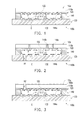
- FIG. 1 is a schematic cross-sectional view illustrating a heat dissipation plate according to an embodiment of the invention.
- FIG. 2 is a schematic cross-sectional view illustrating a heat dissipation plate according to another embodiment of the invention.
- FIG. 3 is a schematic cross-sectional view illustrating a heat dissipation plate according to another embodiment of the invention.
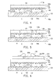
- FIG. 4 is a schematic cross-sectional view illustrating a heat dissipation plate according to another embodiment of the invention.
- FIG. 5 is a schematic cross-sectional view illustrating a heat dissipation plate according to another embodiment of the invention.
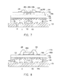
- FIG. 6 is a schematic cross-sectional view illustrating a heat dissipation plate which holds a heat generating element according to an embodiment of the invention.
- FIG. 7 is a schematic cross-sectional view illustrating a heat dissipation plate which holds a heat generating element according to another embodiment of the invention.
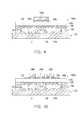
- FIG. 8 is a schematic cross-sectional view illustrating a heat dissipation plate which holds a heat generating element according to another embodiment of the invention.
- FIG. 9 is a schematic cross-sectional view illustrating a heat dissipation plate which holds a heat generating element according to another embodiment of the invention.
- FIG. 10 is a schematic cross-sectional view illustrating a heat dissipation plate which holds a heat generating element according to another embodiment of the invention.
- FIG. 1 is a schematic cross-sectional view illustrating a heat dissipation plate according to an embodiment of the invention.
- a heat dissipation plate 100a in the present embodiment includes a heat-conductive material layer 110a, a first metal layer 120, a metal substrate 130, and a metal ring frame 140.
- the heat-conductive material layer 110a has an upper surface 112a and a lower surface 114a opposite to each other; in particular, a material of the heat-conductive material layer 110a includes ceramic or silicon germanium.
- the first metal layer 120 is disposed on the lower surface 114a of the heat-conductive material layer 110a and has a first rough surface structure 122.
- the metal substrate 130 is disposed below the first metal layer 120 and has a second rough surface structure 132.
- the metal ring frame 140 is disposed between the first metal layer 120 and the metal substrate 130.
- the first rough surface structure 122, the metal ring frame 140, and the second rough surface structure 132 define a fluid chamber C, and a working fluid F flows in the fluid chamber C.
- the first metal layer 120 described in the present embodiment is in direct contact with the lower surface 114a of the heat-conductive material layer 110a.
- a material of the first metal layer 120, a material of the metal substrate 130, and a material of the metal ring frame 140 include copper, aluminum, or an alloy thereof, wherein the materials of the first metal layer 120, the metal substrate 130, and the metal ring frame 140 can be the same or different, and the invention does not pose any limitation thereto.
- the fluid chamber C for example, is a low-vacuum-level chamber
- the working fluid F for example, is air or liquid.
- the first rough surface structure 122 of the first metal layer 120 described in the present embodiment is a continuous concave-convex surface structure or a non-continuous concave-convex surface structure, and the Rymax of the first rough surface structure 122 ranges from several micrometers to several centimeters.
- the first rough surface structure 122 may be considered as a capillary structure.
- the second rough surface structure 132 of the metal substrate 130 described in the present embodiment for example, is a continuous concave-convex surface structure or a non-continuous concave-convex surface structure, and the Rymax of the second rough surface structure 132 ranges from several micrometers to several centimeters.
- the second rough surface structure 132 may also be considered as a capillary structure.
- the first rough surface structure 122 and the second rough surface structure 132 are formed by mechanical processing (e.g., computer numerical control (CNC) milling, stamping, or sandblasting), chemical processing (e.g., electrochemical plating or etching), or physical grinding, which should not be construed as limitations to the invention.
- CNC computer numerical control
- stamping stamping
- sandblasting chemical processing
- electrochemical plating or etching electrochemical plating or etching
- physical grinding which should not be construed as limitations to the invention.
- the material of the heat-conductive material layer 110a of the heat dissipation plate 100a described in the present embodiment is ceramic or silicon germanium having high thermal conductivity, and the first rough surface structure 122 of the first metal layer 120, the metal ring frame 140, and the second rough surface structure 132 of the metal substrate 130 define a low-vacuum-level fluid chamber C. Accordingly, as a heat generating element (not shown) is disposed on the heat-conductive material layer 110a, the working fluid F inside the fluid chamber C absorbs heat E generated by the heat generating element and vaporizes on a low vacuum condition. At this time, the working fluid F absorbs the heat E and rapidly expands its volume, and the gas-phase working fluid F soon fills the whole fluid chamber C.
- the gas-phase working fluid F When the gas-phase working fluid F is in contact with areas with low temperature, the gas-phase working fluid F is condensed, so as to allow the heat absorbed during vaporization to be released. After condensation, the liquid-phase working fluid F returns to the evaporating region (i.e., below the heat generating element) via a capillary action of the first rough surface structure 122 and the second rough surface structure 132. Therefore, via the repeated cycles of conduction, evaporation, convection, and condensation, the heat E generated by the heat generating element can be rapidly transferred to each portion of the heat dissipation plate 100a.
- the heat dissipation plate 100a described in the present embodiment can be considered a vapor chamber having a flat structure and the satisfactory two-phase flow characteristics. Thereby, an excellent two-dimensional lateral thermal conduction effect may be provided, the heat generated by the heat generating element may be rapidly diffused to avoid a formation of hot spots in local regions, and the lifetime of the heat generating element may be extended.
- the heat-conducting material layer 110a achieves thermal conduction effects, and the thermal expansion coefficient of the heat-conducting material layer 110a is relatively close to the thermal expansion coefficient of the heat generating element (not shown). Therefore, as the heat generating element is disposed on the heat-conductive material layer 110a, the difference of thermal expansion coefficients between the heat dissipation plate 100a and the heat generating element held by the heat dissipation plate 100a may be reduced, the corresponding stress increase between the heat generating element and the heat-conductive material layer 110a due to the significant difference between the two thermal expansion coefficients can be avoided, the heat generating element may be prevented from falling off or being damaged, and the reliability of the heat dissipation plate 100a may be enhanced.
- FIG. 2 is a schematic cross-sectional view illustrating a heat dissipation plate according to another embodiment of the invention.
- the heat dissipation plate 100b in the present embodiment is similar to the heat dissipation plate 100a in FIG. 1 , and one of main differences is that the heat-conductive material layer 110b in the present embodiment has at least one conductive through hole structure 116b ( FIG. 2 schematically illustrates three hole structures), and the conductive through hole structure 116b is connected to the upper surface 112b and the lower surface 114b and exposes a portion of the first metal layer 120.
- the conductive through hole structure 116b is electrically connected to the exposed portion of the first metal layer 120.
- the heat dissipation plate 100b further includes at least one opening H1, wherein the opening H1 penetrates through the metal substrate 130 and communicates with the fluid chamber C to improve the overall heat dissipation efficiency of the heat dissipation plate 100b by sucking gas from or injecting fluid into the fluid chamber C through the opening H1.
- a thin metal pipe (not shown) may be inserted into the opening H1 for gas suction or fluid injection, such that the fluid chamber C is in a low vacuum state; after that, the inserted thin metal pipe is closed.
- FIG. 3 is a schematic cross-sectional view illustrating a heat dissipation plate according to another embodiment of the invention.
- the heat dissipation plate 100c in the present embodiment is similar to the heat dissipation plate 100a in FIG. 1 , and one of main differences is that the heat dissipation plate 100c in the present embodiment further includes a second metal layer 160a.
- the second metal layer 160a is disposed on the upper surface 112a of the heat-conductive material layer 110a, and the second metal layer 160a entirely covers the heat-conductive material layer 110a.
- the heat dissipation plate 100c further includes at least one opening H2.
- the opening H2 sequentially penetrates through the second metal layer 160a, the heat-conductive material 110a, and the first metal layer 120 and communicates with the fluid chamber C to improve the overall heat dissipation efficiency of the heat dissipation plate 100c by sucking gas from or injecting fluid into the fluid chamber C through the opening H2.
- FIG. 4 is a schematic cross-sectional view illustrating a heat dissipation plate according to another embodiment of the invention.
- the heat dissipation plate 100d in the present embodiment is similar to the heat dissipation plate 100a in FIG. 1 , and one of main differences is that the heat dissipation plate 100d in the present embodiment further includes a second metal layer 160b.
- the second metal layer 160b is disposed on the upper surface 112a of the heat-conductive material layer 110a, and the second metal layer 160b covers the heat-conductive material layer 110a and exposes a portion of the upper surface 112a of the heat-conductive material layer 110a.
- the heat dissipation plate 100d further includes at least one opening H3, and the opening H3 penetrates through the metal ring frame 140 and communicates with the fluid chamber C to improve the overall heat dissipation efficiency of the heat dissipation plate 100d by sucking gas from or injecting fluid into the fluid chamber C through the opening H3.
- FIG. 5 is a schematic cross-sectional view illustrating a heat dissipation plate according to another embodiment of the invention.
- the heat dissipation plate 100e in the present embodiment is similar to the heat dissipation plate 100b in FIG. 2 , and one of main differences is that the heat dissipation plate 100e in the present embodiment further includes a second metal layer 160b.
- the second metal layer 160b is disposed on the upper surface 112b of the heat-conductive material layer 110b, and the second metal layer 160b covers the heat-conductive material layer 110b and exposes a portion of the upper surface 112b of the heat-conductive material layer 110b.
- the conductive through hole structure 116b, the second metal layers 160a and 160b, and the openings H1, H2, and H3 are also applicable in other embodiments not shown herein. According to the above descriptions in the previous embodiments, people having the ordinary skill in the art can use the aforementioned components to achieve the desired technical effects based on the actual requirements.
- FIG. 6 is a schematic cross-sectional view illustrating a heat dissipation plate which holds a heat generating element according to an embodiment of the invention.
- the heat dissipation plate 100a is suitable for carrying a LED chip 200a (i.e., the heat generating element), and the LED chip 200a is embedded in a dielectric layer 210 and electrically connected to circuits 230 on the dielectric layer 210 through a plurality of bonding wires 220.
- the LED chip 200a and the dielectric layer 210 are fixed onto the upper surface 112a of the heat-conductive material layer 110a by an adhesive layer 240.
- the adhesive layer 240 for example, can be a conductive adhesive layer or a non-conductive adhesive layer, and the invention does not pose any limitation thereto.
- the heat-conductive material layer 110a in present embodiment achieves the heat dissipation effects, and the thermal expansion coefficient of the heat-conductive material layer 110a is close to the thermal expansion coefficient of the LED chip 200a (not shown). Therefore, as the LED chip 200a is disposed on the heat-conductive material layer 110a by the adhesive layer 240, the difference of thermal expansion coefficients between the heat dissipation plate 100a and the LED chip 200a held by the heat dissipation plate 100a may be effectively reduced, the corresponding stress increase between the heat generating element and the heat-conductive material layer 110a due to the significant difference between the two thermal expansion coefficients can be avoided, the LED chip 200a may be prevented from falling off or being damaged, and the reliability of the heat dissipation plate 100a may be enhanced. Furthermore, if the heat dissipation plate 100a only has the function of heat dissipation, the heat generated by the LED chip 200a may be rapidly transmitted to the external surroundings through the cycles of conduction, evaporation, convection, and condensation.
- the invention does not limit the number of the LED chips 200a, although only one LED chip 200a is exemplified herein.
- the heat generating element can also be composed of a plurality of LED chips 200b connected in series or in parallel. This still belongs to a technical means adoptable in the invention and falls within the protection scope of the invention.
- FIG. 8 is a schematic cross-sectional view illustrating a heat dissipation plate which holds a heat generating element according to another embodiment of the invention.
- the heat dissipation plate 100d is suitable for carrying a LED chip 200d (i.e., the heat generating element), wherein the LED chip 200d is disposed on the second metal layer 160b, and the LED chip 200d is structurally and electrically connected to the second metal layer 160b through a plurality of bonding wires 220.
- the heat dissipation plate 100d not only has the function of heat dissipation but also has the function of electrical conduction.
- FIG. 9 is a schematic cross-sectional view illustrating a heat dissipation plate which holds a heat generating element according to another embodiment of the invention.
- the heat dissipation plate 100d is suitable for carrying a LED chip 200e (i.e., the heat generating element), wherein the LED chip 200e is disposed on the second metal layer 160b through the silver paste 250; that is, the LED chip 200e is electrically connected to the second metal layer 160b of the heat dissipation plate 100d by flip chip bonding.
- the heat dissipation plate 100d not only has the function of heat dissipation but also has the function of electrical conduction.
- the invention does not limit the number of the LED chips 200e, although only one LED chip 200e is exemplified herein.
- the heat generating element can also be composed of a plurality of LED chips 200f.
- the heat dissipation plate 100b, 100c, and 100d as mentioned above are applicable in other embodiments not shown herein. According to the above descriptions in the previous embodiments, people having the ordinary skill in the art can use the aforementioned components to achieve the desired technical effects based on the actual requirements.
- the material of the heat-conductive material layer of the heat dissipation plate described in the invention is ceramic or silicon germanium having high thermal conductivity.
- the first rough surface structure of the first metal layer, the metal ring frame, and the second rough surface structure of the metal substrate define a low-vacuum-level fluid chamber. Therefore, the heat dissipation plate described in the invention can be considered as a vapor chamber, and when the heat generating element (e.g., a LED chip) is disposed on the heat dissipation plate, the heat generated by the heat generating element can be dissipated due to the two-phase flow characteristics of the vapor chamber. Thereby, the heat generated by the heat generating element can be removed efficiently, and the efficiency and the lifetime of the heat generating element can be increased.
- the heat generating element e.g., a LED chip
Landscapes
- Engineering & Computer Science (AREA)
- Physics & Mathematics (AREA)
- Thermal Sciences (AREA)
- Mechanical Engineering (AREA)
- General Engineering & Computer Science (AREA)
- Ceramic Engineering (AREA)
- Life Sciences & Earth Sciences (AREA)
- Sustainable Development (AREA)
- Cooling Or The Like Of Semiconductors Or Solid State Devices (AREA)
- Led Device Packages (AREA)
- Resistance Heating (AREA)
Applications Claiming Priority (1)
| Application Number | Priority Date | Filing Date | Title |
|---|---|---|---|
| TW102117918A TWI513069B (zh) | 2013-05-21 | 2013-05-21 | 散熱板 |
Publications (3)
| Publication Number | Publication Date |
|---|---|
| EP2806455A2 true EP2806455A2 (fr) | 2014-11-26 |
| EP2806455A3 EP2806455A3 (fr) | 2016-08-24 |
| EP2806455B1 EP2806455B1 (fr) | 2018-07-04 |
Family
ID=48792976
Family Applications (1)
| Application Number | Title | Priority Date | Filing Date |
|---|---|---|---|
| EP13175376.6A Not-in-force EP2806455B1 (fr) | 2013-05-21 | 2013-07-05 | Plaque de dissipation de chaleur |
Country Status (5)
| Country | Link |
|---|---|
| US (2) | US20140345841A1 (fr) |
| EP (1) | EP2806455B1 (fr) |
| JP (1) | JP5840663B2 (fr) |
| CN (1) | CN104183690B (fr) |
| TW (1) | TWI513069B (fr) |
Cited By (3)
| Publication number | Priority date | Publication date | Assignee | Title |
|---|---|---|---|---|
| CN109891178A (zh) * | 2017-09-19 | 2019-06-14 | 华为技术有限公司 | 由冲压工艺形成的薄型均热板 |
| WO2019201660A1 (fr) * | 2018-04-19 | 2019-10-24 | Siemens Aktiengesellschaft | Système de refroidissement pour composants électriques, convertisseur pourvu d'un système de refroidissement et aéronef pourvu d'un convertisseur |
| TWI791342B (zh) * | 2021-11-30 | 2023-02-01 | 財團法人工業技術研究院 | 異質整合半導體封裝結構 |
Families Citing this family (12)
| Publication number | Priority date | Publication date | Assignee | Title |
|---|---|---|---|---|
| CN104538372B (zh) * | 2014-12-29 | 2018-05-22 | 华进半导体封装先导技术研发中心有限公司 | 散热型封装结构及其制作方法、散热型封装基板 |
| JP6799503B2 (ja) * | 2016-12-14 | 2020-12-16 | 新光電気工業株式会社 | ヒートパイプ及びその製造方法 |
| CN109257903B (zh) * | 2017-07-12 | 2024-07-02 | 深圳市蓝海华腾技术股份有限公司 | 流管散热装置及其制造方法 |
| TW202022301A (zh) * | 2018-12-04 | 2020-06-16 | 十銓科技股份有限公司 | 水冷式固態硬碟裝置 |
| JP7197346B2 (ja) * | 2018-12-19 | 2022-12-27 | 新光電気工業株式会社 | ループ型ヒートパイプ |
| CN111615293B (zh) * | 2019-02-26 | 2025-09-09 | 嘉联益科技(苏州)有限公司 | 线路板模块及其散热板结构 |
| TWI686108B (zh) | 2019-02-26 | 2020-02-21 | 嘉聯益科技股份有限公司 | 線路板模組及其散熱板結構 |
| CN111551059A (zh) * | 2020-06-10 | 2020-08-18 | 杭州本松新材料技术股份有限公司 | 一种塑料平板均热板及其制造方法 |
| US20210408619A1 (en) * | 2020-06-30 | 2021-12-30 | Valeo North America, Inc. | Heat exchange interface and a method of configuring the same |
| CN216385225U (zh) * | 2020-12-16 | 2022-04-26 | 安徽维鸿电子科技有限公司 | 回路热管 |
| CN115360099B (zh) * | 2022-08-22 | 2025-09-12 | 深圳市电通材料技术有限公司 | 一种散热器件及其制备方法 |
| CN116321969B (zh) * | 2023-03-16 | 2024-12-24 | 华为技术有限公司 | 一种散热结构及电子设备 |
Family Cites Families (37)
| Publication number | Priority date | Publication date | Assignee | Title |
|---|---|---|---|---|
| US4322737A (en) * | 1979-11-20 | 1982-03-30 | Intel Corporation | Integrated circuit micropackaging |
| US7051793B1 (en) * | 1998-04-20 | 2006-05-30 | Jurgen Schulz-Harder | Cooler for electrical components |
| DE10017971A1 (de) * | 2000-04-11 | 2001-10-25 | Bosch Gmbh Robert | Kühlvorrichtung zur Kühlung von Bauelementen der Leistungselektronik mit einem Mikrowärmeübertrager |
| JP4055458B2 (ja) * | 2001-05-11 | 2008-03-05 | 株式会社デンソー | 沸騰冷却装置 |
| JP2002357393A (ja) * | 2001-06-04 | 2002-12-13 | Sansha Electric Mfg Co Ltd | 液冷型半導体モジュール |
| US6834713B2 (en) * | 2002-07-18 | 2004-12-28 | Delphi Technologies, Inc. | Thermosiphon for electronics cooling with nonuniform airflow |
| DE10261402A1 (de) * | 2002-12-30 | 2004-07-15 | Schulz-Harder, Jürgen, Dr.-Ing. | Wärmesenke in Form einer Heat-Pipe sowie Verfahren zum Herstellen einer solchen Wärmesenke |
| TWI235817B (en) * | 2004-03-26 | 2005-07-11 | Delta Electronics Inc | Heat-dissipating module |
| TWI236870B (en) * | 2004-06-29 | 2005-07-21 | Ind Tech Res Inst | Heat dissipation apparatus with microstructure layer and manufacture method thereof |
| US6997244B2 (en) * | 2004-07-16 | 2006-02-14 | Hsu Hul-Chun | Wick structure of heat pipe |
| US20060175044A1 (en) * | 2005-02-10 | 2006-08-10 | Chin-Wei Lee | Heat dissipating tube sintered with copper powders |
| CN100420912C (zh) * | 2005-06-08 | 2008-09-24 | 财团法人工业技术研究院 | 热传组件的复合式毛细结构 |
| DE102006006175A1 (de) * | 2006-02-10 | 2007-08-23 | Ecpe Engineering Center For Power Electronics Gmbh | Leistungselektronikanordnung |
| US8482921B2 (en) * | 2006-10-23 | 2013-07-09 | Teledyne Scientific & Imaging, Llc. | Heat spreader with high heat flux and high thermal conductivity |
| TW200829137A (en) * | 2006-12-22 | 2008-07-01 | Foxconn Tech Co Ltd | Heat dissipation assembly for light emitting diode |
| WO2008078788A1 (fr) * | 2006-12-26 | 2008-07-03 | Kyocera Corporation | Substrat de dissipation de chaleur et dispositif électronique utilisant un tel substrat |
| US7902957B2 (en) * | 2007-04-30 | 2011-03-08 | Rockwell Automation Technologies, Inc. | Phase change cooled electrical resistor |
| US8507320B2 (en) * | 2008-03-18 | 2013-08-13 | Infineon Technologies Ag | Electronic device including a carrier and a semiconductor chip attached to the carrier and manufacturing thereof |
| US20090308576A1 (en) * | 2008-06-17 | 2009-12-17 | Wang Cheng-Tu | Heat pipe with a dual capillary structure and manufacturing method thereof |
| TWM361859U (en) * | 2009-02-05 | 2009-07-21 | Jung-Chang Wang | A micro uniform temperature substrate for mounting electronic elements |
| US9163883B2 (en) * | 2009-03-06 | 2015-10-20 | Kevlin Thermal Technologies, Inc. | Flexible thermal ground plane and manufacturing the same |
| US20100294467A1 (en) * | 2009-05-22 | 2010-11-25 | General Electric Company | High performance heat transfer device, methods of manufacture thereof and articles comprising the same |
| US20100294461A1 (en) * | 2009-05-22 | 2010-11-25 | General Electric Company | Enclosure for heat transfer devices, methods of manufacture thereof and articles comprising the same |
| US8159821B2 (en) * | 2009-07-28 | 2012-04-17 | Dsem Holdings Sdn. Bhd. | Diffusion bonding circuit submount directly to vapor chamber |
| EP3540772A1 (fr) * | 2009-09-16 | 2019-09-18 | Semiconductor Energy Laboratory Co., Ltd. | Transistor et afficheur |
| JP2011096994A (ja) * | 2009-09-29 | 2011-05-12 | Kyocera Corp | 冷却器、配線基板、および発光体 |
| WO2011058436A2 (fr) * | 2009-11-10 | 2011-05-19 | Dsem Holdings Sdn. Bhd. | Carte de circuit imprimé formant les parois soudées par diffusion d'une chambre de vapeur |
| US20110122630A1 (en) * | 2009-11-26 | 2011-05-26 | Dsem Holdings Sdn. Bhd. | Solid State Lamp Having Vapor Chamber |
| US20120111542A1 (en) * | 2010-11-09 | 2012-05-10 | Alcoa Inc. | Coiled heat pipes and methods thereof |
| TWI435484B (zh) * | 2011-04-07 | 2014-04-21 | 矽品精密工業股份有限公司 | 發光二極體封裝結構 |
| JP2012229879A (ja) * | 2011-04-27 | 2012-11-22 | Fujikura Ltd | 扁平型ヒートパイプおよびその製造方法 |
| JP2013002641A (ja) * | 2011-06-10 | 2013-01-07 | Fujikura Ltd | 扁平型ヒートパイプおよびその製造方法 |
| US9061382B2 (en) * | 2011-07-25 | 2015-06-23 | International Business Machines Corporation | Heat sink structure with a vapor-permeable membrane for two-phase cooling |
| TWI462194B (zh) * | 2011-08-25 | 2014-11-21 | 南茂科技股份有限公司 | 半導體封裝結構及其製作方法 |
| JP5567059B2 (ja) * | 2012-04-05 | 2014-08-06 | 古河電気工業株式会社 | 薄型ヒートパイプ |
| CN202617585U (zh) * | 2012-05-29 | 2012-12-19 | 讯凯国际股份有限公司 | 水冷式散热装置 |
| US9220184B2 (en) * | 2013-03-15 | 2015-12-22 | Hamilton Sundstrand Corporation | Advanced cooling for power module switches |
-
2013
- 2013-05-21 TW TW102117918A patent/TWI513069B/zh not_active IP Right Cessation
- 2013-07-03 CN CN201310275893.6A patent/CN104183690B/zh not_active Expired - Fee Related
- 2013-07-05 EP EP13175376.6A patent/EP2806455B1/fr not_active Not-in-force
- 2013-07-05 US US13/935,580 patent/US20140345841A1/en not_active Abandoned
- 2013-09-12 JP JP2013189365A patent/JP5840663B2/ja not_active Expired - Fee Related
-
2016
- 2016-06-14 US US15/181,434 patent/US20160282055A1/en not_active Abandoned
Cited By (4)
| Publication number | Priority date | Publication date | Assignee | Title |
|---|---|---|---|---|
| CN109891178A (zh) * | 2017-09-19 | 2019-06-14 | 华为技术有限公司 | 由冲压工艺形成的薄型均热板 |
| WO2019201660A1 (fr) * | 2018-04-19 | 2019-10-24 | Siemens Aktiengesellschaft | Système de refroidissement pour composants électriques, convertisseur pourvu d'un système de refroidissement et aéronef pourvu d'un convertisseur |
| TWI791342B (zh) * | 2021-11-30 | 2023-02-01 | 財團法人工業技術研究院 | 異質整合半導體封裝結構 |
| US11942396B2 (en) | 2021-11-30 | 2024-03-26 | Industrial Technology Research Institute | Heterogeneous integration semiconductor package structure |
Also Published As
| Publication number | Publication date |
|---|---|
| CN104183690A (zh) | 2014-12-03 |
| EP2806455B1 (fr) | 2018-07-04 |
| US20140345841A1 (en) | 2014-11-27 |
| EP2806455A3 (fr) | 2016-08-24 |
| JP5840663B2 (ja) | 2016-01-06 |
| JP2014228270A (ja) | 2014-12-08 |
| US20160282055A1 (en) | 2016-09-29 |
| TW201445785A (zh) | 2014-12-01 |
| CN104183690B (zh) | 2017-09-15 |
| TWI513069B (zh) | 2015-12-11 |
Similar Documents
| Publication | Publication Date | Title |
|---|---|---|
| EP2806455A2 (fr) | Plaque de dissipation de chaleur | |
| US8970029B2 (en) | Thermally enhanced heat spreader for flip chip packaging | |
| US9741638B2 (en) | Thermal structure for integrated circuit package | |
| US20150034976A1 (en) | Led chip-on-board type flexible pcb and flexible heat spreader sheet pad and heat-sink structure using the same | |
| TWI508238B (zh) | 晶片散熱系統 | |
| US20200091036A1 (en) | Semiconductor package structure | |
| JP2016096329A (ja) | 複数の光素子からの熱除去 | |
| JP5992472B2 (ja) | 放熱基板 | |
| US11139226B2 (en) | Semiconductor package structure and assembly structure | |
| US10236429B2 (en) | Mounting assembly and lighting device | |
| EP2150974A1 (fr) | Boîtier de circuit intégré à couvercle soudé pour améliorer le rendement thermique | |
| US20130313606A1 (en) | Illuminating device | |
| US7584622B2 (en) | Localized refrigerator apparatus for a thermal management device | |
| CN101587887A (zh) | 发光二极管结构 | |
| RU2011154696A (ru) | Гибридная интегральная схема свч | |
| US8258540B2 (en) | LED package | |
| US20130032828A1 (en) | Led light strip module structure | |
| US20150014839A1 (en) | Electronic Element Packaging Structure and Carrier Substrate Thereof | |
| US11217502B2 (en) | Semiconductor device packages and methods of manufacturing the same | |
| US20240170364A1 (en) | Semiconductor package structure | |
| TWI442609B (zh) | 發光二極體封裝結構 | |
| KR101012819B1 (ko) | Plc칩과 방열판이 일체화된 패키지 | |
| KR101180378B1 (ko) | 방열 효율을 개선한 엘이디 장치 및 그의 제조 방법 | |
| TW201242121A (en) | Metal substrate structure with LED |
Legal Events
| Date | Code | Title | Description |
|---|---|---|---|
| PUAI | Public reference made under article 153(3) epc to a published international application that has entered the european phase |
Free format text: ORIGINAL CODE: 0009012 |
|
| 17P | Request for examination filed |
Effective date: 20130708 |
|
| AK | Designated contracting states |
Kind code of ref document: A2 Designated state(s): AL AT BE BG CH CY CZ DE DK EE ES FI FR GB GR HR HU IE IS IT LI LT LU LV MC MK MT NL NO PL PT RO RS SE SI SK SM TR |
|
| AX | Request for extension of the european patent |
Extension state: BA ME |
|
| PUAL | Search report despatched |
Free format text: ORIGINAL CODE: 0009013 |
|
| AK | Designated contracting states |
Kind code of ref document: A3 Designated state(s): AL AT BE BG CH CY CZ DE DK EE ES FI FR GB GR HR HU IE IS IT LI LT LU LV MC MK MT NL NO PL PT RO RS SE SI SK SM TR |
|
| AX | Request for extension of the european patent |
Extension state: BA ME |
|
| RIC1 | Information provided on ipc code assigned before grant |
Ipc: H01L 23/427 20060101AFI20160715BHEP Ipc: H01L 23/373 20060101ALI20160715BHEP Ipc: F28F 21/04 20060101ALI20160715BHEP |
|
| RBV | Designated contracting states (corrected) |
Designated state(s): AL AT BE BG CH CY CZ DE DK EE ES FI FR GB GR HR HU IE IS IT LI LT LU LV MC MK MT NL NO PL PT RO RS SE SI SK SM TR |
|
| STAA | Information on the status of an ep patent application or granted ep patent |
Free format text: STATUS: EXAMINATION IS IN PROGRESS |
|
| 17Q | First examination report despatched |
Effective date: 20170804 |
|
| GRAP | Despatch of communication of intention to grant a patent |
Free format text: ORIGINAL CODE: EPIDOSNIGR1 |
|
| STAA | Information on the status of an ep patent application or granted ep patent |
Free format text: STATUS: GRANT OF PATENT IS INTENDED |
|
| INTG | Intention to grant announced |
Effective date: 20180206 |
|
| GRAS | Grant fee paid |
Free format text: ORIGINAL CODE: EPIDOSNIGR3 |
|
| GRAA | (expected) grant |
Free format text: ORIGINAL CODE: 0009210 |
|
| STAA | Information on the status of an ep patent application or granted ep patent |
Free format text: STATUS: THE PATENT HAS BEEN GRANTED |
|
| AK | Designated contracting states |
Kind code of ref document: B1 Designated state(s): AL AT BE BG CH CY CZ DE DK EE ES FI FR GB GR HR HU IE IS IT LI LT LU LV MC MK MT NL NO PL PT RO RS SE SI SK SM TR |
|
| REG | Reference to a national code |
Ref country code: GB Ref legal event code: FG4D |
|
| REG | Reference to a national code |
Ref country code: CH Ref legal event code: EP |
|
| REG | Reference to a national code |
Ref country code: AT Ref legal event code: REF Ref document number: 1015423 Country of ref document: AT Kind code of ref document: T Effective date: 20180715 |
|
| REG | Reference to a national code |
Ref country code: IE Ref legal event code: FG4D |
|
| REG | Reference to a national code |
Ref country code: DE Ref legal event code: R096 Ref document number: 602013039626 Country of ref document: DE |
|
| REG | Reference to a national code |
Ref country code: NL Ref legal event code: MP Effective date: 20180704 |
|
| REG | Reference to a national code |
Ref country code: LT Ref legal event code: MG4D |
|
| REG | Reference to a national code |
Ref country code: AT Ref legal event code: MK05 Ref document number: 1015423 Country of ref document: AT Kind code of ref document: T Effective date: 20180704 |
|
| PG25 | Lapsed in a contracting state [announced via postgrant information from national office to epo] |
Ref country code: NL Free format text: LAPSE BECAUSE OF FAILURE TO SUBMIT A TRANSLATION OF THE DESCRIPTION OR TO PAY THE FEE WITHIN THE PRESCRIBED TIME-LIMIT Effective date: 20180704 |
|
| PG25 | Lapsed in a contracting state [announced via postgrant information from national office to epo] |
Ref country code: IS Free format text: LAPSE BECAUSE OF FAILURE TO SUBMIT A TRANSLATION OF THE DESCRIPTION OR TO PAY THE FEE WITHIN THE PRESCRIBED TIME-LIMIT Effective date: 20181104 Ref country code: RS Free format text: LAPSE BECAUSE OF FAILURE TO SUBMIT A TRANSLATION OF THE DESCRIPTION OR TO PAY THE FEE WITHIN THE PRESCRIBED TIME-LIMIT Effective date: 20180704 Ref country code: LT Free format text: LAPSE BECAUSE OF FAILURE TO SUBMIT A TRANSLATION OF THE DESCRIPTION OR TO PAY THE FEE WITHIN THE PRESCRIBED TIME-LIMIT Effective date: 20180704 Ref country code: AT Free format text: LAPSE BECAUSE OF FAILURE TO SUBMIT A TRANSLATION OF THE DESCRIPTION OR TO PAY THE FEE WITHIN THE PRESCRIBED TIME-LIMIT Effective date: 20180704 Ref country code: GR Free format text: LAPSE BECAUSE OF FAILURE TO SUBMIT A TRANSLATION OF THE DESCRIPTION OR TO PAY THE FEE WITHIN THE PRESCRIBED TIME-LIMIT Effective date: 20181005 Ref country code: PL Free format text: LAPSE BECAUSE OF FAILURE TO SUBMIT A TRANSLATION OF THE DESCRIPTION OR TO PAY THE FEE WITHIN THE PRESCRIBED TIME-LIMIT Effective date: 20180704 Ref country code: NO Free format text: LAPSE BECAUSE OF FAILURE TO SUBMIT A TRANSLATION OF THE DESCRIPTION OR TO PAY THE FEE WITHIN THE PRESCRIBED TIME-LIMIT Effective date: 20181004 Ref country code: FI Free format text: LAPSE BECAUSE OF FAILURE TO SUBMIT A TRANSLATION OF THE DESCRIPTION OR TO PAY THE FEE WITHIN THE PRESCRIBED TIME-LIMIT Effective date: 20180704 Ref country code: SE Free format text: LAPSE BECAUSE OF FAILURE TO SUBMIT A TRANSLATION OF THE DESCRIPTION OR TO PAY THE FEE WITHIN THE PRESCRIBED TIME-LIMIT Effective date: 20180704 Ref country code: CZ Free format text: LAPSE BECAUSE OF FAILURE TO SUBMIT A TRANSLATION OF THE DESCRIPTION OR TO PAY THE FEE WITHIN THE PRESCRIBED TIME-LIMIT Effective date: 20180704 Ref country code: BG Free format text: LAPSE BECAUSE OF FAILURE TO SUBMIT A TRANSLATION OF THE DESCRIPTION OR TO PAY THE FEE WITHIN THE PRESCRIBED TIME-LIMIT Effective date: 20181004 |
|
| PG25 | Lapsed in a contracting state [announced via postgrant information from national office to epo] |
Ref country code: LV Free format text: LAPSE BECAUSE OF FAILURE TO SUBMIT A TRANSLATION OF THE DESCRIPTION OR TO PAY THE FEE WITHIN THE PRESCRIBED TIME-LIMIT Effective date: 20180704 Ref country code: AL Free format text: LAPSE BECAUSE OF FAILURE TO SUBMIT A TRANSLATION OF THE DESCRIPTION OR TO PAY THE FEE WITHIN THE PRESCRIBED TIME-LIMIT Effective date: 20180704 Ref country code: ES Free format text: LAPSE BECAUSE OF FAILURE TO SUBMIT A TRANSLATION OF THE DESCRIPTION OR TO PAY THE FEE WITHIN THE PRESCRIBED TIME-LIMIT Effective date: 20180704 Ref country code: HR Free format text: LAPSE BECAUSE OF FAILURE TO SUBMIT A TRANSLATION OF THE DESCRIPTION OR TO PAY THE FEE WITHIN THE PRESCRIBED TIME-LIMIT Effective date: 20180704 |
|
| REG | Reference to a national code |
Ref country code: CH Ref legal event code: PL |
|
| PG25 | Lapsed in a contracting state [announced via postgrant information from national office to epo] |
Ref country code: LU Free format text: LAPSE BECAUSE OF NON-PAYMENT OF DUE FEES Effective date: 20180705 |
|
| REG | Reference to a national code |
Ref country code: BE Ref legal event code: MM Effective date: 20180731 |
|
| REG | Reference to a national code |
Ref country code: DE Ref legal event code: R097 Ref document number: 602013039626 Country of ref document: DE |
|
| REG | Reference to a national code |
Ref country code: IE Ref legal event code: MM4A |
|
| PG25 | Lapsed in a contracting state [announced via postgrant information from national office to epo] |
Ref country code: LI Free format text: LAPSE BECAUSE OF NON-PAYMENT OF DUE FEES Effective date: 20180731 Ref country code: IT Free format text: LAPSE BECAUSE OF FAILURE TO SUBMIT A TRANSLATION OF THE DESCRIPTION OR TO PAY THE FEE WITHIN THE PRESCRIBED TIME-LIMIT Effective date: 20180704 Ref country code: EE Free format text: LAPSE BECAUSE OF FAILURE TO SUBMIT A TRANSLATION OF THE DESCRIPTION OR TO PAY THE FEE WITHIN THE PRESCRIBED TIME-LIMIT Effective date: 20180704 Ref country code: CH Free format text: LAPSE BECAUSE OF NON-PAYMENT OF DUE FEES Effective date: 20180731 Ref country code: RO Free format text: LAPSE BECAUSE OF FAILURE TO SUBMIT A TRANSLATION OF THE DESCRIPTION OR TO PAY THE FEE WITHIN THE PRESCRIBED TIME-LIMIT Effective date: 20180704 Ref country code: IE Free format text: LAPSE BECAUSE OF NON-PAYMENT OF DUE FEES Effective date: 20180705 Ref country code: MC Free format text: LAPSE BECAUSE OF FAILURE TO SUBMIT A TRANSLATION OF THE DESCRIPTION OR TO PAY THE FEE WITHIN THE PRESCRIBED TIME-LIMIT Effective date: 20180704 |
|
| PLBE | No opposition filed within time limit |
Free format text: ORIGINAL CODE: 0009261 |
|
| STAA | Information on the status of an ep patent application or granted ep patent |
Free format text: STATUS: NO OPPOSITION FILED WITHIN TIME LIMIT |
|
| PG25 | Lapsed in a contracting state [announced via postgrant information from national office to epo] |
Ref country code: SK Free format text: LAPSE BECAUSE OF FAILURE TO SUBMIT A TRANSLATION OF THE DESCRIPTION OR TO PAY THE FEE WITHIN THE PRESCRIBED TIME-LIMIT Effective date: 20180704 Ref country code: BE Free format text: LAPSE BECAUSE OF NON-PAYMENT OF DUE FEES Effective date: 20180731 Ref country code: DK Free format text: LAPSE BECAUSE OF FAILURE TO SUBMIT A TRANSLATION OF THE DESCRIPTION OR TO PAY THE FEE WITHIN THE PRESCRIBED TIME-LIMIT Effective date: 20180704 Ref country code: SM Free format text: LAPSE BECAUSE OF FAILURE TO SUBMIT A TRANSLATION OF THE DESCRIPTION OR TO PAY THE FEE WITHIN THE PRESCRIBED TIME-LIMIT Effective date: 20180704 |
|
| 26N | No opposition filed |
Effective date: 20190405 |
|
| GBPC | Gb: european patent ceased through non-payment of renewal fee |
Effective date: 20181004 |
|
| PG25 | Lapsed in a contracting state [announced via postgrant information from national office to epo] |
Ref country code: FR Free format text: LAPSE BECAUSE OF NON-PAYMENT OF DUE FEES Effective date: 20180904 Ref country code: SI Free format text: LAPSE BECAUSE OF FAILURE TO SUBMIT A TRANSLATION OF THE DESCRIPTION OR TO PAY THE FEE WITHIN THE PRESCRIBED TIME-LIMIT Effective date: 20180704 |
|
| PG25 | Lapsed in a contracting state [announced via postgrant information from national office to epo] |
Ref country code: GB Free format text: LAPSE BECAUSE OF NON-PAYMENT OF DUE FEES Effective date: 20181004 |
|
| PG25 | Lapsed in a contracting state [announced via postgrant information from national office to epo] |
Ref country code: MT Free format text: LAPSE BECAUSE OF NON-PAYMENT OF DUE FEES Effective date: 20180705 |
|
| PG25 | Lapsed in a contracting state [announced via postgrant information from national office to epo] |
Ref country code: TR Free format text: LAPSE BECAUSE OF FAILURE TO SUBMIT A TRANSLATION OF THE DESCRIPTION OR TO PAY THE FEE WITHIN THE PRESCRIBED TIME-LIMIT Effective date: 20180704 |
|
| PG25 | Lapsed in a contracting state [announced via postgrant information from national office to epo] |
Ref country code: PT Free format text: LAPSE BECAUSE OF FAILURE TO SUBMIT A TRANSLATION OF THE DESCRIPTION OR TO PAY THE FEE WITHIN THE PRESCRIBED TIME-LIMIT Effective date: 20180704 Ref country code: HU Free format text: LAPSE BECAUSE OF FAILURE TO SUBMIT A TRANSLATION OF THE DESCRIPTION OR TO PAY THE FEE WITHIN THE PRESCRIBED TIME-LIMIT; INVALID AB INITIO Effective date: 20130705 |
|
| PG25 | Lapsed in a contracting state [announced via postgrant information from national office to epo] |
Ref country code: MK Free format text: LAPSE BECAUSE OF NON-PAYMENT OF DUE FEES Effective date: 20180704 Ref country code: CY Free format text: LAPSE BECAUSE OF FAILURE TO SUBMIT A TRANSLATION OF THE DESCRIPTION OR TO PAY THE FEE WITHIN THE PRESCRIBED TIME-LIMIT Effective date: 20180704 |
|
| PGFP | Annual fee paid to national office [announced via postgrant information from national office to epo] |
Ref country code: DE Payment date: 20210721 Year of fee payment: 9 |
|
| REG | Reference to a national code |
Ref country code: DE Ref legal event code: R119 Ref document number: 602013039626 Country of ref document: DE |
|
| PG25 | Lapsed in a contracting state [announced via postgrant information from national office to epo] |
Ref country code: DE Free format text: LAPSE BECAUSE OF NON-PAYMENT OF DUE FEES Effective date: 20230201 |