EP2806515B1 - Ensemble de chemin de câbles conducteurs, chemin de cable et et élément de retenue propres à faire partie de cet ensemble - Google Patents
Ensemble de chemin de câbles conducteurs, chemin de cable et et élément de retenue propres à faire partie de cet ensemble Download PDFInfo
- Publication number
- EP2806515B1 EP2806515B1 EP14168858.0A EP14168858A EP2806515B1 EP 2806515 B1 EP2806515 B1 EP 2806515B1 EP 14168858 A EP14168858 A EP 14168858A EP 2806515 B1 EP2806515 B1 EP 2806515B1
- Authority
- EP
- European Patent Office
- Prior art keywords
- raceway
- retainer
- vertical
- oblique section
- tab
- Prior art date
- Legal status (The legal status is an assumption and is not a legal conclusion. Google has not performed a legal analysis and makes no representation as to the accuracy of the status listed.)
- Active
Links
Images

Classifications
-
- H—ELECTRICITY
- H02—GENERATION; CONVERSION OR DISTRIBUTION OF ELECTRIC POWER
- H02G—INSTALLATION OF ELECTRIC CABLES OR LINES, OR OF COMBINED OPTICAL AND ELECTRIC CABLES OR LINES
- H02G3/00—Installations of electric cables or lines or protective tubing therefor in or on buildings, equivalent structures or vehicles
- H02G3/02—Details
- H02G3/04—Protective tubing or conduits, e.g. cable ladders or cable troughs
- H02G3/0406—Details thereof
- H02G3/0418—Covers or lids; Their fastenings
Definitions
- the invention relates to a raceway assembly for conductor cables, such as for example electrical cables or fiber optic cables, of the type comprising a raceway with a rectangular-shaped cross-section formed by a horizontal base and two vertical side walls demarcating between one another an open upper face of said raceway, each of said side walls being provided at the upper end thereof with a support configuration for fixing retainers; and at least one retainer formed by a rigid oblong part which detachably snaps at its ends onto said supports of the side walls, such that said retainer thus fixed is arranged in a bridge position, forming a rigid bridge between the upper ends of said side walls of the raceway.
- the invention also relates to a raceway and to a retainer suitable for being part of said assembly.
- raceway assemblies in the past, described in documents ES2014604A6 and ES1067776U . Although these devices satisfactorily comply with their function, they can be improved. It has particularly been observed (on rare occasions) that installers can accidentally hit one of the retainers fixed in the raceway hard enough to release it, so the installers have to then get it back. It has also been observed that when the raceway is subjected to considerable bending due to the load subjected thereto (the weight of the conductor cables themselves, the weight of the snow built up on the raceway cover, etc.), there is a risk that said bending will cause one of the retainers and/or the raceway cover to be released. The maximum distance between raceway supports is limited to avoid this risk.
- the purpose of the invention is to provide a raceway assembly of the type indicated above based on the earlier developments described in the mentioned documents ES2014604A6 and ES1067776U , and in which the fixing of the retainer in the raceway is more robust.
- Another example according to the preamble of claim 1 is known from WO 99/07048 A .
- Another objective of the invention consists of making the retainers provide greater stiffness to the raceway in a robust manner.
- Another additional objective is to make the operations that installers must perform easier, particularly while the retainer is not arranged in the final bridge position.
- the raceway is characterized in that the support configuration provided at the upper end of the side walls of the raceway comprises an oblique section of the side wall extending towards the central plane of the raceway, a vertical upper leg originating from said oblique section, and there being formed at the end of said oblique section a right angle profile with a vertical wing extending towards the base of the raceway and a horizontal wing extending back towards said vertical upper leg without actually reaching it, such that between said vertical upper leg and the end of said horizontal wing of the right angle profile there is defined an opening towards a cavity demarcated by said oblique section, said vertical upper leg and said horizontal wing.
- the retainer in turn, is characterized in that it is provided at each of its ends with at least one elbow-shaped upper tab, having a first horizontal section prolonged by a vertical end section, and at least one lower tab.
- the upper tab and lower tab of the retainer are sized so that when said retainer is arranged in the bridge position, the first horizontal section of said upper tab is supported on the upper portion of the horizontal wing of the right angle profile, and the vertical end section of said vertical tab is introduced in the cavity through the opening and supported against the vertical upper leg, whereas said lower tab is supported on the lower portion of the oblique section.
- This solution according to the invention differs from devices of the prior art, particularly, in that the support configuration provided at the upper end of the side walls of the raceway has an opening towards a cavity in which the vertical end section of the upper tab provided at the end of the retainer is introduced. This provides very firm fixing of the end of the retainer in the support configuration.
- the upper tab and the lower tab are sized so that when said retainer is arranged in an intermediate inclined position, in which said retainer extends in an inclined direction with respect to the horizontal base of the raceway and is coupled at only one of its ends to one of said support configurations of a side wall of the raceway, the other end of said retainer being in a raised position, said lower tab of the retainer is supported on the outer portion of said vertical wing of the right angle profile, whereas the vertical end section of said upper tab of the retainer is obliquely introduced in the cavity through the opening and is supported on one or several of the walls demarcating said cavity, exerting a force keeping said retainer in said intermediate inclined position.
- the installers can place the retainer in this intermediate inclined position, which the retainer can hold by itself, and gradually lay the conductor cables inside the raceway without the retainer arranged in that position getting in the way of performing this task.
- the lower tab of the retainer preferably comprises at its end a tooth forming an inclined surface such that when said retainer is arranged in the bridge position, said lower tab is supported on the lower portion of the oblique section through said inclined surface of the tooth, which is parallel to the face of said oblique section on which it is supported, and when said retainer is arranged in the intermediate inclined position, said lower tab is supported on the outer portion of said vertical wing of the right angle profile through said inclined surface of the tooth, which is parallel to the face of the vertical wing on which it is supported.
- This configuration offers, on one hand, a very robust fixing of the retainer in the bridge position, and on the other hand, good retainer stability in the intermediate inclined position.
- the retainer is provided on at least one of its longitudinal sides with a hook configured for detachably snap fastening said retainer to one of said support configurations of a side wall of the raceway, such that said retainer thus fastened by means of said hook is arranged in a stand-by position, in which said retainer extends longitudinally inside said raceway next to said side wall, said hook being provided with a curved end that is introduced in the opening defined between the vertical upper leg and the end of the horizontal wing of the right angle profile.
- This solution allows comfortably placing the retainer inside the raceway such that it is properly fastened and does not get in the way, which facilitates assembly packaging and transport to the points where it will be installed, and it also facilitates the operations of the installers who have to work with the assembly. It will be seen that this latter solution, which consists of incorporating a hook on a longitudinal side of the retainer, is itself an invention that is linked to the configuration of the raceway defined in the main claim, but not necessarily to the configuration of the retainer, in relation to the upper tab and lower tab, defined in said claim.
- the hook preferably has a shape complementary to the shape of the right angle profile formed at the end of said oblique section.
- the raceway preferably comprises on at least one of its side walls a vertical lower leg extending from the oblique section towards the base of the raceway, said vertical lower leg being positioned such that when the retainer is arranged in the stand-by position, a portion of said retainer is supported against said vertical lower leg. A particularly robust fixing of the retainer in the stand-by position is thus obtained.
- the vertical wing of the right angle profile extends towards the base of the raceway, forming a lower projection with respect to the oblique section
- the retainer comprises on the side provided with the hook at least one claw arranged such that when said retainer is arranged in the stand-by position, said claw fits in the corner formed between said lower projection and said oblique section.
- the retainer is formed by a plurality of detachable portions distributed in the longitudinal direction of said retainer, said detachable portions being provided at their ends with catch-like portions on the lower face of the retainer.
- Configuring the retainer in detachable portions, as described in the mentioned documents ES2014604A6 and ES1067776U , for the purpose of being able to use the retainer as a bridge between the side wall of the raceway and an intermediate partition placed in the raceway is known.
- the improvement introduced by the present invention consists of the detachable portions being attached to one another by side walls of the retainer in which there are through slots extending from the upper face of the retainer towards the lower edge of the side walls of the retainer, but without actually reaching said lower edge.
- the side walls of the retainer are split into sections, corresponding to the detachable portions, which are separated from one another by the through slots but attached by a bridge formed between the end of said slot and the lower edge.
- the catch-like portions are preferably arranged such that one end of one of said detachable portions has a pair of said catch-like portions which are separated from one another forming a fork, whereas the corresponding end of another one of said detachable portions, adjacent to the former, has a single one of said catch-like portions fitted in said fork formed by said pair of catch-like portions.
- This configuration is known and described in the mentioned documents ES2014604A6 and ES1067776U .
- the improvement according to the present invention consists of providing transverse breakable bridges attaching said single catch-like portion to staid pair of catch-like portions, and furthermore, preferably, longitudinal breakable bridges attaching said single catch-like portion to the end of the adjacent detachable portion. The stiffness of the retainer is even further increased as a result of these transverse and longitudinal bridges.
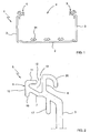
- the raceway 1 depicted in Figures 1 and 2 is a profile made from extruded thermoplastic.
- This raceway 1 has a cross-section shape which is common in raceways used for conductor cables: a horizontal base 2 and two vertical side walls 3 demarcating between one another an open upper face 4.
- the raceway 1 is characterized by the particular shape of the support configuration 5 at the upper end of each of the side walls 3 of the raceway 1, which serves for fixing a retainer 6 custom-designed for this raceway 1.
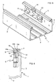
- the retainer 6 can be fixed in a bridge position ( Figure 4 ), in an intermediate inclined position ( Figure 3 ), or in a stand-by position ( Figures 5-6 ).
- This particular shape of the support configuration 5 (see Figure 2 ) consists of comprising an oblique section 7 of the side wall 3 of the raceway 1 extending towards the central plane of said raceway 1, a vertical upper leg 8 originating from said oblique section 7, and there being formed at the end of said oblique section 7 a right angle profile 9 with a vertical wing 10 extending towards the base 2 of the raceway and a horizontal wing 11 extending back towards said vertical upper leg 8 without actually reaching it, such that between said vertical upper leg 8 and the end of said horizontal wing 11 of the right angle profile 9 there is defined an opening 12 towards a cavity 13 demarcated by said oblique section 7, said vertical upper leg 8 and said horizontal wing 11. Furthermore, the vertical wing 10 of the right angle profile 9 extends towards the base 2 of the raceway forming a lower projection 18 with respect to said oblique section 7.
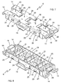
- the retainer 6 is formed by a rigid oblong part made of molded thermoplastic, and its main purpose consists, in a known manner, of detachably snapping at its ends onto support configurations 5 provided in the side walls 3 of the raceway 1.
- the retainer 6 thus fixed is arranged in a bridge position such as that shown in Figure 4 , forming a rigid bridge between the upper ends of the side walls 3 of the raceway 1.
- the retainer 6 has two main particularities which are independent from one another, but each of which is related to the particular shape of the support configuration 5 in the raceway.
- a first particularity which allows arranging the retainer 6 in the bridge position ( Figure 4 ) obtaining a particularly robust fixing, consists of said retainer 6 being provided at each of its ends with at least one elbow-shaped upper tab 14, having a first horizontal section 14a prolonged by a vertical end section 14b, and at least one lower tab 15.
- the retainer 6 comprises at each of its ends two upper tabs 14 separated from one another and a single lower tab 15 located in the center with respect to said two upper tabs 14.
- the upper tab 14 and lower tab 15 are sized such that when the retainer 6 is arranged in the bridge position, the first horizontal section 14a of the upper tab 14 is supported on the upper portion of the horizontal wing 11 of the right angle profile 9, the vertical end section 14b of the vertical tab 14 is introduced in the cavity 13 through the opening 12 and is supported against the vertical upper leg 8, and the lower tab 15 is supported on the lower portion of the oblique section 7.
- the sizing of the upper tab 14 and lower tab 15 is such that when the retainer is arranged in the intermediate inclined position shown in Figure 3 , in which said retainer 6 extends in an inclined direction with respect to the horizontal base 2 of the raceway and is coupled at only one of its ends to one of the support configurations 5 of a side wall 3 of the raceway 1, the other end of the retainer 6 being in a raised position, said lower tab 15 is supported on the outer portion of the vertical wing 10 of the right angle profile 9, whereas the vertical end section 14b of said upper tab 14 is obliquely introduced in the cavity 13 through the opening 12 and is supported on one or several of the walls demarcating said cavity 13, thus exerting a force keeping the retainer 6 in the intermediate inclined position.
- the lower tab 15 of the retainer 6 comprises at its end a tooth 28 forming an inclined surface 29 such that when the retainer 6 is arranged in the bridge position, as shown in Figure 4 , said lower tab 15 is supported on the lower portion of the oblique section 7 through the inclined surface 29 of the tooth 28, which is parallel to the face of the oblique section 7 on which it is supported; and when the retainer 6 is arranged in the intermediate inclined position shown in Figure 3 , said lower tab 15 is supported on the outer portion of the vertical wing 10 of the right angle profile 9 through said inclined surface 29 of the tooth 28, which is parallel to the face of said vertical wing 10 on which it is supported.
- a second particularity which allows arranging the retainer 6 in the stand-by position shown in Figures 5-6 , consists of the retainer 6 being provided on at least one of its longitudinal sides with a hook 16 configured for detachably snap fastening said retainer 6 to one of the support configurations 5 of one of the side walls 3 of the raceway 1.
- the retainer 6 thus fastened by means of the hook 16 is arranged in the mentioned stand-by position ( Figures 5-6 ), in which said retainer 6 extends longitudinally inside the raceway 1 next to the side wall 3 thereof.
- the retainer 6 comprises on the side provided with the hook 16 at least one claw 19 arranged such that when said retainer 6 is arranged in the stand-by position ( Figures 5-6 ), said claw 19 fits in the corner formed between the lower projection 18 and the oblique section 7.
- the hook 16 has a shape complementary to the shape of the right angle profile 9 formed at the end of said oblique section 7: said hook 16 has a first straight section 16a extending in the transverse direction of the retainer 6, a second straight section 16b orthogonal to the first, and a curved end 16c which is introduced in the opening 12 defined between the vertical upper leg 8 and the end of the horizontal wing 11 of the right angle profile 9.
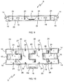
- the retainer 6 is formed in a known manner by a plurality of detachable portions 20 which are distributed in the longitudinal direction of said retainer 6 and are provided at their ends with catch-like portions 21, 22 on the lower face of said retainer 6.
- these catch-like portions 21, 22 are arranged such that one end of one of the detachable portions 20 has a pair of catch-like portions 21 separated from one another forming a fork, whereas the corresponding end of another one of the detachable portions 20, adjacent to the former, has a single catch-like portion 22 fitted in said fork formed by the pair of catch-like portions 21.
- these catch-like portions 21, 22 are intended for being coupled on the upper edge of an intermediate partition (not depicted in the drawings of the present document).
- the originality of the invention consists of improvements which seek to make the retainer 6 more rigid.
- the detachable portions 20 are attached to one another by side walls 23 of the retainer 6 in which there are through slots 24 extending from the upper face of said retainer 6 towards the lower edge 25 of said side walls 23 without actually reaching said lower edge 25.
- Transverse breakable bridges 26 attaching the single catch-like portion 22 to the pair of corresponding catch-like portions 21 are also provided.
- Longitudinal breakable bridges 27 attaching the single catch-like portion 22 to the end of the adjacent detachable portion 20 are also provided.
Landscapes
- Engineering & Computer Science (AREA)
- Architecture (AREA)
- Civil Engineering (AREA)
- Structural Engineering (AREA)
- Installation Of Indoor Wiring (AREA)
- Supports For Pipes And Cables (AREA)
Claims (10)
- Ensemble de chemin de câbles pour câbles conducteurs, comprenant un chemin de câbles (1) avec une section transversale de forme rectangulaire formée par une base horizontale (2) et deux parois latérales verticales (3) délimitant entre elles, une face supérieure ouverte (4) dudit chemin de câbles (1), chacune desdites parois latérales (3) étant prévue, au niveau de son extrémité supérieure, avec une configuration de support (5) pour fixer des dispositifs de retenue (6) ; et au moins un dispositif de retenue (6) formé par une partie oblongue rigide qui s'encliquette de manière détachable, au niveau de ses extrémités, sur lesdites configurations de support (5) des parois latérales (3), de sorte que ledit dispositif de retenue (6) ainsi fixé est agencé dans une position de pont, formant un pont rigide entre les extrémités supérieures desdites parois latérales (3) du chemin de câbles (1) ; caractérisé en ce que ladite configuration de support (5) comprend une section oblique (7) de ladite paroi latérale (3) s'étendant vers le plan central dudit chemin de câbles (1), une patte supérieure verticale (8) prenant son origine à partir de ladite section oblique (7) et formant à cet endroit, au niveau de l'extrémité de ladite section oblique (7), un profil d'angle droit (9) avec une aile verticale (10) s'étendant vers la base (2) du chemin de câbles (1) et une aile horizontale (11) revenant vers ladite patte supérieure verticale (8) sans vraiment l'atteindre, de sorte qu'entre ladite patte supérieure verticale (8) et l'extrémité de ladite aile horizontale (11) du profil d' angle droit (9), on définit une ouverture (12) vers une cavité (13) délimitée par ladite section oblique (7), ladite patte supérieure verticale (8) et ladite aile horizontale (11), et en ce que ledit au moins un dispositif de retenue (6) est prévu, au niveau de chacune de ses extrémités, avec au moins une languette supérieure en forme de coude (14) ayant une première section horizontale (14a) prolongée par une section d'extrémité verticale (14b) et au moins une languette inférieure (15), ladite languette supérieure (14) et la languette inférieure (15) du dispositif de retenue (6) étant dimensionnées de sorte que lorsque ledit dispositif de retenue (6) est agencé dans ladite position de pont, ladite première section horizontale (14a) de la languette supérieure (14) est supportée sur la partie supérieure de ladite aile horizontale (11) du profil d'angle droit (9) et ladite section d'extrémité verticale (14b) de la languette verticale (14) est introduite dans ladite cavité (13) par ladite ouverture (12) et supportée contre ladite patte supérieure verticale (8), alors que ladite languette inférieure (15) est supportée sur la partie inférieure de ladite section oblique (7).
- Ensemble de chemin de câbles pour câbles conducteurs selon la revendication 1, caractérisé en ce que dans ledit dispositif de retenue (6), ladite languette supérieure (14) et ladite languette inférieure (15) sont dimensionnées de sorte que lorsque ledit dispositif de retenue est agencé dans une position inclinée intermédiaire dans laquelle ledit dispositif de retenue (6) s'étend dans une direction inclinée par rapport à la base horizontale (2) du chemin de câbles (1) et est couplé uniquement au niveau de l'une de ses extrémités à l'une desdites configurations de support (5) d'une paroi latérale (3) du chemin de câbles (1), l'autre extrémité dudit dispositif de retenue (6) étant dans la position levée, ladite languette inférieure (15) du dispositif de retenue (6) est supportée sur la partie externe de ladite aile verticale (10) du profil d'angle droit (9), alors que ladite section d'extrémité verticale (14b) de la languette supérieure (14) du dispositif de retenue (6) est introduite obliquement dans ladite cavité (3) à travers ladite ouverture (12) et est supportée sur une ou plusieurs des parois délimitant ladite cavité (13), exerçant une force maintenant ledit dispositif de retenue (6) dans ladite position inclinée intermédiaire.
- Ensemble de chemin de câbles pour câbles conducteurs selon la revendication 2, caractérisé en ce que, dans ledit dispositif de retenue (6), ladite languette inférieure (15) comprend, au niveau de son extrémité, une dent (28) formant une surface inclinée (29) de sorte que lorsque ledit dispositif de retenue (6) est agencé dans ladite position de pont, ladite languette inférieure (15) est supportée sur la partie inférieure de ladite section oblique (7) à travers ladite surface inclinée (29) de la dent (28), qui est parallèle à la face de ladite section oblique (7) sur laquelle elle est supportée, et lorsque ledit dispositif de retenue (6) est agencé dans ladite position inclinée intermédiaire, ladite languette inférieure (15) est supportée sur la partie externe de ladite aile verticale (10) du profil d'angle droit (9) à travers ladite surface inclinée (29) de la dent (28) qui est parallèle à la face de ladite aile verticale (10) sur laquelle elle est supportée.
- Ensemble de chemin de câbles pour câbles conducteurs selon l'une quelconque des revendications 1 à 3, caractérisé en ce que ledit dispositif de retenue (6) est prévu au niveau d'au moins l'un de ses côtés longitudinaux avec un crochet (16) configuré pour fixer par encliquetage de manière détachable ledit dispositif de retenue (6) à l'une desdites configurations de support (5) d'une paroi latérale (3) du chemin de câbles (1), de sorte que ledit dispositif de retenue (6) ainsi fixé au moyen dudit crochet (16), est agencé dans une position d'attente, dans laquelle ledit dispositif de retenue (6) s'étend longitudinalement à l'intérieur dudit chemin de câbles (1) à côté de ladite paroi latérale (3), ledit crochet (16) étant prévu avec une extrémité incurvée (16c) qui est introduite dans ladite ouverture (12) définie entre ladite patte supérieure verticale (8) et l'extrémité de ladite aile horizontale (11) du profil d'angle droit (9).
- Ensemble de chemin de câbles selon la revendication 4, caractérisé en ce que ledit crochet (16) a une forme complémentaire de la forme dudit profil d'angle droit (9) formé à l'extrémité de ladite section oblique (7).
- Ensemble de chemin de câbles selon la revendication 4 ou 5, caractérisé en ce que, sur au moins l'une desdites parois latérales (3), ledit chemin de câbles (1) comprend une patte inférieure verticale (17) s'étendant à partir de ladite section oblique (7) vers ladite base (2) du chemin de câbles (1), ladite patte inférieure verticale (17) tant positionnée de sorte que lorsque ledit dispositif de retenue (6) est agencé dans ladite position d'attente, une partie dudit dispositif de retenue (6) est supportée contre ladite patte inférieure verticale (17).
- Ensemble de chemin de câbles selon l'une quelconque des revendications 4 à 6, caractérisé en ce que, dans ledit chemin de câbles (1), ladite aile verticale (10) du profil d'angle droit (9) s'étend vers ladite base (2) dudit chemin de câbles (1) formant une saillie inférieure (18) par rapport à ladite section oblique (7) et en ce que le dispositif de retenue (6) comprend, sur le côté prévu avec ledit crochet (16), au moins une griffe (19) agencée de sorte que lorsque ledit dispositif de retenue (6) est agencé dans ladite position d'attente, ladite griffe (19) est montée dans le coin formé entre ladite saillie inférieure (18) et ladite section oblique (7).
- Chemin de câbles (1) de l'ensemble de chemin de câbles pour câbles conducteurs selon la revendication 1, ledit chemin de câbles (1) ayant une section transversale de forme rectangulaire et étant formé par une base horizontale (2) et deux parois latérales verticales (3) délimitant entre elles, une face supérieure ouverte (4) dudit chemin de câbles (1), chacune desdites parois latérales (3) étant prévue au niveau de son extrémité supérieure avec une configuration de support (5) pour fixer des dispositifs de retenue (6), ledit chemin de câbles (1) étant caractérisé en ce que ladite configuration de support (5) comprend une section oblique (7) de ladite paroi latérale (3) s'étendant vers le plan central dudit chemin de câbles (1), une patte supérieure verticale (8) tirant son origine de ladite section oblique (7), et à cet endroit on forme, au niveau de l'extrémité de ladite section oblique (7), un profil d'angle droit (9) avec une aile verticale (10) s'étendant vers la base (2) du chemin de câbles (1) et une aile horizontale (11) revenant vers ladite patte supérieure verticale (8) sans vraiment l'atteindre, de sorte qu'entre ladite patte supérieure verticale (8) et l'extrémité de ladite aile horizontale (11) du profil d'angle droit (9), on définit une ouverture (12) vers une cavité (13) délimitée par ladite section oblique (7), ladite patte supérieure verticale (8) et ladite aile horizontale (11).
- Chemin de câbles (1) selon la revendication 8, caractérisé en ce qu'il comprend, dans au moins l'une desdites parois latérales (3), une patte inférieure verticale (17) s'étendant à partir de ladite section oblique (7) vers ladite base (2) du chemin de câbles (1).
- Chemin de câbles (1) selon l'une quelconque des revendications 8 ou 9, caractérisé en ce que ladite aile verticale (10) du profil d'angle droit (9) s'étend vers ladite base (2) du chemin de câbles (1) formant une saillie inférieure (18) par rapport à ladite section oblique (7).
Applications Claiming Priority (1)
| Application Number | Priority Date | Filing Date | Title |
|---|---|---|---|
| ES201330620U ES1081179Y (es) | 2013-05-21 | 2013-05-21 | "Conjunto de canal para cables conductores" |
Publications (3)
| Publication Number | Publication Date |
|---|---|
| EP2806515A2 EP2806515A2 (fr) | 2014-11-26 |
| EP2806515A3 EP2806515A3 (fr) | 2015-04-29 |
| EP2806515B1 true EP2806515B1 (fr) | 2016-08-03 |
Family
ID=48485684
Family Applications (1)
| Application Number | Title | Priority Date | Filing Date |
|---|---|---|---|
| EP14168858.0A Active EP2806515B1 (fr) | 2013-05-21 | 2014-05-19 | Ensemble de chemin de câbles conducteurs, chemin de cable et et élément de retenue propres à faire partie de cet ensemble |
Country Status (4)
| Country | Link |
|---|---|
| EP (1) | EP2806515B1 (fr) |
| ES (2) | ES1081179Y (fr) |
| PL (1) | PL2806515T3 (fr) |
| PT (1) | PT2806515T (fr) |
Families Citing this family (6)
| Publication number | Priority date | Publication date | Assignee | Title |
|---|---|---|---|---|
| CN107785832B (zh) * | 2017-12-06 | 2018-11-23 | 唐山市致胜商务信息咨询有限公司 | 一种加盖电缆桥架 |
| CN107834463B (zh) * | 2017-12-06 | 2018-11-13 | 扬州市新海食品机械有限公司 | 一种加强型加盖可调节电缆桥架 |
| CN107959267B (zh) * | 2017-12-06 | 2018-11-27 | 石美秀 | 一种加强型可调节电缆桥架 |
| CN108054697B (zh) * | 2017-12-06 | 2018-11-27 | 遵化市迅颖科技有限公司 | 一种可调节分区电缆桥架 |
| CN107769120B (zh) * | 2017-12-06 | 2018-11-20 | 江苏来德福汽车部件有限公司 | 一种加强型加盖电缆桥架 |
| JP6752259B2 (ja) * | 2018-09-19 | 2020-09-09 | 本田技研工業株式会社 | 車両 |
Family Cites Families (8)
| Publication number | Priority date | Publication date | Assignee | Title |
|---|---|---|---|---|
| ES2014604A6 (es) * | 1989-04-14 | 1990-07-16 | Aparellaje Electrico Sa | Disposicion de acoplamiento de grapas rigidizadoras de canales para conductores electricos y similares y grapa correspondiente. |
| US5942729A (en) * | 1997-08-04 | 1999-08-24 | The Siemon Company | Double hinged raceway |
| CA2348220A1 (fr) * | 2000-05-26 | 2001-11-26 | Hubbell Incorporated | Canalisation articulee a mecanisme de verrouillage |
| US6437244B1 (en) * | 2000-06-05 | 2002-08-20 | Panduit Corp. | Wiring duct system hinge arrangement |
| US6903265B1 (en) * | 2004-05-27 | 2005-06-07 | Panduit Corp. | Hinged and latched raceway |
| ITMI20050647A1 (it) * | 2005-04-14 | 2006-10-15 | Canalplast S P A | Struttura di canalina dotata di un coperchio antiscivolamento atta a contenere cavi tubazioni e simili |
| ES1067776Y (es) | 2008-04-28 | 2008-09-16 | Unex Aparellaje Electrico Sl | Retenedor de conductores electricos portados por canales |
| EP2112732A1 (fr) * | 2008-04-25 | 2009-10-28 | Unex Aparellaje Electrico S.L. | Chemin pour conducteurs électriques et dispositif de retenue pouvant être appliqué audit chemin |
-
2013
- 2013-05-21 ES ES201330620U patent/ES1081179Y/es not_active Expired - Fee Related
-
2014
- 2014-05-19 PT PT141688580T patent/PT2806515T/pt unknown
- 2014-05-19 ES ES14168858.0T patent/ES2600140T3/es active Active
- 2014-05-19 PL PL14168858T patent/PL2806515T3/pl unknown
- 2014-05-19 EP EP14168858.0A patent/EP2806515B1/fr active Active
Also Published As
| Publication number | Publication date |
|---|---|
| ES1081179Y (es) | 2013-08-30 |
| EP2806515A3 (fr) | 2015-04-29 |
| PL2806515T3 (pl) | 2017-01-31 |
| EP2806515A2 (fr) | 2014-11-26 |
| PT2806515T (pt) | 2016-11-14 |
| ES2600140T3 (es) | 2017-02-07 |
| ES1081179U (es) | 2013-06-05 |
Similar Documents
| Publication | Publication Date | Title |
|---|---|---|
| EP2806515B1 (fr) | Ensemble de chemin de câbles conducteurs, chemin de cable et et élément de retenue propres à faire partie de cet ensemble | |
| EP3066398B1 (fr) | Structure de support pour panneaux solaires et procédé de production d'une telle structure de support | |
| JP5458410B2 (ja) | 縦葺き外装構造 | |
| AU2019202881B2 (en) | Decking or flooring system, and components therefor | |
| US20150076291A1 (en) | Accessory Section for a Cable Tray System | |
| CN205663119U (zh) | 在用于并排安装的屋顶窗户的防水组件中使用的连接器元件 | |
| US20090025957A1 (en) | Extruded wire duct end cap | |
| JP2017531137A (ja) | 誘導装置 | |
| JP2015514169A (ja) | フロアを製造するための改善されたモジュラーアッセンブリー | |
| US11261601B2 (en) | Cross runner connector and cross runner connector arrangement for a suspended ceiling system | |
| US11368004B2 (en) | Flexible channel molding assemblies | |
| KR101275503B1 (ko) | 데크 연결구 | |
| EP3469166B1 (fr) | Revêtement mural | |
| EP2374954B1 (fr) | Section pour structures et structure relative | |
| ATE358755T1 (de) | Bandraster-system | |
| CN204750818U (zh) | 用于层叠部分的可拆卸的拼接物 | |
| US9145986B2 (en) | Wiring support for aircraft | |
| JP2015148327A (ja) | 化粧カバー、及び保護カバーの配設構造 | |
| ES2929809T3 (es) | Conjunto de bandeja portacables | |
| EP2784247B1 (fr) | Clôture ou revêtement pour bâtiments | |
| JP5666516B2 (ja) | 間仕切り壁の形成・取り外し方法 | |
| KR100913374B1 (ko) | 슬리브 | |
| KR20120082701A (ko) | 경량철골 천장시스템 및 그 시공방법 | |
| EP3291392B1 (fr) | Chemin de câbles | |
| AU2018204298B2 (en) | Housing for an electrical fitting in a sliding door unit |
Legal Events
| Date | Code | Title | Description |
|---|---|---|---|
| PUAI | Public reference made under article 153(3) epc to a published international application that has entered the european phase |
Free format text: ORIGINAL CODE: 0009012 |
|
| 17P | Request for examination filed |
Effective date: 20140519 |
|
| AK | Designated contracting states |
Kind code of ref document: A2 Designated state(s): AL AT BE BG CH CY CZ DE DK EE ES FI FR GB GR HR HU IE IS IT LI LT LU LV MC MK MT NL NO PL PT RO RS SE SI SK SM TR |
|
| AX | Request for extension of the european patent |
Extension state: BA ME |
|
| PUAL | Search report despatched |
Free format text: ORIGINAL CODE: 0009013 |
|
| AK | Designated contracting states |
Kind code of ref document: A3 Designated state(s): AL AT BE BG CH CY CZ DE DK EE ES FI FR GB GR HR HU IE IS IT LI LT LU LV MC MK MT NL NO PL PT RO RS SE SI SK SM TR |
|
| AX | Request for extension of the european patent |
Extension state: BA ME |
|
| RIC1 | Information provided on ipc code assigned before grant |
Ipc: H02G 3/04 20060101AFI20150320BHEP |
|
| R17P | Request for examination filed (corrected) |
Effective date: 20151015 |
|
| RBV | Designated contracting states (corrected) |
Designated state(s): AL AT BE BG CH CY CZ DE DK EE ES FI FR GB GR HR HU IE IS IT LI LT LU LV MC MK MT NL NO PL PT RO RS SE SI SK SM TR |
|
| GRAP | Despatch of communication of intention to grant a patent |
Free format text: ORIGINAL CODE: EPIDOSNIGR1 |
|
| INTG | Intention to grant announced |
Effective date: 20160413 |
|
| GRAS | Grant fee paid |
Free format text: ORIGINAL CODE: EPIDOSNIGR3 |
|
| GRAA | (expected) grant |
Free format text: ORIGINAL CODE: 0009210 |
|
| AK | Designated contracting states |
Kind code of ref document: B1 Designated state(s): AL AT BE BG CH CY CZ DE DK EE ES FI FR GB GR HR HU IE IS IT LI LT LU LV MC MK MT NL NO PL PT RO RS SE SI SK SM TR |
|
| REG | Reference to a national code |
Ref country code: GB Ref legal event code: FG4D |
|
| REG | Reference to a national code |
Ref country code: CH Ref legal event code: EP Ref country code: AT Ref legal event code: REF Ref document number: 817885 Country of ref document: AT Kind code of ref document: T Effective date: 20160815 |
|
| REG | Reference to a national code |
Ref country code: IE Ref legal event code: FG4D |
|
| REG | Reference to a national code |
Ref country code: DE Ref legal event code: R096 Ref document number: 602014002945 Country of ref document: DE |
|
| REG | Reference to a national code |
Ref country code: CH Ref legal event code: NV Representative=s name: FIAMMENGHI-FIAMMENGHI, CH |
|
| REG | Reference to a national code |
Ref country code: NL Ref legal event code: FP |
|
| REG | Reference to a national code |
Ref country code: PT Ref legal event code: SC4A Ref document number: 2806515 Country of ref document: PT Date of ref document: 20161114 Kind code of ref document: T Free format text: AVAILABILITY OF NATIONAL TRANSLATION Effective date: 20161031 |
|
| REG | Reference to a national code |
Ref country code: SE Ref legal event code: TRGR |
|
| REG | Reference to a national code |
Ref country code: LT Ref legal event code: MG4D |
|
| PG25 | Lapsed in a contracting state [announced via postgrant information from national office to epo] |
Ref country code: NO Free format text: LAPSE BECAUSE OF FAILURE TO SUBMIT A TRANSLATION OF THE DESCRIPTION OR TO PAY THE FEE WITHIN THE PRESCRIBED TIME-LIMIT Effective date: 20161103 Ref country code: IS Free format text: LAPSE BECAUSE OF FAILURE TO SUBMIT A TRANSLATION OF THE DESCRIPTION OR TO PAY THE FEE WITHIN THE PRESCRIBED TIME-LIMIT Effective date: 20161203 Ref country code: LT Free format text: LAPSE BECAUSE OF FAILURE TO SUBMIT A TRANSLATION OF THE DESCRIPTION OR TO PAY THE FEE WITHIN THE PRESCRIBED TIME-LIMIT Effective date: 20160803 Ref country code: FI Free format text: LAPSE BECAUSE OF FAILURE TO SUBMIT A TRANSLATION OF THE DESCRIPTION OR TO PAY THE FEE WITHIN THE PRESCRIBED TIME-LIMIT Effective date: 20160803 Ref country code: HR Free format text: LAPSE BECAUSE OF FAILURE TO SUBMIT A TRANSLATION OF THE DESCRIPTION OR TO PAY THE FEE WITHIN THE PRESCRIBED TIME-LIMIT Effective date: 20160803 Ref country code: RS Free format text: LAPSE BECAUSE OF FAILURE TO SUBMIT A TRANSLATION OF THE DESCRIPTION OR TO PAY THE FEE WITHIN THE PRESCRIBED TIME-LIMIT Effective date: 20160803 |
|
| REG | Reference to a national code |
Ref country code: ES Ref legal event code: FG2A Ref document number: 2600140 Country of ref document: ES Kind code of ref document: T3 Effective date: 20170207 |
|
| PG25 | Lapsed in a contracting state [announced via postgrant information from national office to epo] |
Ref country code: GR Free format text: LAPSE BECAUSE OF FAILURE TO SUBMIT A TRANSLATION OF THE DESCRIPTION OR TO PAY THE FEE WITHIN THE PRESCRIBED TIME-LIMIT Effective date: 20161104 Ref country code: LV Free format text: LAPSE BECAUSE OF FAILURE TO SUBMIT A TRANSLATION OF THE DESCRIPTION OR TO PAY THE FEE WITHIN THE PRESCRIBED TIME-LIMIT Effective date: 20160803 |
|
| PG25 | Lapsed in a contracting state [announced via postgrant information from national office to epo] |
Ref country code: RO Free format text: LAPSE BECAUSE OF FAILURE TO SUBMIT A TRANSLATION OF THE DESCRIPTION OR TO PAY THE FEE WITHIN THE PRESCRIBED TIME-LIMIT Effective date: 20160803 Ref country code: EE Free format text: LAPSE BECAUSE OF FAILURE TO SUBMIT A TRANSLATION OF THE DESCRIPTION OR TO PAY THE FEE WITHIN THE PRESCRIBED TIME-LIMIT Effective date: 20160803 |
|
| REG | Reference to a national code |
Ref country code: DE Ref legal event code: R097 Ref document number: 602014002945 Country of ref document: DE |
|
| REG | Reference to a national code |
Ref country code: FR Ref legal event code: PLFP Year of fee payment: 4 |
|
| PG25 | Lapsed in a contracting state [announced via postgrant information from national office to epo] |
Ref country code: SM Free format text: LAPSE BECAUSE OF FAILURE TO SUBMIT A TRANSLATION OF THE DESCRIPTION OR TO PAY THE FEE WITHIN THE PRESCRIBED TIME-LIMIT Effective date: 20160803 Ref country code: SK Free format text: LAPSE BECAUSE OF FAILURE TO SUBMIT A TRANSLATION OF THE DESCRIPTION OR TO PAY THE FEE WITHIN THE PRESCRIBED TIME-LIMIT Effective date: 20160803 Ref country code: CZ Free format text: LAPSE BECAUSE OF FAILURE TO SUBMIT A TRANSLATION OF THE DESCRIPTION OR TO PAY THE FEE WITHIN THE PRESCRIBED TIME-LIMIT Effective date: 20160803 Ref country code: DK Free format text: LAPSE BECAUSE OF FAILURE TO SUBMIT A TRANSLATION OF THE DESCRIPTION OR TO PAY THE FEE WITHIN THE PRESCRIBED TIME-LIMIT Effective date: 20160803 Ref country code: BG Free format text: LAPSE BECAUSE OF FAILURE TO SUBMIT A TRANSLATION OF THE DESCRIPTION OR TO PAY THE FEE WITHIN THE PRESCRIBED TIME-LIMIT Effective date: 20161103 |
|
| PLBE | No opposition filed within time limit |
Free format text: ORIGINAL CODE: 0009261 |
|
| STAA | Information on the status of an ep patent application or granted ep patent |
Free format text: STATUS: NO OPPOSITION FILED WITHIN TIME LIMIT |
|
| 26N | No opposition filed |
Effective date: 20170504 |
|
| PG25 | Lapsed in a contracting state [announced via postgrant information from national office to epo] |
Ref country code: SI Free format text: LAPSE BECAUSE OF FAILURE TO SUBMIT A TRANSLATION OF THE DESCRIPTION OR TO PAY THE FEE WITHIN THE PRESCRIBED TIME-LIMIT Effective date: 20160803 Ref country code: LU Free format text: LAPSE BECAUSE OF NON-PAYMENT OF DUE FEES Effective date: 20170531 |
|
| PG25 | Lapsed in a contracting state [announced via postgrant information from national office to epo] |
Ref country code: MC Free format text: LAPSE BECAUSE OF FAILURE TO SUBMIT A TRANSLATION OF THE DESCRIPTION OR TO PAY THE FEE WITHIN THE PRESCRIBED TIME-LIMIT Effective date: 20160803 |
|
| REG | Reference to a national code |
Ref country code: IE Ref legal event code: MM4A |
|
| PG25 | Lapsed in a contracting state [announced via postgrant information from national office to epo] |
Ref country code: LU Free format text: LAPSE BECAUSE OF NON-PAYMENT OF DUE FEES Effective date: 20170519 |
|
| PG25 | Lapsed in a contracting state [announced via postgrant information from national office to epo] |
Ref country code: IE Free format text: LAPSE BECAUSE OF NON-PAYMENT OF DUE FEES Effective date: 20170519 |
|
| REG | Reference to a national code |
Ref country code: FR Ref legal event code: PLFP Year of fee payment: 5 |
|
| PG25 | Lapsed in a contracting state [announced via postgrant information from national office to epo] |
Ref country code: MT Free format text: LAPSE BECAUSE OF NON-PAYMENT OF DUE FEES Effective date: 20170519 |
|
| PG25 | Lapsed in a contracting state [announced via postgrant information from national office to epo] |
Ref country code: AL Free format text: LAPSE BECAUSE OF FAILURE TO SUBMIT A TRANSLATION OF THE DESCRIPTION OR TO PAY THE FEE WITHIN THE PRESCRIBED TIME-LIMIT Effective date: 20160803 |
|
| PG25 | Lapsed in a contracting state [announced via postgrant information from national office to epo] |
Ref country code: HU Free format text: LAPSE BECAUSE OF FAILURE TO SUBMIT A TRANSLATION OF THE DESCRIPTION OR TO PAY THE FEE WITHIN THE PRESCRIBED TIME-LIMIT; INVALID AB INITIO Effective date: 20140519 |
|
| REG | Reference to a national code |
Ref country code: AT Ref legal event code: UEP Ref document number: 817885 Country of ref document: AT Kind code of ref document: T Effective date: 20160803 |
|
| PG25 | Lapsed in a contracting state [announced via postgrant information from national office to epo] |
Ref country code: CY Free format text: LAPSE BECAUSE OF FAILURE TO SUBMIT A TRANSLATION OF THE DESCRIPTION OR TO PAY THE FEE WITHIN THE PRESCRIBED TIME-LIMIT Effective date: 20160803 |
|
| PG25 | Lapsed in a contracting state [announced via postgrant information from national office to epo] |
Ref country code: MK Free format text: LAPSE BECAUSE OF FAILURE TO SUBMIT A TRANSLATION OF THE DESCRIPTION OR TO PAY THE FEE WITHIN THE PRESCRIBED TIME-LIMIT Effective date: 20160803 |
|
| PG25 | Lapsed in a contracting state [announced via postgrant information from national office to epo] |
Ref country code: TR Free format text: LAPSE BECAUSE OF FAILURE TO SUBMIT A TRANSLATION OF THE DESCRIPTION OR TO PAY THE FEE WITHIN THE PRESCRIBED TIME-LIMIT Effective date: 20160803 |
|
| PGFP | Annual fee paid to national office [announced via postgrant information from national office to epo] |
Ref country code: IT Payment date: 20210511 Year of fee payment: 8 |
|
| PGFP | Annual fee paid to national office [announced via postgrant information from national office to epo] |
Ref country code: GB Payment date: 20210505 Year of fee payment: 8 Ref country code: SE Payment date: 20210511 Year of fee payment: 8 Ref country code: BE Payment date: 20210518 Year of fee payment: 8 |
|
| REG | Reference to a national code |
Ref country code: SE Ref legal event code: EUG |
|
| REG | Reference to a national code |
Ref country code: BE Ref legal event code: MM Effective date: 20220531 |
|
| GBPC | Gb: european patent ceased through non-payment of renewal fee |
Effective date: 20220519 |
|
| PG25 | Lapsed in a contracting state [announced via postgrant information from national office to epo] |
Ref country code: SE Free format text: LAPSE BECAUSE OF NON-PAYMENT OF DUE FEES Effective date: 20220520 |
|
| PG25 | Lapsed in a contracting state [announced via postgrant information from national office to epo] |
Ref country code: GB Free format text: LAPSE BECAUSE OF NON-PAYMENT OF DUE FEES Effective date: 20220519 Ref country code: BE Free format text: LAPSE BECAUSE OF NON-PAYMENT OF DUE FEES Effective date: 20220531 |
|
| PG25 | Lapsed in a contracting state [announced via postgrant information from national office to epo] |
Ref country code: IT Free format text: LAPSE BECAUSE OF NON-PAYMENT OF DUE FEES Effective date: 20220519 |
|
| PGFP | Annual fee paid to national office [announced via postgrant information from national office to epo] |
Ref country code: NL Payment date: 20250425 Year of fee payment: 12 |
|
| PGFP | Annual fee paid to national office [announced via postgrant information from national office to epo] |
Ref country code: PL Payment date: 20250411 Year of fee payment: 12 Ref country code: DE Payment date: 20250423 Year of fee payment: 12 |
|
| PGFP | Annual fee paid to national office [announced via postgrant information from national office to epo] |
Ref country code: PT Payment date: 20250519 Year of fee payment: 12 |
|
| PGFP | Annual fee paid to national office [announced via postgrant information from national office to epo] |
Ref country code: FR Payment date: 20250422 Year of fee payment: 12 |
|
| PGFP | Annual fee paid to national office [announced via postgrant information from national office to epo] |
Ref country code: CH Payment date: 20250601 Year of fee payment: 12 |
|
| PGFP | Annual fee paid to national office [announced via postgrant information from national office to epo] |
Ref country code: AT Payment date: 20250425 Year of fee payment: 12 |
|
| PGFP | Annual fee paid to national office [announced via postgrant information from national office to epo] |
Ref country code: ES Payment date: 20250805 Year of fee payment: 12 |