EP2806551A2 - Doppelenden-Umwandler mit magnetischer Integration - Google Patents
Doppelenden-Umwandler mit magnetischer Integration Download PDFInfo
- Publication number
- EP2806551A2 EP2806551A2 EP14175172.7A EP14175172A EP2806551A2 EP 2806551 A2 EP2806551 A2 EP 2806551A2 EP 14175172 A EP14175172 A EP 14175172A EP 2806551 A2 EP2806551 A2 EP 2806551A2
- Authority
- EP
- European Patent Office
- Prior art keywords
- magnetic
- secondary winding
- double
- magnetic column
- winding
- Prior art date
- Legal status (The legal status is an assumption and is not a legal conclusion. Google has not performed a legal analysis and makes no representation as to the accuracy of the status listed.)
- Granted
Links
Images




Classifications
-
- H—ELECTRICITY
- H02—GENERATION; CONVERSION OR DISTRIBUTION OF ELECTRIC POWER
- H02M—APPARATUS FOR CONVERSION BETWEEN AC AND AC, BETWEEN AC AND DC, OR BETWEEN DC AND DC, AND FOR USE WITH MAINS OR SIMILAR POWER SUPPLY SYSTEMS; CONVERSION OF DC OR AC INPUT POWER INTO SURGE OUTPUT POWER; CONTROL OR REGULATION THEREOF
- H02M3/00—Conversion of DC power input into DC power output
- H02M3/22—Conversion of DC power input into DC power output with intermediate conversion into AC
- H02M3/24—Conversion of DC power input into DC power output with intermediate conversion into AC by static converters
- H02M3/28—Conversion of DC power input into DC power output with intermediate conversion into AC by static converters using discharge tubes with control electrode or semiconductor devices with control electrode to produce the intermediate AC
- H02M3/325—Conversion of DC power input into DC power output with intermediate conversion into AC by static converters using discharge tubes with control electrode or semiconductor devices with control electrode to produce the intermediate AC using devices of a triode or a transistor type requiring continuous application of a control signal
- H02M3/335—Conversion of DC power input into DC power output with intermediate conversion into AC by static converters using discharge tubes with control electrode or semiconductor devices with control electrode to produce the intermediate AC using devices of a triode or a transistor type requiring continuous application of a control signal using semiconductor devices only
- H02M3/337—Conversion of DC power input into DC power output with intermediate conversion into AC by static converters using discharge tubes with control electrode or semiconductor devices with control electrode to produce the intermediate AC using devices of a triode or a transistor type requiring continuous application of a control signal using semiconductor devices only in push-pull configuration
- H02M3/3376—Conversion of DC power input into DC power output with intermediate conversion into AC by static converters using discharge tubes with control electrode or semiconductor devices with control electrode to produce the intermediate AC using devices of a triode or a transistor type requiring continuous application of a control signal using semiconductor devices only in push-pull configuration with automatic control of output voltage or current
-
- H—ELECTRICITY
- H01—ELECTRIC ELEMENTS
- H01F—MAGNETS; INDUCTANCES; TRANSFORMERS; SELECTION OF MATERIALS FOR THEIR MAGNETIC PROPERTIES
- H01F3/00—Cores, Yokes, or armatures
- H01F3/10—Composite arrangements of magnetic circuits
- H01F3/14—Constrictions; Gaps, e.g. air-gaps
-
- H—ELECTRICITY
- H01—ELECTRIC ELEMENTS
- H01F—MAGNETS; INDUCTANCES; TRANSFORMERS; SELECTION OF MATERIALS FOR THEIR MAGNETIC PROPERTIES
- H01F27/00—Details of transformers or inductances, in general
- H01F27/34—Special means for preventing or reducing unwanted electric or magnetic effects, e.g. no-load losses, reactive currents, harmonics, oscillations, leakage fields
- H01F27/38—Auxiliary core members; Auxiliary coils or windings
-
- H—ELECTRICITY
- H02—GENERATION; CONVERSION OR DISTRIBUTION OF ELECTRIC POWER
- H02M—APPARATUS FOR CONVERSION BETWEEN AC AND AC, BETWEEN AC AND DC, OR BETWEEN DC AND DC, AND FOR USE WITH MAINS OR SIMILAR POWER SUPPLY SYSTEMS; CONVERSION OF DC OR AC INPUT POWER INTO SURGE OUTPUT POWER; CONTROL OR REGULATION THEREOF
- H02M3/00—Conversion of DC power input into DC power output
- H02M3/22—Conversion of DC power input into DC power output with intermediate conversion into AC
- H02M3/24—Conversion of DC power input into DC power output with intermediate conversion into AC by static converters
- H02M3/28—Conversion of DC power input into DC power output with intermediate conversion into AC by static converters using discharge tubes with control electrode or semiconductor devices with control electrode to produce the intermediate AC
-
- H—ELECTRICITY
- H02—GENERATION; CONVERSION OR DISTRIBUTION OF ELECTRIC POWER
- H02M—APPARATUS FOR CONVERSION BETWEEN AC AND AC, BETWEEN AC AND DC, OR BETWEEN DC AND DC, AND FOR USE WITH MAINS OR SIMILAR POWER SUPPLY SYSTEMS; CONVERSION OF DC OR AC INPUT POWER INTO SURGE OUTPUT POWER; CONTROL OR REGULATION THEREOF
- H02M3/00—Conversion of DC power input into DC power output
- H02M3/22—Conversion of DC power input into DC power output with intermediate conversion into AC
- H02M3/24—Conversion of DC power input into DC power output with intermediate conversion into AC by static converters
- H02M3/28—Conversion of DC power input into DC power output with intermediate conversion into AC by static converters using discharge tubes with control electrode or semiconductor devices with control electrode to produce the intermediate AC
- H02M3/325—Conversion of DC power input into DC power output with intermediate conversion into AC by static converters using discharge tubes with control electrode or semiconductor devices with control electrode to produce the intermediate AC using devices of a triode or a transistor type requiring continuous application of a control signal
- H02M3/335—Conversion of DC power input into DC power output with intermediate conversion into AC by static converters using discharge tubes with control electrode or semiconductor devices with control electrode to produce the intermediate AC using devices of a triode or a transistor type requiring continuous application of a control signal using semiconductor devices only
- H02M3/33569—Conversion of DC power input into DC power output with intermediate conversion into AC by static converters using discharge tubes with control electrode or semiconductor devices with control electrode to produce the intermediate AC using devices of a triode or a transistor type requiring continuous application of a control signal using semiconductor devices only having several active switching elements
- H02M3/33576—Conversion of DC power input into DC power output with intermediate conversion into AC by static converters using discharge tubes with control electrode or semiconductor devices with control electrode to produce the intermediate AC using devices of a triode or a transistor type requiring continuous application of a control signal using semiconductor devices only having several active switching elements having at least one active switching element at the secondary side of an isolation transformer
- H02M3/33592—Conversion of DC power input into DC power output with intermediate conversion into AC by static converters using discharge tubes with control electrode or semiconductor devices with control electrode to produce the intermediate AC using devices of a triode or a transistor type requiring continuous application of a control signal using semiconductor devices only having several active switching elements having at least one active switching element at the secondary side of an isolation transformer having a synchronous rectifier circuit or a synchronous freewheeling circuit at the secondary side of an isolation transformer
-
- H—ELECTRICITY
- H02—GENERATION; CONVERSION OR DISTRIBUTION OF ELECTRIC POWER
- H02M—APPARATUS FOR CONVERSION BETWEEN AC AND AC, BETWEEN AC AND DC, OR BETWEEN DC AND DC, AND FOR USE WITH MAINS OR SIMILAR POWER SUPPLY SYSTEMS; CONVERSION OF DC OR AC INPUT POWER INTO SURGE OUTPUT POWER; CONTROL OR REGULATION THEREOF
- H02M1/00—Details of apparatus for conversion
- H02M1/0064—Magnetic structures combining different functions, e.g. storage, filtering or transformation
-
- Y—GENERAL TAGGING OF NEW TECHNOLOGICAL DEVELOPMENTS; GENERAL TAGGING OF CROSS-SECTIONAL TECHNOLOGIES SPANNING OVER SEVERAL SECTIONS OF THE IPC; TECHNICAL SUBJECTS COVERED BY FORMER USPC CROSS-REFERENCE ART COLLECTIONS [XRACs] AND DIGESTS
- Y02—TECHNOLOGIES OR APPLICATIONS FOR MITIGATION OR ADAPTATION AGAINST CLIMATE CHANGE
- Y02B—CLIMATE CHANGE MITIGATION TECHNOLOGIES RELATED TO BUILDINGS, e.g. HOUSING, HOUSE APPLIANCES OR RELATED END-USER APPLICATIONS
- Y02B70/00—Technologies for an efficient end-user side electric power management and consumption
- Y02B70/10—Technologies improving the efficiency by using switched-mode power supplies [SMPS], i.e. efficient power electronics conversion e.g. power factor correction or reduction of losses in power supplies or efficient standby modes
Definitions
- the present invention relates to a magnetic integration double-ended converter with an integrated function of a transformer and an inductor.
- a single-ended converter such as a flyback converter or a forward converter
- a double-ended converter such as a half-bridge converter, a full-bridge converter, or a push-pull converter
- FIG. 1 shows an existing magnetic integration half-bridge converter, where an integrated magnetic member is an EE-type magnetic core, a winding NP and a winding NS are wound around a central column of the EE-type magnetic core to form a transformer, and a winding NL1 and a winding NL2 are wound around side columns of the EE-type magnetic core to form an inductor.
- an integrated magnetic member is an EE-type magnetic core
- a winding NP and a winding NS are wound around a central column of the EE-type magnetic core to form a transformer
- a winding NL1 and a winding NL2 are wound around side columns of the EE-type magnetic core to form an inductor.
- the present invention provides a magnetic integration double-ended converter, capable of reducing a loss of the windings and a leakage inductance of a primary side and a secondary side, and implementing high efficient conversion of energy.
- a magnetic integration double-ended converter includes:
- a magnetic integration double-ended converter includes:
- the primary winding and the first secondary winding are wound around the same magnetic column and the synchronous rectifier replaces a rectifier diode in the prior art, thereby reducing a turn-on loss of a switch device, and playing a part in zero voltage drop clamping of the secondary winding.
- least primary windings may be adopted to implement energy transferring from the primary side to the secondary side, thereby reducing a loss of the windings and a leakage inductance of the primary side and the secondary side, and implementing high efficient conversion of energy.
- An embodiment of the present invention provides a magnetic integration double-ended converter, which includes:
- the inverter circuit with the double ends symmetrically working may be any one of a half-bridge inverter circuit, a full-bridge inverter circuit, and a push-pull circuit.
- the magnetic integration double-ended converter provided in the embodiment of the present invention may also be called a magnetic integration half-bridge inverter; similarly, when the inverter circuit with the double ends symmetrically working is the full-bridge inverter circuit or the push-pull circuit, the magnetic integration double-ended converter provided in the embodiment of the present invention may also be called a magnetic integration full-bridge inverter or magnetic integration push-pull inverter accordingly.
- FIG. 2 shows a magnetic integration half-bridge converter in Embodiment 1, where a half-bridge inverter circuit on a primary side includes voltage dividing capacitors C1 and C2 and power switch diodes S1 and S2.
- An integrated magnetic member of the magnetic integration half-bridge converter includes an EE-type magnetic core.
- the EE-type magnetic core includes three windings and two energy storage air gaps.
- a primary winding Np and a first secondary winding Ns1 are wound around a first magnetic column 1
- a second secondary winding Ns2 is wound around a second magnetic column 2
- an energy storage air gap 1 is disposed on the second magnetic column 2
- an energy storage air gap 2 is disposed on a third magnetic column 3.
- Two ends of the primary winding Np are respectively connected to a connection point A of bridge arms of the power switch diodes S1 and S2 of the half-bridge inverter circuit and a connection point B of the voltage dividing capacitors C1 and C2 of the half-bridge inverter circuit.
- the first secondary winding Ns1, the second secondary winding Ns2, an output filtering capacitor Co, and a first synchronous rectifier SR1 form a power circuit on a secondary side; the second secondary winding Ns2, the output filtering capacitor Co, and a second synchronous rectifier SR2 form another power circuit on the secondary side.
- a series branch of the first synchronous rectifier SR1 and the first secondary winding Ns1 is connected to the second synchronous rectifier SR2 in parallel.
- a current flowing through the second secondary winding Ns2 is a sum of currents of the synchronous rectifiers SR1 and SR2.
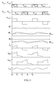
- the power switch diodes S1 and S2 on the primary side undergo driving voltages Vg1 and Vg2 having a phase difference of 180° to form a square wave inverting voltage VAB at the two ends of the primary winding Np.
- Driving voltages of the synchronous rectifiers SR1 and SR2 on the secondary side are respectively Vgs1 and Vgs2, where Vgs1 and Vg2 complement each other, and Vgs2 and Vg1 complement each other. Therefore, a working process of the circuit may be divided into four stages.
- Stage 1 [t0-t1]: The power switch diode S1 on the primary side is turned on and S2 is turned off, and the synchronous rectifier SR1 on the secondary side is turned on and SR2 is turned off.
- a voltage applied on the two ends of the primary winding Np is Vin/2, ⁇ 1 of the first magnetic column 1 where the primary winding is located is increased linearly, and magnetic fluxes ⁇ 2 and ⁇ 3 of other two magnetic columns are increased accordingly.
- a current iSR1 of the first secondary winding Ns1 is equal to a current iout of the second secondary winding Ns2.
- Stage 2 [t1-t2]:
- the power switch diodes S1 and S2 on the primary side are both turned off, and the synchronous rectifiers SR1 and SR2 on the secondary side are both turned on.
- a current ip of the primary winding is zero.
- the first secondary winding Ns1 is shorted by SR1 and SR2, so that voltages of the windings Np and Ns1 wound around the first magnetic column 1 are zero, the magnetic flux ⁇ 1 remains unchanged, and a decrease in the magnetic flux of the second magnetic column 2 is equal to an increment in the magnetic flux of the third magnetic column 3.
- the two synchronous rectifiers on the secondary side are both turned on, a part of the current iSR1 flowing through SR1 is transferred to SR2, and a sum of the currents is equal to iout.
- Stage 3 [t2-t3]: The power switch diode S2 on the primary side is turned on and S1 is turned off, and the synchronous rectifier SR2 on the secondary side is turned on and SR1 is turned off.
- the voltage applied on the two ends of the primary winding Np is -Vin/2, ⁇ 1 of the first magnetic column 1 where the primary winding is located is decreased linearly, and the magnetic fluxes ⁇ 2 and ⁇ 3 of other two magnetic columns are decreased accordingly.
- the current iout of the second secondary winding Ns2 totally flows through the synchronous rectifier SR2.
- Stage 4 [t3-t4]:
- the power switch diodes S1 and S2 on the primary side are both turned off, and the synchronous rectifiers SR1 and SR2 on the secondary side are both turned on.
- the current ip of the primary winding is zero.
- the first secondary winding Ns1 is shorted by SR1 and SR2, so that the voltages of the windings Np and Ns1 wound around the first magnetic column 1 are zero, the magnetic flux ⁇ 1 remains unchanged, and a decrease in the magnetic flux of the second magnetic column 2 is equal to an increment in the magnetic flux of the third magnetic column 3.
- the two synchronous rectifiers on the secondary side are both turned on, a part of the current iSR2 flowing through SR2 is transferred to SR1, and a sum of the currents is equal to iout.
- FIG. 5 shows a magnetic integration half-bridge converter of Embodiment 2.
- an EE-type magnetic core of Embodiment 2 includes three windings and one energy storage air gap.
- a primary winding Np and a first secondary winding Ns1 are wound around a first magnetic column 1
- a second secondary winding Ns2 is wound around a second magnetic column 2
- an energy storage air gap 1 is disposed on a third magnetic column 3
- the number of turns of the first secondary winding Ns1 is twice the number of turns of the second secondary winding Ns2.
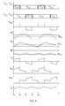
- a working process of the circuit of Embodiment 2 may also be divided into four stages:
- FIG. 7 shows a magnetic integration half-bridge converter of Embodiment 3.
- a third secondary winding Ns3 is added on a third magnetic column 3.
- an EE-type magnetic core of Embodiment 3 includes four windings and one energy storage air gap.
- a primary winding Np and a first secondary winding Ns1 are wound around a first magnetic column 1
- a second secondary winding Ns2 is wound around a second magnetic column 2
- the third winding Ns3 is wound around the third magnetic column 3
- an energy storage air gap 1 is defined in the third magnetic column 3
- the number of turns of the first secondary winding Ns1 is twice the number of turns of the second secondary winding Ns2.
- the first secondary winding Ns1, the second secondary winding Ns2, the third secondary winding Ns3, an output filtering capacitor Co, and a first synchronous rectifier SR1 form a power circuit on the secondary side;
- the second secondary winding Ns2, the third secondary winding Ns3, the output filtering capacitor Co, and a second synchronous rectifier SR2 form another power circuit on the secondary side.
- a series branch of the first synchronous rectifier SR1 and the first secondary winding Ns1 is connected to the second synchronous rectifier SR2 in parallel.
- the second secondary winding Ns2 and the third secondary winding Ns3 are connected in parallel, so as to increase an output filtering inductance.
- a current flowing through the second secondary winding Ns2 and the third secondary winding Ns3 is a sum of currents of the synchronous rectifiers SR1 and SR2.
- FIG. 12 shows a magnetic integration half-bridge converter of Embodiment 4.
- an EE-type magnetic core of Embodiment 4 includes three windings and one energy storage air gap.
- a primary winding Np and a first secondary winding Ns1 are wound around a first magnetic column 1
- a second secondary winding Ns2 is wound around a third magnetic column 3
- an energy storage air gap 1 is disposed on the third magnetic column 3
- the number of turns of the first secondary winding Ns1 is twice the number of turns of the second secondary winding Ns2, and the first secondary winding Ns1 is drawn out of the second secondary winding Ns2.
- a working process of the circuit of Embodiment 4 is the same as that of Embodiment 2.
- the inverter circuit with the double ends symmetrically working is the half-bridge inverter circuit
- the primary winding and the first secondary winding are wound around the same magnetic column, and a synchronous rectifier replaces a rectifier diode in the prior art, thereby reducing a turn-on loss of a switch device, and clamping the voltage of the first secondary winding Ns1 to 0 in stages 2 and 4, so as to play a part in zero voltage drop clamping of the secondary winding.
- least primary windings may be adopted to implement energy transferring from the primary side to the secondary side, thereby reducing a loss of the windings and a leakage inductance of the primary side and the secondary side, and implementing high efficient conversion of energy.
- the inverter circuit with the double ends symmetrically working may also be the full-bridge inverter circuit and the push-pull circuit, for example, a magnetic integration full-bridge inverter in FIG. 8 and a magnetic integration push-pull converter in FIG. 9 .
- windings on the primary side and the secondary side are the same as those of the magnetic integration half-bridge converter in FIG. 2 , FIG. 5 , or FIG. 7 .
- the magnetic integration push-pull converter in FIG. 8 is the same as those of the magnetic integration half-bridge converter in FIG. 2 , FIG. 5 , or FIG. 7 .
- the magnetic integration half-bridge 9 has two primary windings, being respectively Np1 and Np2, that is, has one more primary winding than the full-bridge and the half-bridge, but the primary windings Np1 and Np2 are wound around the same magnetic column, and at the same time, the winding structure on the secondary side is the same as that of the magnetic integration half-bridge inverter. Therefore, the working timing and internal magnetic fluxes ⁇ 1, ⁇ 2, and ⁇ 3 of forming magnetic cores of the magnetic integration full-bridge inverter in FIG. 8 and the magnetic integration push-pull converter in FIG. 9 are respectively the same as those of the magnetic integration half-bridge converter of the present invention.
- a shadow region in FIG. 10 represents a copper sheet of a secondary winding power loop of an E shape with an upward opening and including three parts, where two parts of the copper sheet pass through a magnetic core window and are respectively windings Ns1 and Ns2, the third part is connected to the secondary rectifier SR2 outside the magnetic core and is a trace part.
- the primary winding Np is wound around the first magnetic column 1.
- a part of the primary winding Np is in the same winding window as Ns1; and a part of the primary winding Np is exposed outside the magnetic core window, so as to ensure a good coupling relationship between the part of the primary winding Np and the trace.
- the high efficient energy switching from the primary winding Np to the secondary windings Ns1 and Ns2 can be implemented, and an effective zero voltage drop clamping function of SR1 and SR2 on the secondary windings can be ensured.
- the energy storage air gap of the E-shaped magnetic core is disposed on the second magnetic column 2 and the third magnetic column 3 or is disposed only on the third magnetic column 3, and therefore, in order to more effectively control magnetic field distribution outside the integrated magnetic member, in the magnetic integration double-ended converter provided in the embodiment of the present invention, the primary winding Np and the first secondary winding Ns1 may also be wound around the second magnetic column 2 and the third magnetic column 3 at the same time, and other structures keep the same.
- a shadow region in FIG. 11 represents a copper sheet of a secondary winding power loop of an E shape with an upward opening and including three parts, where two parts of the copper sheet pass through a magnetic core window and are respectively windings Ns1 and Ns2, the third part is connected to the secondary rectifier SR2 outside the magnetic core and is a trace part.
- the primary winding Np is wound around the second magnetic column 2 and the third magnetic column 3.
- a part of the primary winding Np is in the same winding window as Ns1; and a part of the primary winding Np is exposed outside the magnetic core window, so as to ensure a good coupling relationship between the part of the primary winding Np and the trace.
- the difference between FIG. 11 and FIG. 10 is that, the trace part follows the external side of the primary winding Np being wound around the second magnetic column 2, so as to ensure keeping good coupling with the primary part.
- an embodiment of the present invention provides another magnetic integration double-ended converter, which includes:
- the integrated magnetic member having the magnetic core with the three magnetic columns includes three windings and two energy storage air gaps, where the primary winding and the first secondary winding are both wound around the second magnetic column and the third magnetic column, the second secondary winding is wound around the second magnetic column, the total output current flows through the second secondary winding, and the energy storage air gaps are respectively disposed on the second magnetic column and the third magnetic column.
- the number of turns of the first secondary winding and the number of turns of the second secondary winding are not limited and may be the same or different.
- the integrated magnetic member having the magnetic core with the three magnetic columns includes three windings and one energy storage air gap, where the primary winding and the first secondary winding are both wound around the second magnetic column and the third magnetic column, the second secondary winding is wound around the second magnetic column, the total output current flows through the second secondary winding, and the energy storage air gap is disposed only on the third magnetic column.
- the number of turns of the first secondary winding is required to be twice the number of turns of the second secondary winding.
- the integrated magnetic member having the magnetic core with the three magnetic columns includes four windings and one energy storage air gap, where the primary winding and the first secondary winding are both wound around the second magnetic column and the third magnetic column, the second secondary winding is wound around the second magnetic column, the third secondary winding is wound around the third magnetic column, the third secondary winding is connected to the second secondary winding in series, the total output current flows through the third secondary winding and the second secondary winding, and the energy storage air gap is disposed only on the third magnetic column.
- the number of turns of the first secondary winding is also required to be twice the number of turns of the second secondary winding.
- the inverter circuit with the double ends symmetrically working included in the magnetic integration double-ended converter may be any one of the half-bridge inverter circuit, the full-bridge inverter circuit, and the push-pull circuit, and can generate a square wave voltage signal acting on the primary winding.
- the primary winding and the first secondary winding are both wound around the first magnetic column without the energy storage air gap or are both wound around the second magnetic column and the third magnetic column with at least one energy storage air gap disposed, when the first secondary winding and/or the second secondary winding has one turn, the length of the winding is reduced, so the actual requirement is satisfied, and meanwhile, the loss of the winding can be reduced.
- the magnetic integration double-ended converter provided in the embodiment of the present invention may be applicable to a direct current-direct current (DC-DC) secondary power source module as a communication device.
- DC-DC direct current-direct current
Landscapes
- Engineering & Computer Science (AREA)
- Power Engineering (AREA)
- Chemical & Material Sciences (AREA)
- Composite Materials (AREA)
- Dc-Dc Converters (AREA)
- Rectifiers (AREA)
Applications Claiming Priority (4)
| Application Number | Priority Date | Filing Date | Title |
|---|---|---|---|
| CN201010004094A CN101728968A (zh) | 2010-01-19 | 2010-01-19 | 一种磁集成双端变换器 |
| CN201010266511.XA CN101951181B (zh) | 2010-01-19 | 2010-08-30 | 一种磁集成双端变换器 |
| EP11734359.0A EP2512025B1 (de) | 2010-01-19 | 2011-01-18 | Doppelenden-umwandler mit magnetischer integration |
| PCT/CN2011/070353 WO2011088777A1 (zh) | 2010-01-19 | 2011-01-18 | 一种磁集成双端变换器 |
Related Parent Applications (2)
| Application Number | Title | Priority Date | Filing Date |
|---|---|---|---|
| EP11734359.0A Division EP2512025B1 (de) | 2010-01-19 | 2011-01-18 | Doppelenden-umwandler mit magnetischer integration |
| EP11734359.0A Division-Into EP2512025B1 (de) | 2010-01-19 | 2011-01-18 | Doppelenden-umwandler mit magnetischer integration |
Publications (3)
| Publication Number | Publication Date |
|---|---|
| EP2806551A2 true EP2806551A2 (de) | 2014-11-26 |
| EP2806551A3 EP2806551A3 (de) | 2015-09-23 |
| EP2806551B1 EP2806551B1 (de) | 2020-07-22 |
Family
ID=42449353
Family Applications (2)
| Application Number | Title | Priority Date | Filing Date |
|---|---|---|---|
| EP14175172.7A Active EP2806551B1 (de) | 2010-01-19 | 2011-01-18 | Doppelenden-Umwandler mit magnetischer Integration |
| EP11734359.0A Active EP2512025B1 (de) | 2010-01-19 | 2011-01-18 | Doppelenden-umwandler mit magnetischer integration |
Family Applications After (1)
| Application Number | Title | Priority Date | Filing Date |
|---|---|---|---|
| EP11734359.0A Active EP2512025B1 (de) | 2010-01-19 | 2011-01-18 | Doppelenden-umwandler mit magnetischer integration |
Country Status (6)
| Country | Link |
|---|---|
| US (2) | US8848397B2 (de) |
| EP (2) | EP2806551B1 (de) |
| CN (3) | CN101728968A (de) |
| BR (1) | BR112012010900B1 (de) |
| RU (1) | RU2524385C2 (de) |
| WO (1) | WO2011088777A1 (de) |
Families Citing this family (31)
| Publication number | Priority date | Publication date | Assignee | Title |
|---|---|---|---|---|
| CN101728968A (zh) * | 2010-01-19 | 2010-06-09 | 华为技术有限公司 | 一种磁集成双端变换器 |
| WO2013003788A1 (en) * | 2011-06-30 | 2013-01-03 | Analog Devices, Inc. | Isolated power converter with magnetics on chip |
| CN103457454B (zh) | 2013-08-21 | 2016-08-24 | 华为技术有限公司 | 一种电压变换器和共模噪声阻抗调整方法 |
| US20150256087A1 (en) * | 2013-11-07 | 2015-09-10 | Ionel Jitaru | Soft Switching Converter with Dual Transformer by Steering the Magnetizing Current |
| CN104701000B (zh) * | 2013-12-04 | 2018-05-08 | 台达电子企业管理(上海)有限公司 | 集成磁性组件与应用其的全波整流变换器 |
| CN104716837B (zh) * | 2013-12-17 | 2018-06-15 | 通用电气公司 | 升降压变换器和升降压控制方法 |
| CN104752045A (zh) * | 2013-12-30 | 2015-07-01 | 联合汽车电子有限公司 | 一种变压器和电感器的集成结构及其实现方法 |
| JP5983637B2 (ja) * | 2014-01-10 | 2016-09-06 | 株式会社デンソー | トランス装置 |
| WO2015165107A1 (zh) * | 2014-04-30 | 2015-11-05 | 深圳欧陆通电子有限公司 | 一种用电设备及电源装置 |
| FR3025956B1 (fr) * | 2014-09-12 | 2018-03-02 | Valeo Siemens Eautomotive France Sas | Convertisseur de tension continue et procede de commande associe |
| US9876437B2 (en) | 2014-09-26 | 2018-01-23 | Lenovo Enterprise Solutions (Singapore) Pte. Ltd. | Interleaved transformer/inductor |
| EP3157022A1 (de) * | 2015-10-16 | 2017-04-19 | SMA Solar Technology AG | Drosselanordnung und energieversorgungssystem unter verwendung derselben |
| US10277141B2 (en) * | 2016-09-15 | 2019-04-30 | Psemi Corporation | Current protected integrated transformer driver for isolating a DC-DC convertor |
| US10438736B2 (en) | 2016-10-28 | 2019-10-08 | Delta Electronics (Shanghai) Co., Ltd. | Magnetic component and manufacturing method thereof |
| US10242791B2 (en) * | 2016-10-28 | 2019-03-26 | Delta Electronics (Shanghai) Co., Ltd | Coupled-inductor module and voltage regulating module comprising the same |
| US10643782B2 (en) | 2016-10-28 | 2020-05-05 | Delta Electronics (Shanghai) Co., Ltd. | Magnetic component and power module |
| CN106936320B (zh) * | 2017-05-11 | 2024-04-26 | 辽宁工程技术大学 | 一种交错并联磁集成双向全桥llc谐振变换器 |
| CN107731481A (zh) * | 2017-08-23 | 2018-02-23 | 广路智能科技有限公司 | 一种磁路拓扑集成磁体 |
| CN108648899B (zh) * | 2018-03-27 | 2022-02-11 | 华为数字能源技术有限公司 | 一种磁集成器件、变换器、功率因数校正电路及方法 |
| CN108964646B (zh) * | 2018-07-17 | 2022-05-13 | 武昌首义学院 | 一种功能集成的边沿调制igbt/mos驱动系统 |
| CN109067186B (zh) * | 2018-09-14 | 2024-02-13 | 广州金升阳科技有限公司 | 一种改进型输出零纹波变换器及其控制方法 |
| CN109686538B (zh) | 2018-12-11 | 2020-07-28 | 华为技术有限公司 | 一种变压器以及电源 |
| CN109617441B (zh) * | 2019-01-30 | 2024-01-30 | 广州工程技术职业学院 | 三电平半桥型变换器及其换流方法 |
| CN112398345B (zh) * | 2019-08-16 | 2025-02-28 | 杭州展顺科技有限公司 | 一种直流-直流变换器 |
| CN114825317A (zh) | 2021-01-22 | 2022-07-29 | 台达电子企业管理(上海)有限公司 | 光伏储能系统及其控制方法 |
| CN115171997B (zh) * | 2021-04-01 | 2025-12-19 | 台达电子工业股份有限公司 | 功率转换模块及其磁性组件 |
| CN115360919B (zh) * | 2021-04-30 | 2026-01-16 | 台达电子工业股份有限公司 | 功率转换装置 |
| WO2023027594A1 (en) * | 2021-08-25 | 2023-03-02 | Enatel | Zero current sensor for a power converter |
| CN114744882B (zh) * | 2022-04-24 | 2025-11-18 | 西安交通大学 | 一种基于集成矩阵磁芯的隔离型单级dc-dc变换器 |
| CN115001285B (zh) * | 2022-08-01 | 2022-11-04 | 银河航天(西安)科技有限公司 | 一种功率转换电路及功率转换系统 |
| WO2026040050A1 (zh) * | 2024-08-22 | 2026-02-26 | 上海英联电子系统有限公司 | 降压变换器 |
Family Cites Families (20)
| Publication number | Priority date | Publication date | Assignee | Title |
|---|---|---|---|---|
| DK382687A (da) | 1987-07-22 | 1989-04-14 | Scanpower | Stroemforsyningskredsloeb |
| US5555494A (en) * | 1993-09-13 | 1996-09-10 | Morris; George Q. | Magnetically integrated full wave DC to DC converter |
| US5784266A (en) | 1996-06-14 | 1998-07-21 | Virginia Power Technologies, Inc | Single magnetic low loss high frequency converter |
| US6351402B1 (en) | 2000-09-29 | 2002-02-26 | Compaq Information Technologies Group, L.P. | AC adapter with current driven, zero-voltage switched synchronous rectifier |
| US6400249B1 (en) | 2000-12-18 | 2002-06-04 | Ascom Energy Systems Ag | Transformer providing low output voltage |
| US7034647B2 (en) * | 2001-10-12 | 2006-04-25 | Northeastern University | Integrated magnetics for a DC-DC converter with flexible output inductor |
| US6549436B1 (en) * | 2002-02-21 | 2003-04-15 | Innovative Technology Licensing Llc | Integrated magnetic converter circuit and method with improved filtering |
| US6714428B2 (en) | 2002-03-26 | 2004-03-30 | Delta Electronics Inc. | Combined transformer-inductor device for application to DC-to-DC converter with synchronous rectifier |
| CN1571259A (zh) * | 2003-07-17 | 2005-01-26 | 中兴通讯股份有限公司 | 零电压开关脉宽调制全桥变换器的磁集成装置 |
| US7012414B1 (en) * | 2004-08-19 | 2006-03-14 | Coldwatt, Inc. | Vertically packaged switched-mode power converter |
| CN101517878B (zh) * | 2006-10-02 | 2012-02-08 | 株式会社村田制作所 | 双端绝缘型dc-dc转换器 |
| CN201008125Y (zh) * | 2007-01-09 | 2008-01-16 | 南京航空航天大学 | 有源钳位磁集成变换器 |
| CN101030732A (zh) * | 2007-01-09 | 2007-09-05 | 南京航空航天大学 | 输出电流纹波最小化正激式磁集成变换器 |
| JP2008205466A (ja) * | 2007-02-17 | 2008-09-04 | Zhejiang Univ | 磁気部品 |
| CN101257255B (zh) * | 2007-12-25 | 2011-10-12 | 南京航空航天大学 | 用于llc谐振系列拓扑磁集成变换器 |
| KR100983033B1 (ko) * | 2008-03-17 | 2010-09-17 | 삼성전기주식회사 | 집적화된 트랜스포머 및 이를 이용한 전원 장치 |
| US7742318B2 (en) * | 2008-06-10 | 2010-06-22 | Virginia Tech Intellectual Properties, Inc. | Multi-element resonant converters |
| CN101355308B (zh) * | 2008-08-29 | 2010-07-21 | 浙江大学 | 一种磁集成的零电压零电流软开关全桥电路 |
| CN101562404B (zh) * | 2009-05-16 | 2011-12-07 | 旭丽电子(广州)有限公司 | 谐振转换装置及其同步整流电路 |
| CN101728968A (zh) | 2010-01-19 | 2010-06-09 | 华为技术有限公司 | 一种磁集成双端变换器 |
-
2010
- 2010-01-19 CN CN201010004094A patent/CN101728968A/zh active Pending
- 2010-08-30 CN CN201410045276.1A patent/CN103762853B/zh active Active
- 2010-08-30 CN CN201010266511.XA patent/CN101951181B/zh active Active
-
2011
- 2011-01-18 EP EP14175172.7A patent/EP2806551B1/de active Active
- 2011-01-18 WO PCT/CN2011/070353 patent/WO2011088777A1/zh not_active Ceased
- 2011-01-18 RU RU2012124058/07A patent/RU2524385C2/ru active
- 2011-01-18 EP EP11734359.0A patent/EP2512025B1/de active Active
- 2011-01-18 BR BR112012010900-6A patent/BR112012010900B1/pt active IP Right Grant
-
2012
- 2012-04-19 US US13/451,381 patent/US8848397B2/en active Active
-
2014
- 2014-08-22 US US14/466,326 patent/US9160244B2/en active Active
Non-Patent Citations (1)
| Title |
|---|
| None |
Also Published As
| Publication number | Publication date |
|---|---|
| CN101951181B (zh) | 2014-02-19 |
| CN101728968A (zh) | 2010-06-09 |
| EP2806551B1 (de) | 2020-07-22 |
| WO2011088777A1 (zh) | 2011-07-28 |
| US8848397B2 (en) | 2014-09-30 |
| EP2806551A3 (de) | 2015-09-23 |
| BR112012010900B1 (pt) | 2019-11-19 |
| CN103762853B (zh) | 2017-01-25 |
| CN103762853A (zh) | 2014-04-30 |
| EP2512025B1 (de) | 2014-09-10 |
| BR112012010900A2 (pt) | 2016-04-05 |
| EP2512025A1 (de) | 2012-10-17 |
| US20140362607A1 (en) | 2014-12-11 |
| US9160244B2 (en) | 2015-10-13 |
| RU2524385C2 (ru) | 2014-07-27 |
| EP2512025A4 (de) | 2013-08-07 |
| RU2012124058A (ru) | 2013-12-20 |
| CN101951181A (zh) | 2011-01-19 |
| US20120201053A1 (en) | 2012-08-09 |
Similar Documents
| Publication | Publication Date | Title |
|---|---|---|
| EP2806551B1 (de) | Doppelenden-Umwandler mit magnetischer Integration | |
| US8787041B2 (en) | Power converter integrated with flyback converter | |
| EP3905496B1 (de) | Multipegel-wechselrichter und verfahren zur lieferung von multipegelspannungsausgang durch multipegel-wechselrichter | |
| US9413257B2 (en) | Enhanced flyback converter | |
| US6952353B2 (en) | Integrated magnetic isolated two-inductor boost converter | |
| US20150070942A1 (en) | Dc-dc converter | |
| US11664728B2 (en) | Power conversion device | |
| US11527959B2 (en) | Control method of power conversion device | |
| US11646670B2 (en) | Power conversion module | |
| Jin et al. | An improved ZVS PWM three-level converter | |
| JP2020182281A (ja) | 電力変換装置 | |
| US11283360B2 (en) | Converter | |
| US10164542B2 (en) | Electronic converter, and corresponding method for designing a magnetic component | |
| EP4064540A1 (de) | Steuerschaltung, steuerverfahren und stromwandler | |
| KR101444594B1 (ko) | 위상 천이 풀브리지 컨버터 | |
| JP2001218457A (ja) | Dc/dcコンバータ | |
| US11063522B2 (en) | Converter for improving conversion efficiency | |
| JP2016158422A (ja) | フォワード形dc−dcコンバータ回路 | |
| EP4697581A1 (de) | Nichtisolierter vollbrücken-gleichstromwandler | |
| CN119906279A (zh) | 一种针对三相交错独立母线llc的软开关分析方法及系统 | |
| CN116961435A (zh) | 功率变换器 | |
| CN117526713A (zh) | Dc-dc变换器及dc-dc变换装置 | |
| CN102013810A (zh) | 带输出中点的双路双管正激组合变换器 | |
| Jitaru | Signal Transfer Through Power Magnetics |
Legal Events
| Date | Code | Title | Description |
|---|---|---|---|
| PUAI | Public reference made under article 153(3) epc to a published international application that has entered the european phase |
Free format text: ORIGINAL CODE: 0009012 |
|
| 17P | Request for examination filed |
Effective date: 20140701 |
|
| AC | Divisional application: reference to earlier application |
Ref document number: 2512025 Country of ref document: EP Kind code of ref document: P |
|
| AK | Designated contracting states |
Kind code of ref document: A2 Designated state(s): AL AT BE BG CH CY CZ DE DK EE ES FI FR GB GR HR HU IE IS IT LI LT LU LV MC MK MT NL NO PL PT RO RS SE SI SK SM TR |
|
| PUAL | Search report despatched |
Free format text: ORIGINAL CODE: 0009013 |
|
| AK | Designated contracting states |
Kind code of ref document: A3 Designated state(s): AL AT BE BG CH CY CZ DE DK EE ES FI FR GB GR HR HU IE IS IT LI LT LU LV MC MK MT NL NO PL PT RO RS SE SI SK SM TR |
|
| RIC1 | Information provided on ipc code assigned before grant |
Ipc: H02M 3/337 20060101ALI20150819BHEP Ipc: H01F 3/14 20060101ALI20150819BHEP Ipc: H02M 7/48 20070101ALI20150819BHEP Ipc: H01F 27/28 20060101ALI20150819BHEP Ipc: H01F 27/30 20060101ALI20150819BHEP Ipc: H02M 1/00 20070101ALI20150819BHEP Ipc: H02M 3/28 20060101ALI20150819BHEP Ipc: H01F 27/38 20060101ALI20150819BHEP Ipc: H02M 3/335 20060101AFI20150819BHEP |
|
| R17P | Request for examination filed (corrected) |
Effective date: 20160323 |
|
| RBV | Designated contracting states (corrected) |
Designated state(s): AL AT BE BG CH CY CZ DE DK EE ES FI FR GB GR HR HU IE IS IT LI LT LU LV MC MK MT NL NO PL PT RO RS SE SI SK SM TR |
|
| GRAP | Despatch of communication of intention to grant a patent |
Free format text: ORIGINAL CODE: EPIDOSNIGR1 |
|
| STAA | Information on the status of an ep patent application or granted ep patent |
Free format text: STATUS: GRANT OF PATENT IS INTENDED |
|
| INTG | Intention to grant announced |
Effective date: 20200316 |
|
| GRAS | Grant fee paid |
Free format text: ORIGINAL CODE: EPIDOSNIGR3 |
|
| GRAA | (expected) grant |
Free format text: ORIGINAL CODE: 0009210 |
|
| STAA | Information on the status of an ep patent application or granted ep patent |
Free format text: STATUS: THE PATENT HAS BEEN GRANTED |
|
| AC | Divisional application: reference to earlier application |
Ref document number: 2512025 Country of ref document: EP Kind code of ref document: P |
|
| AK | Designated contracting states |
Kind code of ref document: B1 Designated state(s): AL AT BE BG CH CY CZ DE DK EE ES FI FR GB GR HR HU IE IS IT LI LT LU LV MC MK MT NL NO PL PT RO RS SE SI SK SM TR |
|
| REG | Reference to a national code |
Ref country code: GB Ref legal event code: FG4D |
|
| REG | Reference to a national code |
Ref country code: CH Ref legal event code: EP |
|
| REG | Reference to a national code |
Ref country code: DE Ref legal event code: R096 Ref document number: 602011067938 Country of ref document: DE |
|
| REG | Reference to a national code |
Ref country code: AT Ref legal event code: REF Ref document number: 1294330 Country of ref document: AT Kind code of ref document: T Effective date: 20200815 |
|
| REG | Reference to a national code |
Ref country code: IE Ref legal event code: FG4D |
|
| REG | Reference to a national code |
Ref country code: LT Ref legal event code: MG4D |
|
| REG | Reference to a national code |
Ref country code: AT Ref legal event code: MK05 Ref document number: 1294330 Country of ref document: AT Kind code of ref document: T Effective date: 20200722 |
|
| PG25 | Lapsed in a contracting state [announced via postgrant information from national office to epo] |
Ref country code: ES Free format text: LAPSE BECAUSE OF FAILURE TO SUBMIT A TRANSLATION OF THE DESCRIPTION OR TO PAY THE FEE WITHIN THE PRESCRIBED TIME-LIMIT Effective date: 20200722 Ref country code: LT Free format text: LAPSE BECAUSE OF FAILURE TO SUBMIT A TRANSLATION OF THE DESCRIPTION OR TO PAY THE FEE WITHIN THE PRESCRIBED TIME-LIMIT Effective date: 20200722 Ref country code: PT Free format text: LAPSE BECAUSE OF FAILURE TO SUBMIT A TRANSLATION OF THE DESCRIPTION OR TO PAY THE FEE WITHIN THE PRESCRIBED TIME-LIMIT Effective date: 20201123 Ref country code: HR Free format text: LAPSE BECAUSE OF FAILURE TO SUBMIT A TRANSLATION OF THE DESCRIPTION OR TO PAY THE FEE WITHIN THE PRESCRIBED TIME-LIMIT Effective date: 20200722 Ref country code: BG Free format text: LAPSE BECAUSE OF FAILURE TO SUBMIT A TRANSLATION OF THE DESCRIPTION OR TO PAY THE FEE WITHIN THE PRESCRIBED TIME-LIMIT Effective date: 20201022 Ref country code: NO Free format text: LAPSE BECAUSE OF FAILURE TO SUBMIT A TRANSLATION OF THE DESCRIPTION OR TO PAY THE FEE WITHIN THE PRESCRIBED TIME-LIMIT Effective date: 20201022 Ref country code: AT Free format text: LAPSE BECAUSE OF FAILURE TO SUBMIT A TRANSLATION OF THE DESCRIPTION OR TO PAY THE FEE WITHIN THE PRESCRIBED TIME-LIMIT Effective date: 20200722 Ref country code: SE Free format text: LAPSE BECAUSE OF FAILURE TO SUBMIT A TRANSLATION OF THE DESCRIPTION OR TO PAY THE FEE WITHIN THE PRESCRIBED TIME-LIMIT Effective date: 20200722 Ref country code: GR Free format text: LAPSE BECAUSE OF FAILURE TO SUBMIT A TRANSLATION OF THE DESCRIPTION OR TO PAY THE FEE WITHIN THE PRESCRIBED TIME-LIMIT Effective date: 20201023 Ref country code: FI Free format text: LAPSE BECAUSE OF FAILURE TO SUBMIT A TRANSLATION OF THE DESCRIPTION OR TO PAY THE FEE WITHIN THE PRESCRIBED TIME-LIMIT Effective date: 20200722 |
|
| PG25 | Lapsed in a contracting state [announced via postgrant information from national office to epo] |
Ref country code: IS Free format text: LAPSE BECAUSE OF FAILURE TO SUBMIT A TRANSLATION OF THE DESCRIPTION OR TO PAY THE FEE WITHIN THE PRESCRIBED TIME-LIMIT Effective date: 20201122 Ref country code: RS Free format text: LAPSE BECAUSE OF FAILURE TO SUBMIT A TRANSLATION OF THE DESCRIPTION OR TO PAY THE FEE WITHIN THE PRESCRIBED TIME-LIMIT Effective date: 20200722 Ref country code: LV Free format text: LAPSE BECAUSE OF FAILURE TO SUBMIT A TRANSLATION OF THE DESCRIPTION OR TO PAY THE FEE WITHIN THE PRESCRIBED TIME-LIMIT Effective date: 20200722 Ref country code: PL Free format text: LAPSE BECAUSE OF FAILURE TO SUBMIT A TRANSLATION OF THE DESCRIPTION OR TO PAY THE FEE WITHIN THE PRESCRIBED TIME-LIMIT Effective date: 20200722 |
|
| PG25 | Lapsed in a contracting state [announced via postgrant information from national office to epo] |
Ref country code: NL Free format text: LAPSE BECAUSE OF FAILURE TO SUBMIT A TRANSLATION OF THE DESCRIPTION OR TO PAY THE FEE WITHIN THE PRESCRIBED TIME-LIMIT Effective date: 20200722 |
|
| REG | Reference to a national code |
Ref country code: DE Ref legal event code: R097 Ref document number: 602011067938 Country of ref document: DE |
|
| PG25 | Lapsed in a contracting state [announced via postgrant information from national office to epo] |
Ref country code: CZ Free format text: LAPSE BECAUSE OF FAILURE TO SUBMIT A TRANSLATION OF THE DESCRIPTION OR TO PAY THE FEE WITHIN THE PRESCRIBED TIME-LIMIT Effective date: 20200722 Ref country code: EE Free format text: LAPSE BECAUSE OF FAILURE TO SUBMIT A TRANSLATION OF THE DESCRIPTION OR TO PAY THE FEE WITHIN THE PRESCRIBED TIME-LIMIT Effective date: 20200722 Ref country code: DK Free format text: LAPSE BECAUSE OF FAILURE TO SUBMIT A TRANSLATION OF THE DESCRIPTION OR TO PAY THE FEE WITHIN THE PRESCRIBED TIME-LIMIT Effective date: 20200722 Ref country code: IT Free format text: LAPSE BECAUSE OF FAILURE TO SUBMIT A TRANSLATION OF THE DESCRIPTION OR TO PAY THE FEE WITHIN THE PRESCRIBED TIME-LIMIT Effective date: 20200722 Ref country code: RO Free format text: LAPSE BECAUSE OF FAILURE TO SUBMIT A TRANSLATION OF THE DESCRIPTION OR TO PAY THE FEE WITHIN THE PRESCRIBED TIME-LIMIT Effective date: 20200722 Ref country code: SM Free format text: LAPSE BECAUSE OF FAILURE TO SUBMIT A TRANSLATION OF THE DESCRIPTION OR TO PAY THE FEE WITHIN THE PRESCRIBED TIME-LIMIT Effective date: 20200722 |
|
| PLBE | No opposition filed within time limit |
Free format text: ORIGINAL CODE: 0009261 |
|
| STAA | Information on the status of an ep patent application or granted ep patent |
Free format text: STATUS: NO OPPOSITION FILED WITHIN TIME LIMIT |
|
| PG25 | Lapsed in a contracting state [announced via postgrant information from national office to epo] |
Ref country code: AL Free format text: LAPSE BECAUSE OF FAILURE TO SUBMIT A TRANSLATION OF THE DESCRIPTION OR TO PAY THE FEE WITHIN THE PRESCRIBED TIME-LIMIT Effective date: 20200722 |
|
| 26N | No opposition filed |
Effective date: 20210423 |
|
| PG25 | Lapsed in a contracting state [announced via postgrant information from national office to epo] |
Ref country code: SK Free format text: LAPSE BECAUSE OF FAILURE TO SUBMIT A TRANSLATION OF THE DESCRIPTION OR TO PAY THE FEE WITHIN THE PRESCRIBED TIME-LIMIT Effective date: 20200722 |
|
| PG25 | Lapsed in a contracting state [announced via postgrant information from national office to epo] |
Ref country code: SI Free format text: LAPSE BECAUSE OF FAILURE TO SUBMIT A TRANSLATION OF THE DESCRIPTION OR TO PAY THE FEE WITHIN THE PRESCRIBED TIME-LIMIT Effective date: 20200722 Ref country code: MC Free format text: LAPSE BECAUSE OF FAILURE TO SUBMIT A TRANSLATION OF THE DESCRIPTION OR TO PAY THE FEE WITHIN THE PRESCRIBED TIME-LIMIT Effective date: 20200722 |
|
| REG | Reference to a national code |
Ref country code: CH Ref legal event code: PL |
|
| PG25 | Lapsed in a contracting state [announced via postgrant information from national office to epo] |
Ref country code: LU Free format text: LAPSE BECAUSE OF NON-PAYMENT OF DUE FEES Effective date: 20210118 |
|
| REG | Reference to a national code |
Ref country code: BE Ref legal event code: MM Effective date: 20210131 Ref country code: NL Ref legal event code: MP Effective date: 20200722 |
|
| PG25 | Lapsed in a contracting state [announced via postgrant information from national office to epo] |
Ref country code: LI Free format text: LAPSE BECAUSE OF NON-PAYMENT OF DUE FEES Effective date: 20210131 Ref country code: CH Free format text: LAPSE BECAUSE OF NON-PAYMENT OF DUE FEES Effective date: 20210131 |
|
| PG25 | Lapsed in a contracting state [announced via postgrant information from national office to epo] |
Ref country code: IE Free format text: LAPSE BECAUSE OF NON-PAYMENT OF DUE FEES Effective date: 20210118 |
|
| PG25 | Lapsed in a contracting state [announced via postgrant information from national office to epo] |
Ref country code: BE Free format text: LAPSE BECAUSE OF NON-PAYMENT OF DUE FEES Effective date: 20210131 |
|
| PG25 | Lapsed in a contracting state [announced via postgrant information from national office to epo] |
Ref country code: HU Free format text: LAPSE BECAUSE OF FAILURE TO SUBMIT A TRANSLATION OF THE DESCRIPTION OR TO PAY THE FEE WITHIN THE PRESCRIBED TIME-LIMIT; INVALID AB INITIO Effective date: 20110118 Ref country code: CY Free format text: LAPSE BECAUSE OF FAILURE TO SUBMIT A TRANSLATION OF THE DESCRIPTION OR TO PAY THE FEE WITHIN THE PRESCRIBED TIME-LIMIT Effective date: 20200722 |
|
| P01 | Opt-out of the competence of the unified patent court (upc) registered |
Effective date: 20230524 |
|
| PG25 | Lapsed in a contracting state [announced via postgrant information from national office to epo] |
Ref country code: MK Free format text: LAPSE BECAUSE OF FAILURE TO SUBMIT A TRANSLATION OF THE DESCRIPTION OR TO PAY THE FEE WITHIN THE PRESCRIBED TIME-LIMIT Effective date: 20200722 |
|
| PG25 | Lapsed in a contracting state [announced via postgrant information from national office to epo] |
Ref country code: MT Free format text: LAPSE BECAUSE OF FAILURE TO SUBMIT A TRANSLATION OF THE DESCRIPTION OR TO PAY THE FEE WITHIN THE PRESCRIBED TIME-LIMIT Effective date: 20200722 |
|
| PG25 | Lapsed in a contracting state [announced via postgrant information from national office to epo] |
Ref country code: TR Free format text: LAPSE BECAUSE OF FAILURE TO SUBMIT A TRANSLATION OF THE DESCRIPTION OR TO PAY THE FEE WITHIN THE PRESCRIBED TIME-LIMIT Effective date: 20200722 |
|
| PGFP | Annual fee paid to national office [announced via postgrant information from national office to epo] |
Ref country code: GB Payment date: 20251204 Year of fee payment: 16 |
|
| PGFP | Annual fee paid to national office [announced via postgrant information from national office to epo] |
Ref country code: FR Payment date: 20251208 Year of fee payment: 16 |
|
| PGFP | Annual fee paid to national office [announced via postgrant information from national office to epo] |
Ref country code: DE Payment date: 20251203 Year of fee payment: 16 |