EP2806582A1 - Méthode d'inhibition d'alarme et dispositif de réseau optique - Google Patents
Méthode d'inhibition d'alarme et dispositif de réseau optique Download PDFInfo
- Publication number
- EP2806582A1 EP2806582A1 EP13872415.8A EP13872415A EP2806582A1 EP 2806582 A1 EP2806582 A1 EP 2806582A1 EP 13872415 A EP13872415 A EP 13872415A EP 2806582 A1 EP2806582 A1 EP 2806582A1
- Authority
- EP
- European Patent Office
- Prior art keywords
- fault
- indication
- signal
- network device
- station
- Prior art date
- Legal status (The legal status is an assumption and is not a legal conclusion. Google has not performed a legal analysis and makes no representation as to the accuracy of the status listed.)
- Granted
Links
- 230000003287 optical effect Effects 0.000 title claims abstract description 389
- 238000000034 method Methods 0.000 title claims abstract description 42
- 230000005764 inhibitory process Effects 0.000 title 1
- 238000011144 upstream manufacturing Methods 0.000 claims abstract description 63
- 230000001629 suppression Effects 0.000 claims abstract description 20
- 230000005540 biological transmission Effects 0.000 claims description 48
- 230000007547 defect Effects 0.000 claims description 18
- 238000010586 diagram Methods 0.000 description 15
- 230000000694 effects Effects 0.000 description 4
- 238000012546 transfer Methods 0.000 description 4
- 239000000835 fiber Substances 0.000 description 2
- 239000013307 optical fiber Substances 0.000 description 2
- 238000005516 engineering process Methods 0.000 description 1
- 238000012986 modification Methods 0.000 description 1
- 230000004048 modification Effects 0.000 description 1
- 238000012544 monitoring process Methods 0.000 description 1
- 230000008054 signal transmission Effects 0.000 description 1
Images


Classifications
-
- H—ELECTRICITY
- H04—ELECTRIC COMMUNICATION TECHNIQUE
- H04J—MULTIPLEX COMMUNICATION
- H04J14/00—Optical multiplex systems
- H04J14/02—Wavelength-division multiplex systems
- H04J14/0227—Operation, administration, maintenance or provisioning [OAMP] of WDM networks, e.g. media access, routing or wavelength allocation
- H04J14/0254—Optical medium access
- H04J14/0272—Transmission of OAMP information
- H04J14/0275—Transmission of OAMP information using an optical service channel
-
- H—ELECTRICITY
- H04—ELECTRIC COMMUNICATION TECHNIQUE
- H04J—MULTIPLEX COMMUNICATION
- H04J14/00—Optical multiplex systems
- H04J14/02—Wavelength-division multiplex systems
- H04J14/0201—Add-and-drop multiplexing
- H04J14/0202—Arrangements therefor
- H04J14/0213—Groups of channels or wave bands arrangements
-
- H—ELECTRICITY
- H04—ELECTRIC COMMUNICATION TECHNIQUE
- H04J—MULTIPLEX COMMUNICATION
- H04J14/00—Optical multiplex systems
- H04J14/02—Wavelength-division multiplex systems
- H04J14/0287—Protection in WDM systems
-
- H—ELECTRICITY
- H04—ELECTRIC COMMUNICATION TECHNIQUE
- H04B—TRANSMISSION
- H04B2210/00—Indexing scheme relating to optical transmission systems
- H04B2210/07—Monitoring an optical transmission system using a supervisory signal
- H04B2210/071—Monitoring an optical transmission system using a supervisory signal using alarms
Definitions
- Embodiments of the present invention relate to communications technologies, and in particular, to a method for alarm suppression and an optical network device.
- FIG. 1 is a schematic diagram of an optical transfer network scenario.
- Optical network devices in FIG. 1 are optical add-drop multiplexers (Optical Add-Drop Multiplexer, OADM for short).
- OADM Optical Add-Drop Multiplexer
- OADM 1 is configured to send a signal of wavelengths 1 to 40 to OADM 2
- OADM 5 is configured to send a signal of wavelengths 41 to 50 to OADM 2
- OADM 2 is configured to receive the signal of the wavelengths 1 to 40 of OADM 1 and the signal of the wavelengths 41 to 50 of OADM 5
- OADM 2 is further configured to send a signal of wavelengths 1 to 50 to OADM 3
- OADM 4 is configured to receive the signal of the wavelengths 1 to 40 sent by OADM 3; and other OADMs are configured similarly, which is not described herein.
- An OADM when detecting that the signal of all wavelengths configured for a downstream neighbor OADM are faulty, generates optical multiplex section-payload missing indication (Optical Multiplex Section-Payload Missing Indication, OMS-PMI), and sends the generated OMS-PMI to the downstream neighbor OADM; an OADM, when detecting that the signal of all wavelengths configured for a neighbor OADM are faulty but receiving no OMS-PMI sent by an upstream optical network device, reports an LOS alarm to a network management system.
- OMS-PMI optical multiplex Section-payload Missing Indication
- OADM 2 detects that the signal of the wavelengths 1 to 40 of OADM 1 configured to be received is faulty and receives no OMS-PMI sent by OADM 1. Therefore, OADM 2 reports an LOS alarm to a network management system. Moreover, because not all the signals of wavelengths 1 to 50 that OADM 2 are configured to send to OADM 3 are faulty, OADM 2 does not send an OMSPMI to OADM 3. However, OADM 3 detects that the signals of wavelengths 1 to 40 that are configured to send to OADM 4 are faulty and receives no OMS-PMI sent by OADM 2. Therefore, OADM 3 also reports an LOS alarm to the network management system.
- Embodiments of the present invention provide a method for alarm suppression and an optical network device to solve the problem where upstream and downstream optical network devices report an LOS alarm regarding the same fault repeatedly to a network management system.
- an embodiment of the present invention provides a method for alarm suppression, including:
- the fault indication is inter-station signal failure indication, intra-station signal failure indication, or optical channel disconnection indication
- the method further includes:
- the fault indication includes a fault location
- the method further includes:
- the fault indication is optical channel-forward defect indication-payload (Och-FDI-P) state information or optical channel-open connection indication (Och-OCI) state information.
- an embodiment of the present invention provides a method for alarm suppression, including:
- the fault indication is inter-station signal failure indication, intra-station signal failure indication, or optical channel disconnection indication; and the generating the fault indication of the fault signal when the signal is faulty includes:
- the optical channel fault indication includes a local location.
- the fault indication is optical channel-forward defect indication-payload (Och-FDI-P) state information or optical channel-open connection indication (Och-OCI) state information.
- the method further includes:
- an embodiment of the present invention provides an optical network device, including:
- the fault indication is inter-station signal failure indication, intra-station signal failure indication, or optical channel disconnection indication; the controlling unit is further configured to determine a fault type of the fault signal as an inter-station line fault when the fault indication is the inter-station signal failure indication; the controlling unit is further configured to determine the fault type of the fault signal as an intra-station fault when the fault indication is the intra-station signal failure indication; and the controlling unit is further configured to determine the fault type of the fault signal as an optical channel disconnection fault when the fault indication is the optical channel disconnection indication.
- the optical channel fault indication includes a fault location
- the controlling unit is further configured to obtain a fault location of the fault signal corresponding to the fault indication according to the fault location in the fault indication.
- the fault indication is optical channel-forward defect indication-payload (Och-FDI-P) state information or optical channel-open connection indication (Och-OCI) state information.
- an optical network device including:
- the fault indication is inter-station signal failure indication, intra-station signal failure indication, or optical channel disconnection indication;
- the controlling unit is further configured to generate the inter-station signal failure indication when a signal inlet unit detects that the signal fails, where the inter-station signal failure indication includes a wavelength of the failed signal, so that the downstream optical network device determines, according to the inter-station signal failure indication, a fault type of the fault signal as an inter-station line fault;
- the controlling unit is further configured to generate the intra-station signal failure indication when the signal inlet unit detects no signal failure and another unit on a transmission path of the signal detects that the signal fails, where the intra-station signal failure indication includes a wavelength of the failed signal so that the downstream optical network device determines, according to the intra-station signal failure indication, the fault type the fault signal as an intra-station fault;
- the controlling unit is further configured to generate the optical channel disconnection indication when any unit on the transmission path of the signal detects that no optical channel corresponding to the wavelength of
- the fault indication includes a local location.
- the fault indication is optical channel-forward defect indication-payload (Och-FDI-P) state information or optical channel-open connection indication (Och-OCI) state information.
- the sending unit is further configured to send the fault indication to an upstream optical network device of the fault signal after the controlling unit generates the fault indication.
- an embodiment of the present invention provides an optical network device, including:
- the fault indication is inter-station signal failure indication, intra-station signal failure indication, or optical channel disconnection indication; the controller is further configured to determine a fault type of the fault signal as an inter-station line fault when the fault indication is the inter-station signal failure indication; the controller is further configured to determine the fault type of the fault signal as an intra-station fault when the fault indication is the intra-station signal failure indication; and the controller is further configured to determine the fault type of the fault signal as an optical channel disconnection fault when the fault indication is the optical channel disconnection indication.
- the fault indication includes a fault location
- the controller is further configured to obtain a fault location of the fault signal corresponding to the fault indication according to the fault location in the fault indication.
- the fault indication is optical channel-forward defect indication-payload (Och-FDI-P) state information or optical channel-open connection indication (Och-OCI) state information.
- an embodiment of the present invention provides an optical network device, including:
- the fault indication is inter-station signal failure indication, intra-station signal failure indication, or optical channel disconnection indication;
- the controller is further configured to generate the inter-station signal failure indication when a signal inlet unit detects that the signal fails, where the inter-station signal failure indication includes a wavelength of the failed signal, so that the downstream optical network device determines, according to the inter-station signal failure indication, a fault type of the fault signal as an inter-station line fault;
- the controller is further configured to generate the intra-station signal failure indication when the signal inlet unit detects no signal failure and another unit on a transmission path of the signal detects that the signal fails, where the intra-station signal failure indication includes a wavelength of the failed signal so that the downstream optical network device determines, according to the intra-station signal failure indication, the fault type the fault signal as an intra-station fault; and the controller is further configured to generate the optical channel disconnection indication when any unit on the transmission path of the signal detects that no optical channel corresponding to the wavelength of the signal is
- the fault indication includes a local location.
- the fault indication is optical channel-forward defect indication-payload (Och-FDI-P) state information or optical channel-open connection indication (Och-OCI) state information.
- the sender is further configured to send the fault indication to an upstream optical network device of the fault signal after the controller generates the fault indication.
- fault indication of a fault signal sent by an upstream optical network device is received by using an optical supervisory channel; a wavelength of all received signals corresponding to an LOS alarm is determined; whether the wavelength of the fault signal includes the wavelength of all the received signals corresponding to the LOS alarm is determined; and if yes, the LOS alarm is suppressed.
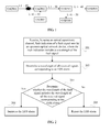
- FIG. 2 is a schematic flowchart of a method for alarm suppression according to a first embodiment of the present invention. This embodiment is described by using a downstream optical network device as an executor. As shown in FIG. 2 , the method according to this embodiment includes:
- an optical channel is used to transfer an optical signal
- an optical supervisory channel is used to perform state monitoring on optical channels and transfer state information of the optical channels.
- the state information is, for example, fault indication.
- An upstream optical network device generates fault indication of a fault signal when determining that a signal is faulty, where the faulty signal indicates that an optical signal configured to be received is not received, or no optical channel corresponding to an optical signal to be sent is configured.
- an optical signal to be received or to be sent needs to be configured for optical transmission units in a network device, and an optical channel needs to be configured for the optical signal to be sent, where the optical transmission units refers to units on an internal transmission path of the optical network device of the optical signal, for example, a fiber line interface unit (Fiber line Interface Unit, FIU for short), a demultiplexer (demultiplexer, DMUX for short), a multiplexer (Multiplexer, MUX), and the like.
- FIU Fiber line Interface Unit
- DMUX demultiplexer
- Multiplexer MUX
- any optical transmission unit in a downstream optical network device when detecting an LOS, may send an LOS alarm to a controlling unit in the same device; and the controlling unit determines, according to an optical signal to be received configured by the optical transmission unit, a wavelength of all received signals corresponding to the LOS alarm.
- a wavelength of a fault signal includes wavelengths 1 to 10; if a wavelength of all received signals corresponding to an LOS alarm includes wavelengths 2 to 5, it may be determined that the wavelength of the fault signal includes the wavelength of all the received signals corresponding to the LOS alarm. If the wavelength of all the received signals corresponding to the LOS alarm includes wavelengths 2 to 15, it may be determined that the wavelength of the fault signal does not include the wavelength of all the received signals corresponding to the LOS alarm.
- the upstream optical network device When the wavelength of the received fault signal sent by the upstream optical network device includes the wavelength of all the received signals corresponding to the LOS alarm, it indicates that the upstream optical network device detected the fault that causes the optical transmission unit to send the LOS alarm, and reported the LOS alarm to the network management system; therefore, the downstream optical network device suppress reporting the LOS alarm to the network management system.
- the downstream optical network device reports the LOS alarm to the network management system, so that the network management system handles in time the fault in optical network transmission according to the reported LOS alarm.
- the downstream optical network device in this embodiment may be an OADM or an optical line amplifier (Optical Line Amplifier, OLA for short).
- OLA optical Line Amplifier
- the fault indication of the fault signal sent by the upstream optical network device is received by using the optical supervisory channel, where the fault indication includes the wavelength of the fault signal; the wavelength of all the received signals corresponding to the LOS alarm is determined; whether the wavelength of the fault signal includes the wavelength of all the received signals corresponding to the LOS alarm is determined, and if yes, the LOS alarm is suppressed.
- FIG. 3 is a schematic flowchart of a method for alarm suppression according to a second embodiment of the present invention. This embodiment is described by using an upstream optical network device as an executor. As shown in FIG. 3 , steps of this embodiment include:
- an upstream optical network device generates, when determining that a signal is faulty, fault indication of the fault signal, where the faulty signal indicates that an optical signal configured to be received is not received, or no optical channel is configured for an optical signal to be sent.
- the signal fault generally is caused by an optical channel fault.
- a signal fault is caused when an optical fiber is disconnected, an optical transmission unit on an optical channel is faulty, or no optical channel is configured for a corresponding wavelength.
- the upstream optical network device when determining that the signal is faulty, sends an LOS alarm to a controlling unit, and the controlling unit reports the LOS alarm to a network management system.
- the upstream optical network device after generating the fault indication of the fault signal, sends the fault indication of the fault signal to a downstream optical network device of the fault signal by using an optical supervisory channel, so that a controlling unit of the downstream optical network device determines, according to the fault indication of the fault signal, whether to suppress the LOS alarm.
- the fault indication of the fault signal generated by the upstream optical network device may also be used by another optical transmission unit on an internal transmission path of the upstream optical network device of the fault signal to suppress the LOS alarm.
- the upstream optical network device may be any optical transport network device that can generate fault indication, for example, an OADM or an OLA.
- the present invention sets no limit thereto.
- the upstream optical network device generates the fault indication of the fault signal when determining that the signal is faulty, where the fault indication includes the wavelength of the fault signal; and sends the fault indication to the downstream optical network device of the fault signal by using the optical supervisory channel, so that the downstream optical network device determines, according to the fault indication of the fault signal, whether to suppress the LOS alarm.
- the fault indication is optical channel-forward defect indicator-payload (Optical Channel-Forward Defect Indicator-Payload, Och-FDI-P for short) state signal, or Optical channel-open connection indication (Optical Channel-Open Connection Indication, Och-OCI for short) state information.
- the fault indication according to the embodiment may be existing Och-FDI-P state information or Och-OCI state information.
- the fault indication may further include the following indication for identifying a fault type, which respectively is inter-station signal failure indication, intra-station signal failure indication, or optical channel disconnection indication.
- the upstream optical network device generates the inter-station signal failure indication when a signal inlet unit detects that the signal fails, where the inter-station signal failure indication includes a wavelength of the failed signal, and the inter-station signal failure indication is used to represent a signal failure state caused by a line fault between optical network devices.
- the inlet unit refers to a first optical transmission unit where an optical signal enters the optical network device, which generally is an FIU.
- the downstream optical network device determines the fault type of the fault signal as an inter-station line fault according to the inter-station signal failure indication.
- the upstream optical network device generates the intra-station signal failure indication when the signal inlet unit detects no signal failure and another unit on the signal transmission path detects that the signal fails, where the intra-station signal failure indication includes the wavelength of the failed signal, and the intra-station signal failure indication is used to represent a signal failure state caused by a fault of an optical transmission unit or a line inside the optical network device on a transmission path of the signal.
- the downstream optical network device determines the fault type of the fault signal as an intra-station fault according to the intra-station signal failure indication.
- the upstream optical network device generates the optical channel disconnection indication when any unit on the transmission path of the signal detects that no optical channel corresponding to the wavelength of the signal is configured, where the optical channel disconnection indication includes the wavelength of the signal for which no optical channel is configured, so that the downstream optical network device determines, according to the optical channel disconnection indication information, a fault type of the fault signal as an optical channel disconnection fault.
- the fault indication includes a fault location.
- the downstream optical network device may obtain a location of a fault point of the fault signal of the fault indication according to the fault location.
- the Och-FDI-P or Och-OCI state information may be improved, where the fault type and fault location are added to an overhead byte of the Och-FDI-P or Och-OCI state information, so as to form the fault indication in the embodiment of the present invention to send to the downstream optical network device by using the optical supervisory channel.
- the fault type and fault location may also be added to an overhead byte of other information, so as to form the fault indication according to the embodiment of the present invention to send to the downstream optical network device by using the optical supervisory channel.
- the fault type and fault location of the fault signal may be individually sent to the downstream optical network device by using the optical supervisory channel.
- the present invention sets no limit to a mode for an optical channel to send the fault type and fault location to the downstream optical network device.
- Table 1 Definition of fault indication Wavelength No. Fault Type Fault Location Such as 1, 2, and 3 Such as intra-station signal failure, intra-station signal failure, or optical channel disconnection Location information of a fault point
- the upstream optical network device after generating the fault indication of the fault signal, the upstream optical network device further sends the fault indication to an upstream optical network device of the fault signal, so that the upstream optical network device of the fault signal obtains the fault type and fault location according to the received fault indication.
- a definition of a forward and backward state may be added to the fault indication.
- An optical network device receiving the fault indication may determine, according to the forward and backward state indication, whether the optical network device sending the fault indication is an upstream optical network device; when the forward and backward state in the received fault indication is a forward state, it indicates that the optical network device sending the fault indication is an upstream optical network device, and the LOS alarm may be suppressed according to the received fault indication.
- FIG. 4 is a schematic diagram illustrating a scenario to which a method for alarm suppression according to a third embodiment of the present invention is applicable.
- an OADM is used as an upstream optical network device and a downstream optical network device as an example.
- OADM 1 is configured to send a signal of wavelengths 1 to 5 to OADM 2;
- OADM 5 is configured to send a signal of wavelengths 6 to 7 to OADM 2;
- OADM 2 is configured to send a signal of wavelengths 1 to 7 to OADM 3;
- OADM 3 is configured to send a signal of wavelengths 1 to 3 and 7 to OADM 4; and
- OADM 3 is configured to send a signal of wavelengths 4 to 6 to OADM 6, where a line fault occurs between OADM 1 and OADM 2, and therefore OADM 2 cannot receive the signal of the wavelengths 1 to 5 sent by OADM 1; and OADM 5 is not configured with an optical channel for the wavelength 7.
- FIG. 4 illustrates a structure of internal optical transmission units of OADM 3.
- an inlet unit is FIU 1, and other units on the transmission path are DMUX 1, DMUX 2, MUX 2, and FIU 2.
- an inlet unit is FIU 1, and other units on the transmission path are DMUX 1, DMUX 3, MUX 3, and FIU 3.
- FIG. 5 is a schematic flowchart of a method for alarm suppression according to a third embodiment of the present invention.
- FIG. 5 is described by using an application scenario illustrated in FIG. 4 as an example, as shown in FIG. 5 :
- OADM 5 Because no optical channel for the wavelength 7 is configured on OADM 5, OADM 5 generates the fault indication of the signal of the wavelength 7, where the fault indication is used to indicate that a fault type of the signal of the wavelength 7 of the signal of the wavelength 7 is optical channel disconnection, and indicate that a fault location of the signal of the wavelength 7 is a local location; and sends the fault indication to OADM 2 by using an optical supervisory channel.
- the fault indication of the signal of the wavelength 7 further includes forward state indication; OADM 2, upon receiving the fault indication, determines, according to the forward state indication, that the fault indication is sent by an upstream optical network device, and may suppress an LOS alarm according to the fault indication.
- the fault indication of the signal of the wavelength 7 sent by OADM 5 to OADM 2 may be illustrated in Table 2: Table 2: Fault indication of the signal of the wavelength 7 sent by OADM 5 to OADM 2 Wavelength No. Fault Type Fault Location Forward and Backward State 7 Optical channel disconnection OADM 5 Forward state
- an inlet unit of OADM 2 detects that the signal of the wavelengths 1 to 5 is faulty, and reports an LOS alarm to a controlling unit (not shown) of OADM 2. Because a receiving unit of OADM 2 receives no corresponding fault indication containing the signal of the wavelengths 1 to 5, OADM 2 reports an alarm to a network management system, and generates fault indication corresponding to the signal of the wavelengths 1 to 5. OADM 2 sends to OADM 3 the locally generated fault indication corresponding to the signal of the wavelengths 1 to 5, and the received fault indication sent by OADM 5 corresponding to the signal of the wavelength 7.
- OADM 2 sends to the OADM 1 the locally generated fault indication corresponding to the signal of the wavelengths 1 to 5.
- the fault indication corresponding to the signal of the wavelengths 1 to 5 and the signal of the wavelength 7 respectively includes the fault type and fault location of the signal of respective wavelengths corresponding to wavelengths 1 to 5 and 7.
- the fault indication of the signal of the wavelengths 1 to 5 and the signal of the wavelength 7 sent by OADM 2 to OADM 3 further includes forward state indication.
- the OADM 3 determines, according to the forward state indication, that the fault indication is sent by an upstream optical network device, so as to suppress the LOS alarm according to the fault indication.
- the fault indication of the signal of the wavelengths 1 to 5 sent by OADM 2 to OADM 1 further includes backward state indication.
- the OADM 1 determines, according to the backward state indication, that the fault indication is sent by a downstream optical network device, and does not suppress the LOS alarm according to the fault indication.
- the fault indication of the signal of the wavelengths 1 to 5 and the signal of the wavelength 7 sent by OADM 2 to OADM 3 may be illustrated in Table 3: Table 3: Fault indication of the signal of the wavelengths 1 to 5 and the signal of the wavelength 7 sent by OADM 2 to OADM 3 Wavelength No. Fault Type Fault Location Forward and Backward State 1 Inter-station signal failure OADM 2 Forward state 2 Inter-station signal failure OADM 2 Forward state 3 Inter-station signal failure OADM 2 Forward state 4 Inter-station signal failure OADM 2 Forward state 5 Inter-station signal failure OADM 2 Forward state 7 Optical channel disconnection OADM 5 Forward state
- the fault indication of the signal of the wavelengths 1 to 5 sent by OADM 2 to OADM 1 may be illustrated in Table 4: Table 4: Fault indication of the signal of the wavelengths 1 to 5 sent by OADM 2 to OADM 1 Wavelength No. Fault Type Fault Location Forward and Backward State 1 Inter-station signal failure OADM 2 Backward state 2 Inter-station signal failure OADM 2 Backward state 3 Inter-station signal failure OADM 2 Backward state 4 Inter-station signal failure OADM 2 Backward state 5 Inter-station signal failure OADM 2 Backward state
- OADM 1 may obtain the fault type and fault location according to the received fault indication of the wavelengths sent by OADM 2 corresponding to Table 4.
- DMUX 2, MUX 2, and FIU 2 on the transmission path of the signal of the wavelengths 1 to 3 and the signal of the wavelength 7 detect that all signals are faulty, and send an LOS alarm to a controlling unit (not shown) of OADM 3; the controlling unit of OADM 3 determines, according to the fault indication of the signal of the wavelengths 1 to 3 and the signal of the wavelength 7 contained in the fault indication sent by OADM 2 to OADM 3 by using the optical supervisory channel, to suppress the LOS alarm. Moreover, OADM 3 sends the fault indication of the signal of the wavelengths 1 to 3 and the signal of the wavelength 7 to OADM 4 by using the optical supervisory channel.
- the fault indication of the signal of the wavelengths 1 to 3 and the signal of the wavelength 7 sent by OADM 3 to OADM 4 further includes forward state indication; and OADM 4 determines, according to the forward state indication in the fault indication, that the fault indication is sent by an upstream optical network device, so as to suppress the LOS alarm according to the fault indication.
- Table 5 Table 5: Fault indication of the signal of the wavelengths 1 to 3 and the signal of the wavelength 7 sent by OADM 3 to OADM 4 Wavelength No. Fault Type Fault Location Forward and Backward State 1 Inter-station signal failure OADM 2 Forward state 2 Inter-station signal failure OADM 2 Forward state 3 Inter-station signal failure OADM 2 Forward state 7 Optical channel disconnection OADM 2 Forward state
- OADM 3 sends the fault indication of the signal of the wavelength 4 and the signal of the wavelength 6 to OADM 6.
- the fault indication of the signal of the wavelength 4 and the signal of the wavelength 6 sent by OADM 3 to OADM 6 further includes forward state indication; and OADM 6 determines, according to the forward state indication in the fault indication, that the fault indication is sent by an upstream optical network device, so as to suppress the LOS alarm according to the fault indication.
- Table 6 Table 6: Fault indication of the signal of the wavelength 4 and the signal of the wavelength 6 sent by OADM 3 to OADM 6 Wavelength No. Fault Type Fault Location Forward and Backward State 4 Inter-station signal failure OADM 2 Forward state 5 Inter-station signal failure OADM 2 Forward state
- OADM 6 may obtain the fault type and fault location according to the received fault indication of the signal of the wavelengths sent by OADM 3.
- the downstream OADM determines, according to the fault indication of the fault signals sent by the upstream OADM, whether to suppress the LOS alarm, which solves the problem where the upstream and downstream devices report an alarm regarding the same fault repeatedly. Moreover, the fault type and fault location are added to the fault indication, and the fault indication containing the fault type and the fault location is sent to the downstream OADM, so that the network management system of the station of the downstream OADM may obtain the upstream fault type and fault location by querying the fault indication of the fault signals.
- FIG. 6 is a schematic diagram illustrating a scenario to which a method for alarm suppression according to a fourth embodiment of the present invention is applicable.
- an OADM is used as an upstream optical network device and a downstream optical network device as an example.
- OADM 1 is configured to send a signal of wavelengths 1 to 5 to OADM 2;
- OADM 6 is configured to send a signal of wavelengths 6 to 7 to OADM 2;
- OADM 2 is configured to send a signal of wavelengths 1 to 7 to OADM 3;
- OADM 3 is configured to send a signal of wavelengths 1 to 3 and 7 to OADM 4; and
- OADM 3 is configured to send a signal of wavelengths 4 to 6 to OADM 6.
- FIG. 1 is configured to send a signal of wavelengths 1 to 5 to OADM 2
- OADM 6 is configured to send a signal of wavelengths 6 to 7 to OADM 2
- OADM 2 is configured to send a signal of wavelengths 1 to 7 to
- FIG. 6 shows a structural diagram of internal optical transmission units of OADM 2, where an inlet unit among optical transmission units on a transmission path of the signal of the wavelengths 1 to 5 is FIU 1, other units on the transmission path are DMUX 1, MUX 3, FIU 3; and an inlet unit among optical transmission units on a transmission path of the signal of the wavelengths 6 to 7 is FIU 2, and other units on the transmission path are DMUX 2, MUX 3, and FIU 3.
- FIG. 7 is a schematic flowchart of a method for alarm suppression according to a fourth embodiment of the present invention.
- FIG. 7 is described by using the application scenario illustrated in FIG. 6 as an example, as shown in FIG. 7 , steps of the embodiment include the following:
- OADM 2 sends the fault indication of the signal of the wavelengths 6 to 7 to OADM 3.
- the fault indication of the signal of the wavelengths 6 to 7 sent by OADM 2 to OADM 3 further includes forward state indication; and OADM 3 determines, according to the forward state indication in the fault indication, that the fault indication is sent by an upstream optical network device, so as to suppress the LOS alarm according to the fault indication.
- Table 7 Table 7: Fault indication of the signal of the wavelengths 6 to 7 sent by OADM 2 to OADM 3 Wavelength No. Fault Type Fault Location Forward and Backward State 6 Intra-station signal failure OADM 2 Forward state 7 Intra-station signal failure OADM 2 Forward state
- OADM 2 sends the fault indication of the signal of the wavelengths 6 to 7 to OADM 5.
- the fault indication of the signal of the wavelengths 6 to 7 sent by OADM 2 to OADM 5 further includes backward state indication; and OADM 5 determines, according to the backward state indication in the fault indication, that the fault indication is sent by an upstream optical network device, and does not suppress the LOS alarm according to the fault indication.
- Table 8 Table 8: Fault indication of the signal of the wavelengths 6 to 7 sent by OADM 2 to OADM 5 Wavelength No. Fault Type Fault Location Forward and Backward State 6 Intra-station signal failure OADM 2 Backward state 7 Intra-station signal failure OADM 2 Backward state
- the inlet unit FIU 2 of the signal of the wavelengths 6 to 7 in OADM 2 detects no signal failure of the signal of the wavelengths 6 to 7, but another unit on the transmission path of the wavelengths 6 to 7, for example, MUX 3, detects that the signal fails, MUX 3 sends an LOS alarm to a controlling unit of OADM 2.
- OADM 2 Because OADM 2 receives no fault indication, sent by an upstream OADM that sends the signal of the wavelengths 6 to 7, of the signal of the wavelengths 6 to 7, OADM 2 reports the LOS alarm to a network management system; generates fault indication of the signal of the wavelengths 6 to 7, and sends the signal of the wavelengths 1 to 5 and the fault indication of the signal of the wavelengths 6 to 7 to OADM 3; and further sends the fault indication of the signal of the wavelengths 6 to 7 to OADM 5, where the fault indication of the signal of the wavelengths 6 to 7 may include intra-station signal failure state indication information of the signal of the wavelengths 6 to 7 and local location information.
- the fault indication is used to indicate that the fault type of the signal of the wavelengths 6 to 7 is an intra-station signal failure, and indicate that the fault location of the signal of the wavelengths 6 to 7 is a local location, so that OADM 5 obtains the fault type and fault location of the downstream OADM according to the fault indication of the signal of the wavelengths 6 to 7.
- OADM 3 sends the fault indication of the signal of the wavelength 7 to OADM 4.
- the fault indication of the signal of the wavelength 7 sent by OADM 3 to OADM 4 further includes forward state indication; and OADM 4 determines, according to the forward state indication in the fault indication, that the fault indication is sent by an upstream optical network device, so as to suppress the LOS alarm according to the fault indication.
- Table 9 Table 9: Fault indication of the signal of the wavelength 7 sent by OADM 3 to OADM 4 Wavelength No. Fault Type Fault Location Forward and Backward State 7 Intra-station signal failure OADM 2 Forward state
- OADM 3 sends the fault indication of the signal of the wavelength 6 to OADM 6.
- the fault indication of the signal of the wavelength 6 sent by OADM 3 to OADM 6 further includes forward state indication; and OADM 6 determines, according to the forward state indication in the fault indication, that the fault indication is sent by an upstream optical network device, so as to suppress the LOS alarm according to the fault indication.
- Table 10 Table 10: Fault indication of the signal of the wavelength 6 sent by OADM 3 to OADM 6 Wavelength No. Fault Type Fault Location Forward and Backward State 6 Intra-station signal failure OADM 2 Forward state
- the downstream OADM determines, according to the fault indication of the fault signals sent by the upstream OADM, whether to suppress the LOS alarm, which solves, to a certain extent, the problem where the upstream and downstream optical network devices report an alarm regarding the same fault repeatedly. Moreover, the fault type and fault location are added to the fault indication, and the fault indication containing the fault type and the fault location is sent to the downstream OADM, so that the network management system of the station of the downstream may obtain the upstream fault type and fault location by querying the fault indication of the fault signals.
- FIG. 8 is a schematic structural diagram of an optical network device according to a first embodiment of the present invention.
- the optical network device according to the embodiment includes a receiving unit 801 and a controlling unit 802, where the receiving unit 801 is configured to receive, by using an optical supervisory channel, fault indication of a fault signal sent by an upstream optical network device, where the fault indication includes a wavelength of the fault signal; and the controlling unit 802 is configured to determine a wavelength of all received signals corresponding to an LOS alarm, determine whether the wavelength of the fault signal includes the wavelength of all the received signals corresponding to the LOS alarm, and if yes, suppress the LOS alarm.
- the fault indication is inter-station signal failure indication, intra-station signal failure indication, and optical channel disconnection indication; the controlling unit 802 is further configured to determine a fault type of the fault signal as an inter-station line fault when the fault indication is the inter-station signal failure indication; the controlling unit 802 is further configured to determine the fault type of the fault signal as an intra-station fault when the fault indication is the intra-station signal failure indication; and the controlling unit 802 is further configured to determine the fault type of the fault signal as an optical channel disconnection fault when the fault indication is the optical channel disconnection indication.
- the fault indication may include fault location information; and the controlling unit 802 is further configured to obtain a fault location of the fault signal corresponding to the fault indication according to the fault location information in the fault indication.
- the fault indication is optical channel-forward defect indication-payload (Och-FDI-P) state information or optical channel-open connection indication (Och-OCI) state information.
- optical network device may be used to implement the technical solution of the method embodiment illustrated in FIG. 2 ; the implementation principle and technical effects thereof are similar and will not be described repeatedly herein.
- FIG. 9 is a schematic structural diagram of an optical network device according to a second embodiment of the present invention.
- the optical network device according to the embodiment includes a controlling unit 901 and a sending unit 902, where the controlling unit 901 is configured to generate fault indication of a fault signal when a signal is faulty, where the fault indication includes a wavelength of the fault signal; and the sending unit 902 is configured to send the fault indication to a downstream optical network device of the fault signal by using an optical supervisory channel, so that a controlling unit of the downstream optical network device determines, according to the fault indication, whether to suppress a loss of signal (LOS) alarm.
- LOS loss of signal
- the fault indication is inter-station signal failure indication, intra-station signal failure indication, or optical channel disconnection indication; and the controlling unit 901 is further configured to generate the inter-station signal failure indication when a signal inlet unit detects that the signal fails, where the inter-station signal failure indication includes a wavelength of the failed signal, so that the downstream optical network device determines a fault type of the fault signal as an inter-station line fault according to the inter-station signal failure indication; the controlling unit 901 is further configured to generate the intra-station signal failure indication when the signal inlet unit detects no signal failure and another unit on a transmission path of the signal detects that the signal fails, where the intra-station signal failure indication includes a wavelength of the failed signal so that the downstream optical network device determines, according to the intra-station signal failure indication, a fault type the fault signal as an intra-station fault; and the controlling unit 901 is further configured to generate the optical channel disconnection indication when any unit on the transmission path of the signal detects that no optical channel corresponding to the wavelength of the signal is configured, where
- the fault indication includes local location information.
- the fault indication is optical channel-forward defect indication-payload (Och-FDI-P) state information or optical channel-open connection indication (Och-OCI) state information.
- the sending unit 902 is further configured to send the fault indication to an upstream optical network device of the fault signal after the controlling unit generates the fault indication.
- optical network device may be used to implement the technical solution of the method embodiment illustrated in FIG. 3 ; the implementation principle and technical effects thereof are similar and will not be described repeatedly.
- FIG. 10 is a schematic structural diagram of an optical network device according to a third embodiment of the present invention.
- the optical network device according to the embodiment includes a receiver 1001 and a controller 1002, where the receiver 1001 is configured to receive, by using an optical supervisory channel, fault indication of a fault signal sent by an upstream optical network device; and the controller 1002 is configured to determine a wavelength of all received signals corresponding to an LOS alarm, determine whether the wavelength of the fault signal includes a wavelength of all the received signals corresponding to the LOS alarm, and if yes, suppress the LOS alarm.
- the fault indication is inter-station signal failure indication, intra-station signal failure indication, and optical channel disconnection indication; the controller 1002 is further configured to determine a fault type of the fault signal as an inter-station line fault when the fault indication is the inter-station signal failure indication; the controller 1002 is further configured to determine a fault type of the fault signal as an intra-station fault when the fault indication is the intra-station signal failure indication; and the controller 1002 is further configured to determine a fault type of the fault signal as an optical channel disconnection fault when the fault indication is the optical channel disconnection indication.
- the fault indication may include fault location information; and the controller 1002 is further configured to obtain a fault location of the determined fault signal corresponding to the fault indication according to the fault location information in the fault indication.
- the fault indication is optical channel-forward defect indication-payload (Och-FDI-P) state information or optical channel-open connection indication (Och-OCI) state information.
- optical network device may be used to implement the technical solution of the method embodiment illustrated in FIG. 2 ; the implementation principle and technical effects thereof are similar and will not be described repeatedly herein.
- FIG. 11 is a schematic structural diagram of an optical network device according to a fourth embodiment of the present invention.
- the optical network device according to the embodiment includes a controller 1101 and a sender 1102, where the controller 1101 is configured to generate fault indication of a fault signal when the signal is faulty, where the fault indication includes a wavelength of the fault signal; and the sender 1102 is configured to send the fault indication to a downstream optical network device of the fault signal by using an optical supervisory channel, so that a controller of the downstream optical network device determines, according to the fault indication, whether to suppress a loss of signal (LOS) alarm.
- LOS loss of signal
- the fault indication is inter-station signal failure state indication, intra-station signal failure state indication, or optical channel disconnection indication.
- the controller 1101 is further configured to generate the inter-station signal failure indication when a signal inlet unit detects that the signal fails, where the inter-station signal failure indication includes a wavelength of the failed signal, so that the downstream optical network device determines a fault type of the fault signal as an inter-station line fault according to the inter-station signal failure indication information;
- the controller 1101 is further configured to generate the intra-station signal failure indication when the signal inlet unit detects no signal failure and another unit on a transmission path of the signal detects that the signal fails, where the intra-station signal failure indication includes a wavelength of the failed signal so that the downstream optical network device determines, according to the intra-station signal failure state indication, a fault type the fault signal as an intra-station fault;
- the controller 1101 is further configured to generate the optical channel disconnection indication when any unit on the transmission path of the signal detects that no optical channel corresponding to the wavelength of the signal is configured, where
- the fault indication includes local location information.
- the fault indication is optical channel-forward defect indication-payload (Och-FDI-P) state information or optical channel-open connection indication (Och-OCI) state information.
- the sender 1102 is further configured to send the fault indication to an upstream optical network device of the fault signal after the controller generates the fault indication.
- optical network device may be used to implement the technical solution of the method embodiment illustrated in FIG. 3 ; the implementation principle and technical effects thereof are similar and will not be described repeatedly.
- the foregoing program may be stored in a computer readable storage medium. When the program runs, the foregoing steps in the method embodiments are performed.
- the foregoing storage mediums include various mediums capable of storing program code, such as an ROM, an RAM, a magnetic disk, or an optical disc.
Landscapes
- Engineering & Computer Science (AREA)
- Computer Networks & Wireless Communication (AREA)
- Signal Processing (AREA)
- Optical Communication System (AREA)
- Data Exchanges In Wide-Area Networks (AREA)
Applications Claiming Priority (1)
| Application Number | Priority Date | Filing Date | Title |
|---|---|---|---|
| PCT/CN2013/070981 WO2014113966A1 (fr) | 2013-01-25 | 2013-01-25 | Méthode d'inhibition d'alarme et dispositif de réseau optique |
Publications (3)
| Publication Number | Publication Date |
|---|---|
| EP2806582A1 true EP2806582A1 (fr) | 2014-11-26 |
| EP2806582A4 EP2806582A4 (fr) | 2015-03-25 |
| EP2806582B1 EP2806582B1 (fr) | 2017-03-15 |
Family
ID=49535842
Family Applications (1)
| Application Number | Title | Priority Date | Filing Date |
|---|---|---|---|
| EP13872415.8A Not-in-force EP2806582B1 (fr) | 2013-01-25 | 2013-01-25 | Méthode d'inhibition d'alarme et dispositif de réseau optique |
Country Status (4)
| Country | Link |
|---|---|
| EP (1) | EP2806582B1 (fr) |
| CN (1) | CN103392304B (fr) |
| ES (1) | ES2625663T3 (fr) |
| WO (1) | WO2014113966A1 (fr) |
Families Citing this family (4)
| Publication number | Priority date | Publication date | Assignee | Title |
|---|---|---|---|---|
| CN105323104B (zh) * | 2014-08-04 | 2020-04-03 | 中兴通讯股份有限公司 | 告警管理方法、装置及分组传送设备 |
| CN104734775A (zh) * | 2015-04-10 | 2015-06-24 | 江苏通软科技有限公司 | 光缆通信网络故障处理方法及系统 |
| CN107332608B (zh) * | 2017-05-27 | 2019-09-27 | 烽火通信科技股份有限公司 | 一种基于相干光通信的串波告警系统及方法 |
| CN110808793B (zh) * | 2018-08-02 | 2022-04-15 | 中兴通讯股份有限公司 | 监控信道控制方法、设备及可读存储介质 |
Family Cites Families (6)
| Publication number | Priority date | Publication date | Assignee | Title |
|---|---|---|---|---|
| US6239699B1 (en) * | 1999-03-03 | 2001-05-29 | Lucent Technologies Inc. | Intelligent alarm filtering in a telecommunications network |
| GB2371168B (en) * | 2001-01-16 | 2003-04-23 | Marconi Comm Ltd | Alarm signal suppression in telecommunications networks |
| IL143815A0 (en) * | 2001-06-18 | 2002-04-21 | Lightscape Networks Ltd | Failure determination in a communication optical network |
| CN1852052B (zh) * | 2005-12-09 | 2010-04-14 | 华为技术有限公司 | 光纤线路故障下游告警的抑制方法、装置及系统 |
| CN101009518B (zh) * | 2006-01-23 | 2011-11-16 | 华为技术有限公司 | 不同级别串接连接监视故障相关性的处理方法 |
| CN101656621B (zh) * | 2008-08-19 | 2011-09-14 | 华为技术有限公司 | 一种告警性能配置方法、系统和网元设备 |
-
2013
- 2013-01-25 EP EP13872415.8A patent/EP2806582B1/fr not_active Not-in-force
- 2013-01-25 CN CN201380000065.XA patent/CN103392304B/zh not_active Expired - Fee Related
- 2013-01-25 ES ES13872415.8T patent/ES2625663T3/es active Active
- 2013-01-25 WO PCT/CN2013/070981 patent/WO2014113966A1/fr not_active Ceased
Also Published As
| Publication number | Publication date |
|---|---|
| ES2625663T3 (es) | 2017-07-20 |
| EP2806582A4 (fr) | 2015-03-25 |
| EP2806582B1 (fr) | 2017-03-15 |
| CN103392304B (zh) | 2016-07-06 |
| CN103392304A (zh) | 2013-11-13 |
| WO2014113966A1 (fr) | 2014-07-31 |
Similar Documents
| Publication | Publication Date | Title |
|---|---|---|
| US10063313B1 (en) | Synchronization of optical protection switching and loading of path specific characteristics | |
| EP2710811B1 (fr) | Protection pour réseaux d'accès à fibres optiques | |
| AU2014385716B2 (en) | Link switching method, device, and system | |
| US8675501B2 (en) | Transmission apparatus and reporting method for reporting fault | |
| CN103329475A (zh) | 通信系统的时刻同步方法、子站装置、母站装置、控制装置以及程序 | |
| US8873380B2 (en) | System and method for setting redundant path segments in a multi-ring communication network | |
| EP2806582A1 (fr) | Méthode d'inhibition d'alarme et dispositif de réseau optique | |
| KR20150100070A (ko) | 수동 광 네트워크에서의 고속 보호 절체 방법 | |
| WO2013140454A1 (fr) | Système de réseau optique passif (pon), terminal de ligne optique (olt) et unité de réseau optique (onu) | |
| CN101931486B (zh) | 波分系统的光纤线告警门限路保护方法 | |
| CN105814817B (zh) | 传送装置、传送系统、传送方法和其上存储有程序的存储介质 | |
| US8713402B2 (en) | Optical channel transport unit frames transmission having interleaved parity | |
| CN107547125A (zh) | 光线路终端及光链路切换方法 | |
| JP5940994B2 (ja) | Ponシステム | |
| CN109104647B (zh) | 一种以太网业务中断处理方法、系统及组网系统 | |
| US8867923B2 (en) | Transponder, repeater, and terminal equipment | |
| JP5863184B2 (ja) | 光伝送システム | |
| JP5177035B2 (ja) | 波長分割多重装置、波長分割多重伝送システムおよび波長多重信号制御方法 | |
| WO2023011374A1 (fr) | Procédé, appareil et système de commande d'amplificateur à fibre, nœud de transmission et support d'enregistrement | |
| EP3013068A1 (fr) | Procédé pour générer des informations de commutation de protection | |
| US20220006722A1 (en) | Transmission apparatus, transmission system and delay adjustment method | |
| JP2007081782A (ja) | 光伝送装置、光伝送システム及び警報発出方法 | |
| KR101083316B1 (ko) | 배전 선로의 정상작동 검사장치 및 배전 선로의 정상작동 유무 검사방법 | |
| JP2016005128A (ja) | 伝送システム、伝送装置および経路切替方法 | |
| US9264170B2 (en) | Transponder and optical transmission apparatus |
Legal Events
| Date | Code | Title | Description |
|---|---|---|---|
| PUAI | Public reference made under article 153(3) epc to a published international application that has entered the european phase |
Free format text: ORIGINAL CODE: 0009012 |
|
| 17P | Request for examination filed |
Effective date: 20140818 |
|
| AK | Designated contracting states |
Kind code of ref document: A1 Designated state(s): AL AT BE BG CH CY CZ DE DK EE ES FI FR GB GR HR HU IE IS IT LI LT LU LV MC MK MT NL NO PL PT RO RS SE SI SK SM TR |
|
| A4 | Supplementary search report drawn up and despatched |
Effective date: 20150225 |
|
| RIC1 | Information provided on ipc code assigned before grant |
Ipc: H04J 14/02 20060101ALI20150219BHEP Ipc: H04B 10/07 20130101AFI20150219BHEP |
|
| 17Q | First examination report despatched |
Effective date: 20160114 |
|
| DAX | Request for extension of the european patent (deleted) | ||
| GRAP | Despatch of communication of intention to grant a patent |
Free format text: ORIGINAL CODE: EPIDOSNIGR1 |
|
| INTG | Intention to grant announced |
Effective date: 20160902 |
|
| STAA | Information on the status of an ep patent application or granted ep patent |
Free format text: STATUS: GRANT OF PATENT IS INTENDED |
|
| GRAS | Grant fee paid |
Free format text: ORIGINAL CODE: EPIDOSNIGR3 |
|
| GRAA | (expected) grant |
Free format text: ORIGINAL CODE: 0009210 |
|
| STAA | Information on the status of an ep patent application or granted ep patent |
Free format text: STATUS: THE PATENT HAS BEEN GRANTED |
|
| AK | Designated contracting states |
Kind code of ref document: B1 Designated state(s): AL AT BE BG CH CY CZ DE DK EE ES FI FR GB GR HR HU IE IS IT LI LT LU LV MC MK MT NL NO PL PT RO RS SE SI SK SM TR |
|
| REG | Reference to a national code |
Ref country code: GB Ref legal event code: FG4D Ref country code: CH Ref legal event code: EP |
|
| REG | Reference to a national code |
Ref country code: IE Ref legal event code: FG4D |
|
| REG | Reference to a national code |
Ref country code: AT Ref legal event code: REF Ref document number: 876529 Country of ref document: AT Kind code of ref document: T Effective date: 20170415 |
|
| REG | Reference to a national code |
Ref country code: DE Ref legal event code: R096 Ref document number: 602013018752 Country of ref document: DE |
|
| REG | Reference to a national code |
Ref country code: NL Ref legal event code: MP Effective date: 20170315 |
|
| REG | Reference to a national code |
Ref country code: ES Ref legal event code: FG2A Ref document number: 2625663 Country of ref document: ES Kind code of ref document: T3 Effective date: 20170720 |
|
| REG | Reference to a national code |
Ref country code: LT Ref legal event code: MG4D |
|
| PG25 | Lapsed in a contracting state [announced via postgrant information from national office to epo] |
Ref country code: GR Free format text: LAPSE BECAUSE OF FAILURE TO SUBMIT A TRANSLATION OF THE DESCRIPTION OR TO PAY THE FEE WITHIN THE PRESCRIBED TIME-LIMIT Effective date: 20170616 Ref country code: HR Free format text: LAPSE BECAUSE OF FAILURE TO SUBMIT A TRANSLATION OF THE DESCRIPTION OR TO PAY THE FEE WITHIN THE PRESCRIBED TIME-LIMIT Effective date: 20170315 Ref country code: LT Free format text: LAPSE BECAUSE OF FAILURE TO SUBMIT A TRANSLATION OF THE DESCRIPTION OR TO PAY THE FEE WITHIN THE PRESCRIBED TIME-LIMIT Effective date: 20170315 Ref country code: NO Free format text: LAPSE BECAUSE OF FAILURE TO SUBMIT A TRANSLATION OF THE DESCRIPTION OR TO PAY THE FEE WITHIN THE PRESCRIBED TIME-LIMIT Effective date: 20170615 Ref country code: FI Free format text: LAPSE BECAUSE OF FAILURE TO SUBMIT A TRANSLATION OF THE DESCRIPTION OR TO PAY THE FEE WITHIN THE PRESCRIBED TIME-LIMIT Effective date: 20170315 |
|
| REG | Reference to a national code |
Ref country code: AT Ref legal event code: MK05 Ref document number: 876529 Country of ref document: AT Kind code of ref document: T Effective date: 20170315 |
|
| PG25 | Lapsed in a contracting state [announced via postgrant information from national office to epo] |
Ref country code: BG Free format text: LAPSE BECAUSE OF FAILURE TO SUBMIT A TRANSLATION OF THE DESCRIPTION OR TO PAY THE FEE WITHIN THE PRESCRIBED TIME-LIMIT Effective date: 20170615 Ref country code: RS Free format text: LAPSE BECAUSE OF FAILURE TO SUBMIT A TRANSLATION OF THE DESCRIPTION OR TO PAY THE FEE WITHIN THE PRESCRIBED TIME-LIMIT Effective date: 20170315 Ref country code: LV Free format text: LAPSE BECAUSE OF FAILURE TO SUBMIT A TRANSLATION OF THE DESCRIPTION OR TO PAY THE FEE WITHIN THE PRESCRIBED TIME-LIMIT Effective date: 20170315 Ref country code: SE Free format text: LAPSE BECAUSE OF FAILURE TO SUBMIT A TRANSLATION OF THE DESCRIPTION OR TO PAY THE FEE WITHIN THE PRESCRIBED TIME-LIMIT Effective date: 20170315 |
|
| PG25 | Lapsed in a contracting state [announced via postgrant information from national office to epo] |
Ref country code: NL Free format text: LAPSE BECAUSE OF FAILURE TO SUBMIT A TRANSLATION OF THE DESCRIPTION OR TO PAY THE FEE WITHIN THE PRESCRIBED TIME-LIMIT Effective date: 20170315 |
|
| PG25 | Lapsed in a contracting state [announced via postgrant information from national office to epo] |
Ref country code: CZ Free format text: LAPSE BECAUSE OF FAILURE TO SUBMIT A TRANSLATION OF THE DESCRIPTION OR TO PAY THE FEE WITHIN THE PRESCRIBED TIME-LIMIT Effective date: 20170315 Ref country code: RO Free format text: LAPSE BECAUSE OF FAILURE TO SUBMIT A TRANSLATION OF THE DESCRIPTION OR TO PAY THE FEE WITHIN THE PRESCRIBED TIME-LIMIT Effective date: 20170315 Ref country code: EE Free format text: LAPSE BECAUSE OF FAILURE TO SUBMIT A TRANSLATION OF THE DESCRIPTION OR TO PAY THE FEE WITHIN THE PRESCRIBED TIME-LIMIT Effective date: 20170315 Ref country code: SK Free format text: LAPSE BECAUSE OF FAILURE TO SUBMIT A TRANSLATION OF THE DESCRIPTION OR TO PAY THE FEE WITHIN THE PRESCRIBED TIME-LIMIT Effective date: 20170315 Ref country code: AT Free format text: LAPSE BECAUSE OF FAILURE TO SUBMIT A TRANSLATION OF THE DESCRIPTION OR TO PAY THE FEE WITHIN THE PRESCRIBED TIME-LIMIT Effective date: 20170315 |
|
| PG25 | Lapsed in a contracting state [announced via postgrant information from national office to epo] |
Ref country code: IS Free format text: LAPSE BECAUSE OF FAILURE TO SUBMIT A TRANSLATION OF THE DESCRIPTION OR TO PAY THE FEE WITHIN THE PRESCRIBED TIME-LIMIT Effective date: 20170715 Ref country code: PT Free format text: LAPSE BECAUSE OF FAILURE TO SUBMIT A TRANSLATION OF THE DESCRIPTION OR TO PAY THE FEE WITHIN THE PRESCRIBED TIME-LIMIT Effective date: 20170717 Ref country code: PL Free format text: LAPSE BECAUSE OF FAILURE TO SUBMIT A TRANSLATION OF THE DESCRIPTION OR TO PAY THE FEE WITHIN THE PRESCRIBED TIME-LIMIT Effective date: 20170315 Ref country code: SM Free format text: LAPSE BECAUSE OF FAILURE TO SUBMIT A TRANSLATION OF THE DESCRIPTION OR TO PAY THE FEE WITHIN THE PRESCRIBED TIME-LIMIT Effective date: 20170315 |
|
| REG | Reference to a national code |
Ref country code: DE Ref legal event code: R097 Ref document number: 602013018752 Country of ref document: DE |
|
| PLBE | No opposition filed within time limit |
Free format text: ORIGINAL CODE: 0009261 |
|
| STAA | Information on the status of an ep patent application or granted ep patent |
Free format text: STATUS: NO OPPOSITION FILED WITHIN TIME LIMIT |
|
| PG25 | Lapsed in a contracting state [announced via postgrant information from national office to epo] |
Ref country code: DK Free format text: LAPSE BECAUSE OF FAILURE TO SUBMIT A TRANSLATION OF THE DESCRIPTION OR TO PAY THE FEE WITHIN THE PRESCRIBED TIME-LIMIT Effective date: 20170315 |
|
| 26N | No opposition filed |
Effective date: 20171218 |
|
| PG25 | Lapsed in a contracting state [announced via postgrant information from national office to epo] |
Ref country code: SI Free format text: LAPSE BECAUSE OF FAILURE TO SUBMIT A TRANSLATION OF THE DESCRIPTION OR TO PAY THE FEE WITHIN THE PRESCRIBED TIME-LIMIT Effective date: 20170315 Ref country code: IT Free format text: LAPSE BECAUSE OF FAILURE TO SUBMIT A TRANSLATION OF THE DESCRIPTION OR TO PAY THE FEE WITHIN THE PRESCRIBED TIME-LIMIT Effective date: 20170315 |
|
| REG | Reference to a national code |
Ref country code: CH Ref legal event code: PL |
|
| PG25 | Lapsed in a contracting state [announced via postgrant information from national office to epo] |
Ref country code: LU Free format text: LAPSE BECAUSE OF NON-PAYMENT OF DUE FEES Effective date: 20180125 Ref country code: FR Free format text: LAPSE BECAUSE OF NON-PAYMENT OF DUE FEES Effective date: 20180131 |
|
| REG | Reference to a national code |
Ref country code: IE Ref legal event code: MM4A |
|
| REG | Reference to a national code |
Ref country code: FR Ref legal event code: ST Effective date: 20180928 |
|
| REG | Reference to a national code |
Ref country code: BE Ref legal event code: MM Effective date: 20180131 |
|
| PG25 | Lapsed in a contracting state [announced via postgrant information from national office to epo] |
Ref country code: CH Free format text: LAPSE BECAUSE OF NON-PAYMENT OF DUE FEES Effective date: 20180131 Ref country code: BE Free format text: LAPSE BECAUSE OF NON-PAYMENT OF DUE FEES Effective date: 20180131 Ref country code: LI Free format text: LAPSE BECAUSE OF NON-PAYMENT OF DUE FEES Effective date: 20180131 |
|
| PG25 | Lapsed in a contracting state [announced via postgrant information from national office to epo] |
Ref country code: IE Free format text: LAPSE BECAUSE OF NON-PAYMENT OF DUE FEES Effective date: 20180125 |
|
| PG25 | Lapsed in a contracting state [announced via postgrant information from national office to epo] |
Ref country code: MC Free format text: LAPSE BECAUSE OF FAILURE TO SUBMIT A TRANSLATION OF THE DESCRIPTION OR TO PAY THE FEE WITHIN THE PRESCRIBED TIME-LIMIT Effective date: 20170315 |
|
| PG25 | Lapsed in a contracting state [announced via postgrant information from national office to epo] |
Ref country code: MT Free format text: LAPSE BECAUSE OF NON-PAYMENT OF DUE FEES Effective date: 20180125 |
|
| PG25 | Lapsed in a contracting state [announced via postgrant information from national office to epo] |
Ref country code: TR Free format text: LAPSE BECAUSE OF FAILURE TO SUBMIT A TRANSLATION OF THE DESCRIPTION OR TO PAY THE FEE WITHIN THE PRESCRIBED TIME-LIMIT Effective date: 20170315 |
|
| PGFP | Annual fee paid to national office [announced via postgrant information from national office to epo] |
Ref country code: ES Payment date: 20200203 Year of fee payment: 8 Ref country code: GB Payment date: 20200115 Year of fee payment: 8 Ref country code: DE Payment date: 20200114 Year of fee payment: 8 |
|
| PG25 | Lapsed in a contracting state [announced via postgrant information from national office to epo] |
Ref country code: HU Free format text: LAPSE BECAUSE OF FAILURE TO SUBMIT A TRANSLATION OF THE DESCRIPTION OR TO PAY THE FEE WITHIN THE PRESCRIBED TIME-LIMIT; INVALID AB INITIO Effective date: 20130125 |
|
| PG25 | Lapsed in a contracting state [announced via postgrant information from national office to epo] |
Ref country code: CY Free format text: LAPSE BECAUSE OF FAILURE TO SUBMIT A TRANSLATION OF THE DESCRIPTION OR TO PAY THE FEE WITHIN THE PRESCRIBED TIME-LIMIT Effective date: 20170315 Ref country code: MK Free format text: LAPSE BECAUSE OF NON-PAYMENT OF DUE FEES Effective date: 20170315 |
|
| PG25 | Lapsed in a contracting state [announced via postgrant information from national office to epo] |
Ref country code: AL Free format text: LAPSE BECAUSE OF FAILURE TO SUBMIT A TRANSLATION OF THE DESCRIPTION OR TO PAY THE FEE WITHIN THE PRESCRIBED TIME-LIMIT Effective date: 20170315 |
|
| REG | Reference to a national code |
Ref country code: DE Ref legal event code: R119 Ref document number: 602013018752 Country of ref document: DE |
|
| GBPC | Gb: european patent ceased through non-payment of renewal fee |
Effective date: 20210125 |
|
| PG25 | Lapsed in a contracting state [announced via postgrant information from national office to epo] |
Ref country code: GB Free format text: LAPSE BECAUSE OF NON-PAYMENT OF DUE FEES Effective date: 20210125 Ref country code: DE Free format text: LAPSE BECAUSE OF NON-PAYMENT OF DUE FEES Effective date: 20210803 |
|
| REG | Reference to a national code |
Ref country code: ES Ref legal event code: FD2A Effective date: 20220510 |
|
| PG25 | Lapsed in a contracting state [announced via postgrant information from national office to epo] |
Ref country code: ES Free format text: LAPSE BECAUSE OF NON-PAYMENT OF DUE FEES Effective date: 20210126 |