EP2806660B1 - Hörgerät mit verbesserter Ortung - Google Patents
Hörgerät mit verbesserter Ortung Download PDFInfo
- Publication number
- EP2806660B1 EP2806660B1 EP13168718.8A EP13168718A EP2806660B1 EP 2806660 B1 EP2806660 B1 EP 2806660B1 EP 13168718 A EP13168718 A EP 13168718A EP 2806660 B1 EP2806660 B1 EP 2806660B1
- Authority
- EP
- European Patent Office
- Prior art keywords
- signal
- bte
- audio sound
- hearing aid
- ite
- Prior art date
- Legal status (The legal status is an assumption and is not a legal conclusion. Google has not performed a legal analysis and makes no representation as to the accuracy of the status listed.)
- Active
Links
Images




Classifications
-
- H—ELECTRICITY
- H04—ELECTRIC COMMUNICATION TECHNIQUE
- H04R—LOUDSPEAKERS, MICROPHONES, GRAMOPHONE PICK-UPS OR LIKE ACOUSTIC ELECTROMECHANICAL TRANSDUCERS; ELECTRIC HEARING AIDS; PUBLIC ADDRESS SYSTEMS
- H04R25/00—Electric hearing aids
- H04R25/40—Arrangements for obtaining a desired directivity characteristic
- H04R25/407—Circuits for combining signals of a plurality of transducers
-
- H—ELECTRICITY
- H04—ELECTRIC COMMUNICATION TECHNIQUE
- H04R—LOUDSPEAKERS, MICROPHONES, GRAMOPHONE PICK-UPS OR LIKE ACOUSTIC ELECTROMECHANICAL TRANSDUCERS; ELECTRIC HEARING AIDS; PUBLIC ADDRESS SYSTEMS
- H04R2225/00—Details of deaf aids covered by H04R25/00, not provided for in any of its subgroups
- H04R2225/021—Behind the ear [BTE] hearing aids
- H04R2225/0216—BTE hearing aids having a receiver in the ear mould
-
- H—ELECTRICITY
- H04—ELECTRIC COMMUNICATION TECHNIQUE
- H04R—LOUDSPEAKERS, MICROPHONES, GRAMOPHONE PICK-UPS OR LIKE ACOUSTIC ELECTROMECHANICAL TRANSDUCERS; ELECTRIC HEARING AIDS; PUBLIC ADDRESS SYSTEMS
- H04R2225/00—Details of deaf aids covered by H04R25/00, not provided for in any of its subgroups
- H04R2225/025—In the ear hearing aids [ITE] hearing aids
-
- H—ELECTRICITY
- H04—ELECTRIC COMMUNICATION TECHNIQUE
- H04R—LOUDSPEAKERS, MICROPHONES, GRAMOPHONE PICK-UPS OR LIKE ACOUSTIC ELECTROMECHANICAL TRANSDUCERS; ELECTRIC HEARING AIDS; PUBLIC ADDRESS SYSTEMS
- H04R25/00—Electric hearing aids
- H04R25/40—Arrangements for obtaining a desired directivity characteristic
- H04R25/405—Arrangements for obtaining a desired directivity characteristic by combining a plurality of transducers
-
- H—ELECTRICITY
- H04—ELECTRIC COMMUNICATION TECHNIQUE
- H04R—LOUDSPEAKERS, MICROPHONES, GRAMOPHONE PICK-UPS OR LIKE ACOUSTIC ELECTROMECHANICAL TRANSDUCERS; ELECTRIC HEARING AIDS; PUBLIC ADDRESS SYSTEMS
- H04R25/00—Electric hearing aids
- H04R25/43—Electronic input selection or mixing based on input signal analysis, e.g. mixing or selection between microphone and telecoil or between microphones with different directivity characteristics
-
- H—ELECTRICITY
- H04—ELECTRIC COMMUNICATION TECHNIQUE
- H04R—LOUDSPEAKERS, MICROPHONES, GRAMOPHONE PICK-UPS OR LIKE ACOUSTIC ELECTROMECHANICAL TRANSDUCERS; ELECTRIC HEARING AIDS; PUBLIC ADDRESS SYSTEMS
- H04R25/00—Electric hearing aids
- H04R25/45—Prevention of acoustic reaction, i.e. acoustic oscillatory feedback
- H04R25/453—Prevention of acoustic reaction, i.e. acoustic oscillatory feedback electronically
Definitions
- a new hearing aid is provided with improved localization of sound sources with relation to the wearer of the hearing aid.
- Hearing aid users have been reported to have poorer ability to localize sound sources when wearing their hearing aids than without their hearing aids. This represents a serious problem for the mild-to-moderate hearing impaired population.
- hearing aids typically reproduce sound in such a way that the user perceives sound sources to be localized inside the head. The sound is said to be internalized rather than being externalized.
- a common complaint for hearing aid users when referring to the "hearing speech in noise problem" is that it is very hard to follow anything that is being said even though the signal to noise ratio (SNR) should be sufficient to provide the required speech intelligibility.
- SNR signal to noise ratio
- a significant contributor to this fact is that the hearing aid reproduces an internalized sound field. This adds to the cognitive loading of the hearing aid user and may result in listening fatigue and ultimately that the user removes the hearing aid(s).
- the new hearing aid preserves information of the directions and distances of respective sound sources in the sound environment with relation to the orientation of the head of the wearer of the hearing aid.
- Human beings detect and localize sound sources in three-dimensional space by means of the human binaural sound localization capability.
- the input to the hearing consists of two signals, namely the sound pressures at each of the eardrums, in the following termed the binaural sound signals.
- the human auditory system extracts information about distance and direction to a sound source, but it is known that the human auditory system uses a number of cues in this determination. Among the cues are spectral cues, reverberation cues, interaural time differences (ITD), interaural phase differences (IPD) and interaural level differences (ILD).
- HRTF Head-Related Transfer Function
- the HRTF contains all information relating to the sound transmission to the ears of the listener, including diffraction around the head, reflections from shoulders, reflections in the ear canal, etc., and therefore, the HRTF varies from individual to individual.
- the hearing aid related transfer function is defined similar to a HRTF, namely as the ratio between a sound pressure p generated by the hearing aid at a specific point in the appertaining ear canal in response to a plane wave and a reference.
- the reference traditionally chosen is the sound pressure p l that would have been generated by a plane wave at a position right in the middle of the head with the listener absent.
- the HRTF changes with direction and distance of the sound source in relation to the ears of the listener. It is possible to measure the HRTF for any direction and distance and simulate the HRTF, e.g. electronically, e.g. by filters. If such filters are inserted in the signal path between a playback unit, such as a tape recorder, and headphones used by a listener, the listener will achieve the perception that the sounds generated by the headphones originate from a sound source positioned at the distance and in the direction as defined by the transfer functions of the filters simulating the HRTF in question, because of the true reproduction of the sound pressures in the ears.
- a playback unit such as a tape recorder
- Binaural processing by the brain when interpreting the spatially encoded information, results in several positive effects, namely better signal-to-noise ratio (SNR); direction of arrival (DOA) estimation; depth/distance perception and synergy between the visual and auditory systems.
- SNR signal-to-noise ratio
- DOA direction of arrival
- the complex shape of the ear is a major contributor to the individual spatial-spectral cues (ITD, ILD and spectral cues) of a listener. Devices which pick up sound behind the ear will, hence, be at a disadvantage in reproducing the HRTF since much of the spectral detail will be lost or heavily distorted.
- FIGs. 1 and 2 This is exemplified in Figs. 1 and 2 where the angular frequency spectrum of an open ear, i.e. non-occluded, measurement is shown in Fig. 1 for comparison with Fig. 2 showing the corresponding measurement on the front microphone on a behind the ear device (BTE) using the same ear.
- BTE behind the ear device
- Patent application US 2010/092016 A1 discloses a hearing aid with microphones separately disposed in the entrance of the ear canal and at the rear of the pinna, wherein the difference in frequency characteristic due to a difference in transfer function is corrected.
- Patent application US 2004/136541 A1 discloses a method to adjust a hearing aid device having a microphone system that is disposed outside of the auditory canal of the user.
- a correction function is applied to the signal received by the microphone, such that it at least approximately converts that signal into a signal that corresponds to the signal received in the auditory canal.
- Positioning of a microphone at the entrance to the ear canal or inside the ear canal leads to the problem that the microphone is located close to the sound emitting device of the hearing aid, whereby the risk of feedback generation is increased, which in turn limits the maximum stable gain which can be prescribed with the hearing aid.
- a BTE hearing aid with front and rear microphones positioned behind the ear and an In-The-Ear (ITE) hearing aid with an open fitted microphone positioned in the ear canal is shown in Fig. 3 . It can be seen that the ITE hearing aid has much lower maximum stable gain (MSG) than the front and rear BTE microphones for nearly all frequencies.
- MSG maximum stable gain
- output signals of an arbitrary configuration of microphones and possibly other types of input sound transducers such as transducers for implantable hearing aids, telecoils, receivers of digital audio datastreams, etc, undergo signal processing in such a way that spatial cues are preserved and conveyed to the user of the hearing aid.
- the microphone and possible other transducer output signals are filtered with filters that are configured to preserve spatial cues.
- the new hearing aid provides improved localization to the user by providing, in addition to conventionally positioned microphones as in a BTE hearing aid, at least one ITE microphone intended to be positioned in the outer ear of the user in front of the pinna, i.e. not behind the pinna like the microphone(s) conventionally accommodated in a BTE hearing aid housing, e.g. at the entrance to the ear canal or immediately below the triangular fossa; or, inside the ear canal, when in use, in order to receive sound arriving at the ear of the user and containing the desired spatial information relating to localization of sound sources in the sound environment.
- the circuitry of the new hearing aid combines an audio sound signal of the at least one ITE microphone residing in front of the pinna with audio sound signals of other sound input transducer(s) in such a way that spatial cues are preserved.
- a hearing aid comprising a BTE hearing aid housing configured to be worn behind the pinna of a user and accommodating
- the hearing aid also comprises an output transducer for conversion of the hearing loss compensated output signal to an auditory output signal, such as an acoustic output signal, an implanted transducer signal, etc, that can be received by the human auditory system.
- an auditory output signal such as an acoustic output signal, an implanted transducer signal, etc.
- the ITE audio sound signal may be formed as a weighted sum of the output signals of each microphone of the at least one ITE microphone. Other forms of signal processing may be included in the formation of the ITE audio sound signal.
- the BTE audio sound signal may be formed as a weighted sum of the output signals of each sound input transducer of the at least one BTE sound input transducer.
- Other forms of signal processing may be included in the formation of the BTE audio sound signal.
- one microphone of the at least one BTE sound input transducer is located proximate a top part of the BTE hearing aid housing so that sound arriving from the frontal looking direction of the user of the hearing aid has an unobstructed propagation path towards the input of the microphone, when the BTE hearing aid housing is mounted in its intended operating position behind the pinna of the user.
- Possible other microphones of the at least one BTE sound input transducer are located proximate the one microphone so that the one or more microphones of the at least one BTE sound input transducer are accommodated in the upper part of the BTE hearing aid housing residing above a horizontal, tangential plane to the upper circumference of the entrance to the ear canal of the user, when the BTE hearing aid housing is mounted in its intended operating position behind the pinna of the user.
- the hearing aid may further comprise a sound signal transmission member for transmission of a sound signal from a sound output in the BTE hearing aid housing at a first end of the sound signal transmission member to the ear canal of the user at a second end of the sound signal transmission member, an earpiece configured to be inserted in the ear canal of the user for fastening and retaining the sound signal transmission member in its intended position in the ear canal of the user.
- the "ITE audio sound signal” may be used to identify any analogue or digital signal forming part of the signal path from the combined output of the at least one ITE microphone to an input of the processor, including pre-processed ITE audio sound signals.
- the "BTE audio sound signal” may be used to identify any analogue or digital signal forming part of the signal path from the combined output of the at least one BTE sound input transducer to an input of the processor, including pre-processed BTE audio sound signals.
- the at least one ITE microphone is positioned so that the ITE audio sound signal generated in response to the incoming sound has a transfer function that constitutes a good approximation to the HRTFs of the user.
- the at least one ITE microphone may be constituted by a single microphone positioned at the entrance to the ear canal.
- the hearing aid circuitry conveys the directional information contained in the ITE audio sound signal to the resulting hearing loss compensated output signal of the processor so that the hearing loss compensated output signal of the processor also attains a transfer function that constitutes a good approximation to the H RTFs of the user whereby improved localization is provided to the user.
- a BTE hearing aid has a BTE housing that is shaped to be worn behind the pinna of the user.
- the BTE housing accommodates components for hearing loss compensation.
- a sound signal transmission member i.e. a sound tube or an electrical conductor, transmits a signal representing the hearing loss compensated sound from the BTE housing into the ear canal of the user.
- an earpiece, shell, or earmould may be provided for insertion into the ear canal of the user constituting an open solution.
- the earpiece, shell, or earmould does not obstruct the ear canal when it is positioned in its intended operational position in the ear canal.
- the earpiece, shell, or earmould is individually custom manufactured or manufactured in a number of standard sizes to fit the user's ear to sufficiently secure the sound signal transmission member in its intended position in the ear canal and prevent the earpiece from falling out of the ear, e.g., when the user moves the jaw.
- the output transducer may be a receiver positioned in the BTE hearing aid housing.
- the sound signal transmission member comprises a sound tube for propagation of acoustic sound signals from the receiver positioned in the BTE hearing aid housing and through the sound tube to an earpiece positioned and retained in the ear canal of the user and having an output port for transmission of the acoustic sound signal to the eardrum in the ear canal.
- the output transducer may be a receiver positioned in the earpiece.
- the sound signal transmission member comprises electrical conductors for propagation of hearing loss compensated audio sound signals from the hearing aid circuitry in the BTE hearing aid housing through the conductors to a receiver positioned in the earpiece for emission of sound through an output port of the earpiece.
- a method is provided of preserving spatial cues in an audio sound signal to be converted into an auditory output signal, such as an acoustic output signal, an implanted transducer signal, etc, that can be received by the human auditory system, comprising the steps of converting acoustic sound into a first audio sound signal, mounting at least one microphone at an ear of a user for conversion of acoustic sound into a second audio sound signal in a position at the ear of the user in which spatial cues of the acoustic sound is preserved in the second acoustic sound signal, determining first signal magnitudes of the first audio sound signal at a plurality of frequencies, determining second signal magnitudes of the second audio sound signal at the plurality of frequencies, determining gain values at respective frequencies of the plurality of frequencies based on the determined first signal magnitudes and second signal magnitudes, and multiplying the first audio sound signal with the determined gain values at the respective frequencies, characterised by the steps of forming a weighted sum of the multiplied first
- the method may also be a method of suppressing feedback in a hearing aid with the at least one microphone with an operational position at an ear of a user, comprising the further steps of mounting a BTE hearing aid housing accommodating at least one BTE sound input transducer in its operational position behind the pinna of the user, converting acoustic sound into the first audio sound signal utilizing the at least one BTE sound input transducer.
- the weighted sum of the multiplied first audio sound signal and the second audio sound signal forms this method, e.g. a compromise between preservation of spatial cues and suppression of possible feedback.
- the weight of the audio signal containing spatial cues e.g. as obtained by a microphone positioned at the entrance to the ear canal of the user, may be set to zero, whereby only the audio sound signal from the at least one BTE sound input transducer is amplified as a result of hearing loss compensation while the audio signal containing spatial cues is not included in the hearing loss compensation processing, whereby risk of feedback is reduced and a large maximum stable gain can be provided due to the relatively large distance between from the output transducer of the hearing aid and the at least one BTE sound input transducer.
- the audio sound signal containing spatial cues may operate as monitor signal imparting the desired spatial information of the current sound environment to the audio signal output by the at least one BTE sound input transducer.
- Signal magnitudes at the plurality of frequencies may be determined as absolute values of the Fourier transformed signal, or as rms-values, absolute values, amplitude values, etc., of the signal, appropriately bandpass filtered and averaged, etc.
- the audio sound signal(s) output by the individual microphone(s) are combined into the BTE audio sound signal that is processed in accordance with the new method so that spatial cues are preserved.
- the BTE audio sound signal is processed so that differences in signal magnitudes between the BTE audio sound signal and the ITE audio sound signal are reduced.
- the processing may be performed in a selected frequency range, or in a plurality of selected frequency ranges, or in the entire frequency range in which the hearing aid circuitry is capable of operating.
- determined gain values at the plurality of frequencies may be converted to corresponding filter coefficients of a linear phase filter inserted into the signal path of the BTE audio sound signal; or, the gain values may be applied directly to the BTE audio sound signal in the frequency domain.
- determined gain values may be compared to the respective maximum stable gain values at each of the plurality of frequencies, and gain values that are larger than the respective maximum stable gain values may be substituted by the respective maximum stable gain value, possibly minus a margin, to avoid risk of feedback.
- the output signal of the multiplier in the following denoted the gain modified BTE audio sound signal, has preserved spatial cues due to signal magnitude similarities with the ITE audio sound signal.
- the gain modified BTE audio sound signal is input to a processor for hearing loss compensation.
- the new hearing aid only the BTE audio sound signal is amplified as a result of hearing loss compensation while the ITE audio sound signal is not included in the hearing loss compensation processing, whereby possible feedback from the output transducer to the at least one ITE microphone is reduced and a large maximum stable gain can be provided.
- the at least one ITE microphone may operate as monitor microphone(s) for generation of an ITE audio sound signal with the desired spatial information of the current sound environment.
- the new hearing aid may further have an adaptive feedback suppressor for feedback suppression and having an input connected to an output of the processor for reception of the hearing loss compensated output signal, at least one output modelling the feedback path from an output of the hearing aid to the respective at least one ITE microphone and at least one BTE sound input transducer and connected to at least one subtractor for subtraction of the respective at least one output of the adaptive feedback suppressor from the respective output of at least one ITE microphone and the at least one BTE sound transducer and outputting the respective difference signal as the respective ITE audio sound signal and BTE audio sound signal.
- an adaptive feedback suppressor for feedback suppression having an input connected to an output of the processor for reception of the hearing loss compensated output signal, at least one output modelling the feedback path from an output of the hearing aid to the respective at least one ITE microphone and at least one BTE sound input transducer and connected to at least one subtractor for subtraction of the respective at least one output of the adaptive feedback suppressor from the respective output of at least one ITE microphone and the at least one BTE sound transducer and out
- the hearing aid may further comprise a feedback monitor connected to the adaptive feedback suppressor and configured to monitor the state of feedback and having an output providing an indication of the state of feedback.
- the gain processor may have an input that is connected to the output of the feedback monitor and may be configured to modify, in response to the output signal of the feedback monitor, the calculated gain values as a function of frequency in such a way that risk of feedback is reduced, e.g. by lowering the determined gain values at selected frequencies with risk of feedback.
- Feedback may be taken into account by monitoring feedback stability status and modifying gain value determination in response to the feedback stability status.
- the gain processor operates to reduce differences in signal magnitudes of the BTE and ITE audio sound signals as explained above.
- the determination of gain values in the gain processor may be modified in order to avoid feedback, e.g. the determined gain value may be lowered in one or more frequency ranges with risk of feedback.
- gain value determination based solely on the ITE and BTE audio sound signals may be resumed.
- the reduced gain values may be changed gradually towards the determined gain values with no risk of feedback.
- the ITE microphone housing accommodating at least one ITE microphone may be combined with, or be constituted by, the earpiece so that the at least one microphone is positioned proximate the entrance to the ear canal when the earpiece is fastened in its intended position in the ear canal.
- the ITE microphone housing may be connected to the BTE hearing aid housing with an arm, possibly a flexible arm that is intended to be positioned inside the pinna, e.g. around the circumference of the conchae abutting the antihelix and at least partly covered by the antihelix for retaining its position inside the outer ear of the user.
- the arm may be pre-formed during manufacture, preferably into an arched shape with a curvature slightly larger than the curvature of the antihelix, for easy fitting of the arm into its intended position in the pinna.
- the arm has a length and a shape that facilitate positioning of the at least one ITE microphone in an operating position immediately below the triangular fossa.
- the processor may be accommodated in the BTE hearing aid housing, or in the ear piece, or part of the processor may be accommodated in the BTE hearing aid housing and part of the processor may be accommodated in the ear piece.
- the link may be wired or wireless.
- the link may be wired or wireless.
- the hearing aid circuitry operates to perform hearing loss compensation while maintaining spatial information of the sound environment for optimum spatial performance of the hearing aid and while at the same time providing as large maximum stable gain as possible.
- the ITE audio sound signal output by the earpiece may be a combination of several pre-processed ITE microphone signals, or the output signal of a single ITE microphone of the at least one ITE microphone.
- One or more output signals of the at least one BTE sound input transducers are provided.
- the output signals may be pre-processed. Preprocessing may include, without excluding any form of processing; adaptive and/or static feedback suppression, adaptive or fixed beamforming and pre-filtering.
- the multiplier may be configured to adaptively modify the BTE audio sound signal to correspond to the ITE audio sound signal as closely as possible.
- the hearing aid may comprise a signal combiner configured for combination of the ITE audio sound signal with the gain modified BTE audio sound signal and having an output connected to the processor input for hearing loss compensation.
- the signal combiner may output a weighted sum of the ITE and BTE audio sound signals.
- the BTE audio sound signal may constitute the input signal, or the main part of the input signal, supplied to the processor input, while a weighted sum of the BTE and ITE audio sound signals may constitute the main part of the input signal supplied to the processor input in complementary frequency band(s).
- the at least one ITE microphone may be used as the sole input source to the processor in a frequency band wherein the required gain for hearing loss compensation can be applied to the ITE audio sound signal without feedback. Outside this frequency band, the BTE audio sound signal is applied to the processor for provision of the required gain.
- the signal combiner may supply a weighted sum of the BTE audio sound signal and the ITE audio sound signal to the processor, the weighted sum forming a compromise between preservation of spatial cues and suppression of possible feedback.
- the combination of the signals could e.g. be based on different types of band pass filtering.
- the hearing aid may be a multi-channel hearing aid in which signals to be processed are divided into a plurality of frequency channels, and wherein signals are processed individually in each of the frequency channels.
- the adaptive feedback suppression circuitry may also be divided into the plurality of frequency channels; or, the adaptive feedback suppression circuitry may still operate in the entire frequency range; or, may be divided into other frequency channels, typically fewer frequency channels, than the other circuitry is divided into.
- the processor may be configured for processing the ITE and BTE audio sound signals in such a way that the hearing loss compensated output signal substantially preserves spatial cues in a selected frequency band.
- the selected frequency band may comprise one or more of the frequency channels, or all of the frequency channels.
- the selected frequency band may be fragmented, i.e. the selected frequency band need not comprise consecutive frequency channels.
- the plurality of frequency channels may include warped frequency channels, for example all of the frequency channels may be warped frequency channels.
- the at least one ITE microphone may be connected conventionally as an input source to the processor of the hearing aid and may cooperate with the hearing aid circuitry in a well-known way.
- the at least one ITE microphone supplies the input to the hearing aid at frequencies where the hearing aid is capable of supplying the desired gain with this configuration.
- the microphones of BTE hearing aid housing are included in the signal processing as disclosed above. In this way, the gain can be increased while simultaneously conveying the spatial information about the sound environment provided by the at least one ITE microphone to the user.
- Signal processing in the new hearing aid may be performed by dedicated hardware or may be performed in a signal processor, or performed in a combination of dedicated hardware and one or more signal processors.
- processor As used herein, the terms "processor”, “signal processor”, “controller”, “system”, etc., are intended to refer to CPU-related entities, either hardware, a combination of hardware and software, software, or software in execution.
- a "processor”, “signal processor”, “controller”, “system”, etc. may be, but is not limited to being, a process running on a processor, a processor, an object, an executable file, a thread of execution, and/or a program.
- processor designate both an application running on a processor and a hardware processor.
- processors may reside within a process and/or thread of execution, and one or more "processors”, “signal processors”, “controllers”, “systems”, etc., or any combination hereof, may be localized on one hardware processor, possibly in combination with other hardware circuitry, and/or distributed between two or more hardware processors, possibly in combination with other hardware circuitry.
- Fig. 4 schematically illustrates a BTE hearing aid 10 comprising a BTE hearing aid housing 12 (not shown - outer walls have been removed to make internal parts visible) to be worn behind the pinna 100 of a user.
- the BTE housing 12 accommodates at least one BTE sound input transducer 14, 16 with a front microphone 14 and a rear microphone 16 for conversion of a sound signal into a microphone audio sound signal, optional pre-filters (not shown) for filtering the respective microphone audio sound signals, A/D converters (not shown) for conversion of the respective microphone audio sound signals into respective digital microphone audio sound signals that are input to a processor 18 configured to generate a hearing loss compensated output signal based on the input digital audio sound signals .
- the hearing loss compensated output signal is transmitted through electrical wires contained in a sound signal transmission member 20 to a receiver 22 for conversion of the hearing loss compensated output signal to an acoustic output signal for transmission towards the eardrum of a user and contained in an earpiece 24 that is shaped (not shown) to be comfortably positioned in the ear canal of a user for fastening and retaining the sound signal transmission member in its intended position in the ear canal of the user as is well-known in the art of BTE hearing aids.
- the earpiece 24 also holds one ITE microphone 26 that is positioned at the entrance to the ear canal when the earpiece is positioned in its intended position in the ear canal of the user.
- the ITE microphone 26 is connected to an A/D converter (not shown) and optional to a pre-filter (not shown) in the BTE housing 12, with interconnecting electrical wires (not visible) contained in the sound transmission member 20.
- the BTE hearing aid 10 is powered by battery 28.
- processor 18 Various functions of the processor 18 are disclosed above and in more detail below.
- Fig. 5 schematically illustrates another BTE hearing aid 10 similar to the hearing aid shown in Fig. 1 , except for the fact that in Fig. 5 , the receiver 22 is positioned in the hearing aid housing 12 and not in the earpiece 24, so that acoustic sound output by the receiver 22 is transmitted through the sound tube 20 and towards the eardrum of the user when the earpiece 24 is positioned in its intended position in the ear canal of the user.
- the positioning of the ITE microphone 26 proximate the entrance to the ear canal of the user when the BTE hearing aids 10 of Figs. 4 and 5 are used is believed to lead to a good reproduction of the HRTFs of the user.
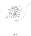
- Fig. 6 shows a new hearing aid 10 in its operating position with the BTE housing 12 behind the ear, i.e. behind the pinna 100, of the user.
- the illustrated new hearing aid 10 is similar to the hearing aids shown in Figs. 4 and 5 except for the fact that the ITE microphone 26 is positioned in the outer ear of the user outside the ear canal at the free end of an arm 30.
- the arm 30 is flexible and intended to be positioned inside the pinna 100, e.g. around the circumference of the conchae 102 behind the tragus 104 and antitragus 106 and abutting the antihelix 108 and at least partly covered by the antihelix for retaining its position inside the outer ear of the user.
- the arm may be pre-formed during manufacture, preferably into an arched shape with a curvature slightly larger than the curvature of the antihelix 104, for easy fitting of the arm 30 into its intended position in the pinna.
- the arm 30 contains electrical wires (not visible) for interconnection of the ITE microphone 26 with other parts of the BTE hearing aid circuitry.
- the arm 30 has a length and a shape that facilitate positioning of the ITE microphone 26 in an operating position below the triangular fossa.
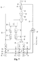
- Fig. 7 is a block diagram illustrating one exemplary signal processing in the new hearing aid 10.
- the illustrated hearing aid 10 has a front microphone 14 and a rear microphone 16 accommodated in the BTE hearing aid housing 12 configured to be worn behind the pinna of the user and for conversion of sound signals arriving at the microphones 14, 16 into respective audio sound signals 33, 35.
- the illustrated hearing aid 10 has an ITE microphone 26 accommodated in an earpiece (not shown) to be positioned in the outer ear of the user, for conversion of sound signals arriving at the microphone 26 into ITE audio sound signal 31.
- the microphone audio sound signals 31, 33, 35 are digitized and pre-processed, such as pre-filtered, in respective pre-processors 32, 34, 36.
- the pre-processed audio sound signals 38, 40 of the front and rear microphones 14, 16 are combined with, e.g. added to, each other in BTE signal combiner 50, and the combined signal 56, i.e. the BTE audio sound signal 56, is input to multiplier 46 for multiplication with gain values that are determined so that the signal magnitudes of the gain modified BTE audio sound signal 48 is identical to, or substantially identical to, the signal magnitudes of the ITE audio sound signal 60, whereby spatial cues in the ITE audio sound signal 60 are preserved.
- the signal detector 42 performs a spectral analysis of the ITE audio sound signal 60, and the signal magnitude detector 64 determines signal magnitudes of the ITE audio sound signal 60 at a plurality of frequencies.
- the signal detector 44 performs a spectral analysis of the BTE audio sound signal 56, and the signal magnitude detector 66 determines signal magnitudes of the BTE audio sound signal 56 at the plurality of frequencies.
- the gain processor 58 calculates gain values at respective frequencies of the plurality of frequencies based on the determined ITE audio sound signal magnitudes and BTE audio sound signal magnitudes, and outputs the determined gain values to the multiplier 46 that is connected for multiplying the BTE audio sound signal 56 with the determined gain values at the respective frequencies.
- the ITE microphone 26 is positioned in a location relative to the user of the hearing aid 10, wherein spatial cues of sound arriving at the location are preserved, e.g. at the entrance to the ear canal, inside the ear canal, immediately below the triangular fossa, etc.
- the BTE audio sound signal 56 is processed so that differences in signal magnitudes between the BTE audio sound signal 56 and the ITE audio sound signal 60 are reduced.
- the processing may be performed in a selected frequency range, or in a plurality of selected frequency ranges, or in the entire frequency range in which the hearing aid circuitry is capable of operating.
- the determined gain values at the plurality of frequencies may be converted to corresponding filter coefficients of a linear phase filter inserted into the signal path of the BTE audio sound signal 56; or, the gain values may be applied directly to the BTE audio sound signal 56 in the frequency domain.
- the determined gain values may further be compared to the corresponding maximum stable gain at the respective frequencies and for gain values that are larger than the respective maximum stable gains, the gain values may be substituted with the respective maximum stable gains, possibly minus a margin, to avoid risk of feedback.
- the gain modified BTE audio sound signal 48 may be input to the processor 18 for hearing loss compensation so that the ITE audio sound signal 60 does not form a direct part of the input to the processor 18, whereby risk of feedback is minimized.
- the hearing aid 10 further comprises a signal combiner 62 configured for combination of the ITE audio sound signal 60 with the gain modified BTE audio sound signal 48 and providing a combined output signal 52 connected to an input of the processor 18 for hearing loss compensation.
- the signal combiner 62 may output a weighted sum of the ITE and BTE audio sound signals 60, 48.
- the signal combiner may process the ITE audio sound signal 60 and BTE audio sound signal 56 differently in different frequency bands. For example, in selected frequency bands with no risk of feedback, the signal combiner 62 may pass the ITE audio sound signal 60 to the input of the processor 18, i.e. the ITE audio sound signal 60 may constitute the input signal 52, or the main part of the input signal 52, supplied to the input of the processor 18 and may cooperate with the processor 18 of the hearing aid 10 in a well-known way for hearing loss compensation. In this way, the ITE microphone 26 may be used as the sole input source to the processor 18 in a frequency band wherein the required gain for hearing loss compensation can be applied to the output signal 60 of the ITE microphone 26 without feedback.
- the signal combiner 62 may pass the gain modified BTE audio sound signal 48 to the input of the processor 18, i.e. the BTE audio sound signal 48 may constitute the input signal, or the main part of the input signal, supplied to the input of the processor 18 for provision of the required gain with minimum risk of feedback and preservation of spatial cues, at least to some extent, due to the multiplication of the BTE audio sound signal 56 in the multiplier 62.
- the signal combiner 62 may supply a weighted sum of the BTE audio sound signal 48 and the ITE audio sound signal 60 to the processor 18, the weighted sum forming a compromise between preservation of spatial cues and suppression of possible feedback.
- the combination of the signals 48, 60 could e.g. be based on different types of band pass filtering.
- the output signal 52 of the signal combiner 62 is input to processor 18 for hearing loss compensation, e.g. in a compressor.
- the hearing loss compensated signal 54 is output to the receiver 22 that converts the signal 54 to an acoustic output signal for transmission towards the ear drum of the user.
- the ITE microphone 26 operates as monitor microphone for generation of an audio sound signal 60 with the desired spatial information of the current sound environment due to its positioning in the outer ear of the user.
- the new hearing aid circuitry shown in Fig. 7 may operate in the entire frequency range of the hearing aid 10.
- the illustrated new hearing aid 10 also has adaptive feedback suppression circuitry, including an adaptive feedback filter 70 with an input 72 connected to the output of the hearing aid processor 18 and with individual outputs 74, 76-1, 76-2, each of which is connected to a respective subtractor 78, 80-1, 80-2 for subtraction of each output 74, 76-1, 76-2 from a respective microphone output 31, 33, 35 to provide a respective feedback compensated signal 82, 84-1, 84-2 as is well-known in the art.
- Each feedback compensated signal 82, 84-1, 84-2 is fed to the corresponding pre-processor 32, 34, 36, and also to the adaptive feedback filter 70 for control of the adaption of the adaptive feedback filter 70.
- the adaptive feedback filter outputs 74, 76-1, 76-2 provide signals that constitute approximations of corresponding feedback signals travelling from the output transducer 22 to the respective microphone 14, 16, 26 as is well-known in the art.
- the hearing aid 10 shown in Fig. 7 may be a multi-channel hearing aid in which microphone audio sound signals 31, 33, 35 to be processed are divided into a plurality of frequency channels, and wherein signals are processed individually in each of the frequency channels, possibly apart from the adaptive feedback suppression circuitry 70, 72, 74, 76-1, 76-2, 78, 80-1, 80-2, 82, 84-1, 84-2, 86 that may still operate in the entire frequency range; or, may be divided into other frequency channels, typically fewer frequency channels than the remaining illustrated circuitry.
- Fig. 7 may illustrate the circuitry and signal processing in a single frequency channel, as mentioned above possibly apart from the adaptive feedback suppression circuitry that may be divided into different frequency channels.
- the circuitry and signal processing may be duplicated in a plurality of the frequency channels, e.g. in all of the frequency channels.
- the signal processing illustrated in Fig. 7 may be performed in a selected frequency band, e.g. selected during fitting of the hearing aid to a specific user at a dispenser's office.
- the selected frequency band may comprise one or more of the frequency channels, or all of the frequency channels.
- the selected frequency band may be fragmented, i.e. the selected frequency band need not comprise consecutive frequency channels.
- the plurality of frequency channels may include warped frequency channels, for example all of the frequency channels may be warped frequency channels.
- the ITE microphone 26 may be connected conventionally as an input source to the processor 18 of the hearing aid 10 and may cooperate with the processor 18 of the hearing aid 10 in a well-known way.
- the ITE microphone 26 supplies the input to the hearing aid at frequencies where the hearing aid is capable of supplying the desired gain with this configuration.
- the microphones 14, 16 of BTE hearing aid housing are included in the signal processing as disclosed above. In this way, the gain can be increased while the spatial information of the sound environment as provided by the ITE microphone is simultaneously maintained.
- An arbitrary number N of ITE microphones may substitute the ITE microphone 26, and a combination of output signals from the N ITE microphones may be combined in a ITE signal combiner to form the ITE audio sound signal 60, e.g. as a weighted sum.
- the weights may be frequency dependent.
- an arbitrary number M of BTE microphones may substitute the BTE microphones 14, 16, and a combination of output signals from the M BTE microphones may be combined in a BTE signal combiner to form the BTE audio sound signal 56, e.g. as a weighted sum.
- the weights may be frequency dependent.
- Fig. 8 is a block diagram illustrating the same hearing aid 10 as in Fig. 7 and operating in the same way, except for the fact that a feedback monitor 86 has been added that is configured for monitoring the state of the adaptive feedback filter 70, e.g. in order to detect emerging feedback.
- the feedback monitor 86 provides a feedback monitor signal 88 accordingly.
- the gain processor 58 receives the monitor signal 88 and modifies its gain value calculation in response to the value of the monitor signal 88, i.e. in response to the state of feedback.
- the determined gain value may be lowered to reduce risk of feedback, e.g. in the entire frequency range in which the hearing aid circuitry is capable of operating, or, in a selected frequency band in which the feedback is otherwise expected to emerge.
- the lowered gain values may be changed gradually towards the gain values determined by the gain processor 58 without risk of feedback.
- ⁇ min ⁇ H ⁇ FB ⁇ H ⁇ FB ⁇ 2 2 ⁇ H ⁇ FB ⁇ 2 1
- ⁇ FB is the estimated feedback path response, e.g. from the output transducer 22 to the ITE audio sound signal 60 as modeled by adaptive feedback suppressor 70
- H FB is a stable feedback path response, e.g. determined during start-up of the hearing aid.
- the hearing aid 10 shown in Fig. 9 is similar to the hearing aid 10 shown in Fig. 8 and operates in the same way, apart from the fact that, in Fig. 9 , the signal combiner 62 is adaptive in response to the state of feedback as output by the feedback monitor 86.
- the ITE audio sound signal 60 of the at least one ITE microphone 26 may be used as the sole input source to the processor 18 in one or more frequency bands in which no feedback is currently present or emerging, whereas in one or more frequency bands in which feedback is present or evolving, the BTE audio sound signal 56 of the at least one BTE sound input transducer 14, 16 is applied to the signal processor 18 for provision of the required gain without feedback.
- the signal combiner 62 may adaptively connect the ITE audio sound signal 60 of the at least one ITE microphone 26 as the sole input source to the processor 18 in one or more frequency channels in which no feedback instability is currently detected by the feedback monitor 86, and the BTE audio sound signal 56 of the at least one BTE sound input transducer 14, 16 in frequency channels with current risk of feedback as detected by the feedback monitor 86.
Landscapes
- Health & Medical Sciences (AREA)
- General Health & Medical Sciences (AREA)
- Neurosurgery (AREA)
- Otolaryngology (AREA)
- Physics & Mathematics (AREA)
- Engineering & Computer Science (AREA)
- Acoustics & Sound (AREA)
- Signal Processing (AREA)
- Headphones And Earphones (AREA)
- Circuit For Audible Band Transducer (AREA)
Claims (10)
- BTE-Hörhilfe umfassend
ein BTE-Hörhilfengehäuse, das hinter der Ohrmuschel eines Benutzers zu tragen ist und mindestens einen BTE-Schalleingabewandler aufnimmt, der zur Wandlung von akustischem Schall in ein BTE-Audio-Schallsignal ausgebildet ist,
ein ITE-Mikrofongehäuse, das ausgebildet ist, um in dem äußeren Ohr des Benutzers positioniert zu werden, und mindestens ein ITE-Mikrofon, das zur Wandlung von akustischem Schall in ein ITE-Audio-Schallsignal ausgebildet ist, aufnimmt,
einen Signaldetektor, der ausgebildet ist, um
ITE-Signalstärken des ITE-Audio-Schallsignals mit mehreren Frequenzen zu bestimmen, und
BTE-Signalstärken des BTE-Audio-Schallsignals mit den mehreren Frequenzen zu bestimmen,
einen Verstärkungsprozessor zum Bestimmen von Verstärkungswerten bei jeweiligen Frequenzen der mehreren Frequenzen basierend auf den bestimmten ITE-Signalstärken und BTE-Signalstärken,
einen Multiplizierer, der ausgebildet ist, um das BTE-Audio-Schallsignal mit den Verstärkungswerten bei den jeweiligen Frequenzen zu multiplizieren, gekennzeichnet durch
einen Signalkombinierer, der ausgebildet ist, um eine gewichtete Summe des ITE-Audio-Schallsignals und des bezüglich der Verstärkung veränderten BTE-Audio-Schallsignals zu einem Prozessor auszugeben, der ausgebildet ist, um ein bezüglich des Hörverlusts kompensiertes Ausgangssignal zu erzeugen basierend auf der gewichteten Summe. - Hörhilfe nach Anspruch 1, umfassend
einen anpassungsfähigen Rückkopplungsunterdrücker zur Rückkopplungsunterdrückung, und der einen Eingang, der zum Empfang eines bezüglich des Hörverlusts kompensierten Ausgangssignals verbunden ist, mindestens einen Ausgang, von welchen jeder die Rückkopplungsstrecke von einem Ausgang der Hörhilfe zu einem des mindestens einen ITE-Mikrofons und mindestens einen BTE-Schalleingangswandlers modelliert und mit mindestens einem Subtrahierer zur Subtraktion der mindestens einen Ausgabe des anpassungsfähigen Rückkopplungsunterdrückers von der Ausgabe des einen des mindestens einen ITE-Mikrofons und des mindestens einen BTE-Schallwandlers und Ausgabe des jeweiligen Differenzsignals als jeweiliges des ITE-Audio-Schallsignals und BTE-Audio-Schallsignals verbunden ist, aufweist. - Hörhilfe nach Anspruch 2 umfassend
einen Rückkopplungsmonitor, der mit dem anpassungsfähigen Rückkopplungsunterdrücker verbunden ist und ausgebildet ist, um den Zustand der Rückkopplung zu überwachen, und der einen Ausgang aufweist, der eine Angabe bezüglich des Zustands der Rückkopplung bereitstellt, und wobei der Verstärkungsprozessor ferner einen Eingang aufweist, der mit dem Rückkopplungsmonitor verbunden ist, und wobei der Verstärkungsprozessor ausgebildet ist, um den Verstärkungswert an jeder der mehreren Frequenzen basierend auf den bestimmten ITE-Signalstärken und BTE-Signalstärken und einem Zustand der Rückkopplung zu bestimmen. - Hörhilfe nach Anspruch 3, wobei der Signalkombinierer ferner einen Eingang aufweist, der mit dem Rückkopplungsmonitor verbunden ist, und wobei der Signalkombinierer ausgebildet ist, um das ITE-Audio-Schallsignal mit dem BTE-Audio-Schallsignal in Reaktion auf den Zustand der Rückkopplung zu kombinieren.
- Hörhilfe nach einem der vorherigen Ansprüche, wobei der Verstärkungsprozessor ausgebildet ist, um den Verstärkungswert derart zu beschränken, dass die resultierende Verstärkung der Hörhilfe unter der maximalen stabilen Verstärkung bei den mehreren Frequenzen gehalten wird.
- Hörhilfe nach einem der vorherigen Ansprüche, wobei die ITE- und BTE-Audio-Schallsignale in mehrere Frequenzkanäle unterteilt sind, und wobei der Signaldetektor ausgebildet ist, um die Audio-Schallsignale individuell in ausgewählten Frequenzkanälen zu verarbeiten, von welchen jeder eine jeweilige der mehreren Frequenzen umfasst.
- Hörhilfe nach Anspruch 6, wobei der Signalkombinierer ausgebildet ist, um individuelle gewichtete Summen des ITE-Audio-Schallsignals und des bezüglich der Stärke veränderten BTE-Audio-Schallsignals in mindestens einigen der Frequenzkanäle zu bilden.
- Hörhilfe nach Anspruch 6 oder 7, wobei der mindestens eine BTE-Schalleingangswandler in einem ausgewählten Frequenzkanal der mehreren Frequenzkanäle derart getrennt ist, dass die Hörverlustkompensierung alleine auf dem ITE-Audio-Schallsignal in dem ausgewählten Frequenzkanal basiert.
- Verfahren zum Aufrechterhalten räumlicher Hinweise in einem Audio-Schallsignal, das in akustischen Schall zu wandeln ist, umfassend folgende Schritte:Wandeln von akustischem Schall in ein erstes Audio-Schallsignal,Anbringen mindestens eines Mikrofons an einem Ohr eines Benutzers zur Wandlung von akustischem Schall in ein zweites Audio-Schallsignal in einer Position an dem Ohr des Benutzers, in welcher räumliche Hinweise des akustischen Schalls in dem zweiten Audio-Schallsignal aufrechterhalten werden,Wandeln von akustischem Schall in das zweite Audio-Schallsignal unter Verwendung des mindestens einen Mikrofons,Bestimmen erster Signalstärken des ersten Audio-Schallsignals bei mehreren Frequenzen,Bestimmen zweiter Signalstärken des zweiten Audio-Schallsignals bei den mehreren Frequenzen,Bestimmen von Verstärkungswerten bei jeweiligen Frequenzen der mehreren Frequenzen basierend auf den bestimmten ersten Signalstärken und zweiten Signalstärken,Multiplizieren des ersten Audio-Schallsignals mit den bestimmten Verstärkungswerten bei den jeweiligen Frequenzen,gekennzeichnet durch folgende Schritte:Bilden einer gewichteten Summe des multiplizierten ersten Audio-Schallsignals und des zweiten Audio-Schallsignals, undDurchführen einer Hörverlustkompensierung basierend auf der gewichteten Summe.
- Verfahren nach Anspruch 9, umfassend folgende Schritte:Anbringen eines BTE-Hörhilfengehäuses, das mindestens einen BTE-Schalleingangswandler aufnimmt, in seiner Betriebsposition hinter der Ohrmuschel des Benutzers,Wandeln von akustischem Schall in das erste Audio-Schallsignal unter Verwendung des mindestens einen BTE-Schalleingangswandlers.
Priority Applications (5)
| Application Number | Priority Date | Filing Date | Title |
|---|---|---|---|
| EP13168718.8A EP2806660B1 (de) | 2013-05-22 | 2013-05-22 | Hörgerät mit verbesserter Ortung |
| DK13168718.8T DK2806660T3 (en) | 2013-05-22 | 2013-05-22 | A hearing aid with improved location |
| US13/901,386 US9100762B2 (en) | 2013-05-22 | 2013-05-23 | Hearing aid with improved localization |
| JP2014104599A JP5670593B2 (ja) | 2013-05-22 | 2014-05-20 | 定位が向上された補聴器 |
| CN201410219360.0A CN104185129B (zh) | 2013-05-22 | 2014-05-22 | 具有改善的定位的助听器 |
Applications Claiming Priority (1)
| Application Number | Priority Date | Filing Date | Title |
|---|---|---|---|
| EP13168718.8A EP2806660B1 (de) | 2013-05-22 | 2013-05-22 | Hörgerät mit verbesserter Ortung |
Publications (2)
| Publication Number | Publication Date |
|---|---|
| EP2806660A1 EP2806660A1 (de) | 2014-11-26 |
| EP2806660B1 true EP2806660B1 (de) | 2016-11-16 |
Family
ID=48446180
Family Applications (1)
| Application Number | Title | Priority Date | Filing Date |
|---|---|---|---|
| EP13168718.8A Active EP2806660B1 (de) | 2013-05-22 | 2013-05-22 | Hörgerät mit verbesserter Ortung |
Country Status (2)
| Country | Link |
|---|---|
| EP (1) | EP2806660B1 (de) |
| DK (1) | DK2806660T3 (de) |
Families Citing this family (4)
| Publication number | Priority date | Publication date | Assignee | Title |
|---|---|---|---|---|
| DK3503581T3 (da) * | 2017-12-21 | 2022-05-09 | Sonova Ag | Støjreduktion i et lydsignal til en høreenhed |
| EP3799444B1 (de) * | 2019-09-25 | 2025-04-09 | Oticon A/s | Hörgerät, ein richtmikrofonsystem umfassend |
| DK181045B1 (en) * | 2020-08-14 | 2022-10-18 | Gn Hearing As | Hearing device with in-ear microphone and related method |
| DK181039B1 (en) * | 2020-08-14 | 2022-10-11 | Gn Hearing As | Hearing device with microphone switching and related method |
Family Cites Families (4)
| Publication number | Priority date | Publication date | Assignee | Title |
|---|---|---|---|---|
| CA2647462C (en) * | 2006-04-01 | 2014-05-20 | Widex A/S | Hearing aid, and a method for control of adaptation rate in anti-feedback systems for hearing aids |
| EP2088802B1 (de) * | 2008-02-07 | 2013-07-10 | Oticon A/S | Verfahren zur Schätzung der Gewichtungsfunktion von Audiosignalen in einem Hörgerät |
| US8107654B2 (en) * | 2008-05-21 | 2012-01-31 | Starkey Laboratories, Inc | Mixing of in-the-ear microphone and outside-the-ear microphone signals to enhance spatial perception |
| JP4355359B1 (ja) * | 2008-05-27 | 2009-10-28 | パナソニック株式会社 | マイクを外耳道開口部に設置する耳掛型補聴器 |
-
2013
- 2013-05-22 EP EP13168718.8A patent/EP2806660B1/de active Active
- 2013-05-22 DK DK13168718.8T patent/DK2806660T3/en active
Non-Patent Citations (1)
| Title |
|---|
| None * |
Also Published As
| Publication number | Publication date |
|---|---|
| EP2806660A1 (de) | 2014-11-26 |
| DK2806660T3 (en) | 2017-02-06 |
Similar Documents
| Publication | Publication Date | Title |
|---|---|---|
| US9100762B2 (en) | Hearing aid with improved localization | |
| US9338561B2 (en) | Hearing aid with improved localization | |
| DK2611218T3 (en) | A hearing aid with improved location determination | |
| US9148735B2 (en) | Hearing aid with improved localization | |
| EP2611218B1 (de) | Hörgerät mit verbesserter Ortung | |
| US9432778B2 (en) | Hearing aid with improved localization of a monaural signal source | |
| US9148733B2 (en) | Hearing aid with improved localization | |
| JP2014140159A5 (de) | ||
| EP2806660B1 (de) | Hörgerät mit verbesserter Ortung | |
| EP2928213B1 (de) | Hörgerät mit verbesserter Lokalisierung einer monauralen Signalquelle | |
| EP2750410B1 (de) | Hörgerät mit verbesserter Lokalisation | |
| EP2750411B1 (de) | Hörgerät mit verbesserter Lokalisation | |
| EP2750412B1 (de) | Verbesserte Lokalisierung mit Feedback | |
| CN104980869A (zh) | 改进的单声道信号源定位的助听器 |
Legal Events
| Date | Code | Title | Description |
|---|---|---|---|
| PUAI | Public reference made under article 153(3) epc to a published international application that has entered the european phase |
Free format text: ORIGINAL CODE: 0009012 |
|
| 17P | Request for examination filed |
Effective date: 20130522 |
|
| AK | Designated contracting states |
Kind code of ref document: A1 Designated state(s): AL AT BE BG CH CY CZ DE DK EE ES FI FR GB GR HR HU IE IS IT LI LT LU LV MC MK MT NL NO PL PT RO RS SE SI SK SM TR |
|
| AX | Request for extension of the european patent |
Extension state: BA ME |
|
| R17P | Request for examination filed (corrected) |
Effective date: 20150511 |
|
| RBV | Designated contracting states (corrected) |
Designated state(s): AL AT BE BG CH CY CZ DE DK EE ES FI FR GB GR HR HU IE IS IT LI LT LU LV MC MK MT NL NO PL PT RO RS SE SI SK SM TR |
|
| 17Q | First examination report despatched |
Effective date: 20151028 |
|
| GRAP | Despatch of communication of intention to grant a patent |
Free format text: ORIGINAL CODE: EPIDOSNIGR1 |
|
| RIC1 | Information provided on ipc code assigned before grant |
Ipc: H04R 25/02 20060101ALN20160315BHEP Ipc: H04R 25/00 20060101AFI20160315BHEP |
|
| INTG | Intention to grant announced |
Effective date: 20160414 |
|
| GRAS | Grant fee paid |
Free format text: ORIGINAL CODE: EPIDOSNIGR3 |
|
| GRAJ | Information related to disapproval of communication of intention to grant by the applicant or resumption of examination proceedings by the epo deleted |
Free format text: ORIGINAL CODE: EPIDOSDIGR1 |
|
| GRAL | Information related to payment of fee for publishing/printing deleted |
Free format text: ORIGINAL CODE: EPIDOSDIGR3 |
|
| INTC | Intention to grant announced (deleted) | ||
| RIC1 | Information provided on ipc code assigned before grant |
Ipc: H04R 25/00 20060101AFI20160901BHEP Ipc: H04R 25/02 20060101ALN20160901BHEP |
|
| RIN1 | Information on inventor provided before grant (corrected) |
Inventor name: GRAN, KARL-FREDRIK JOHAN |
|
| GRAR | Information related to intention to grant a patent recorded |
Free format text: ORIGINAL CODE: EPIDOSNIGR71 |
|
| GRAA | (expected) grant |
Free format text: ORIGINAL CODE: 0009210 |
|
| AK | Designated contracting states |
Kind code of ref document: B1 Designated state(s): AL AT BE BG CH CY CZ DE DK EE ES FI FR GB GR HR HU IE IS IT LI LT LU LV MC MK MT NL NO PL PT RO RS SE SI SK SM TR |
|
| INTG | Intention to grant announced |
Effective date: 20161012 |
|
| REG | Reference to a national code |
Ref country code: GB Ref legal event code: FG4D |
|
| REG | Reference to a national code |
Ref country code: CH Ref legal event code: EP |
|
| REG | Reference to a national code |
Ref country code: IE Ref legal event code: FG4D |
|
| REG | Reference to a national code |
Ref country code: AT Ref legal event code: REF Ref document number: 846899 Country of ref document: AT Kind code of ref document: T Effective date: 20161215 |
|
| REG | Reference to a national code |
Ref country code: DE Ref legal event code: R096 Ref document number: 602013014020 Country of ref document: DE |
|
| REG | Reference to a national code |
Ref country code: DK Ref legal event code: T3 Effective date: 20170201 |
|
| PG25 | Lapsed in a contracting state [announced via postgrant information from national office to epo] |
Ref country code: LV Free format text: LAPSE BECAUSE OF FAILURE TO SUBMIT A TRANSLATION OF THE DESCRIPTION OR TO PAY THE FEE WITHIN THE PRESCRIBED TIME-LIMIT Effective date: 20161116 |
|
| REG | Reference to a national code |
Ref country code: NL Ref legal event code: MP Effective date: 20161116 |
|
| REG | Reference to a national code |
Ref country code: LT Ref legal event code: MG4D |
|
| REG | Reference to a national code |
Ref country code: AT Ref legal event code: MK05 Ref document number: 846899 Country of ref document: AT Kind code of ref document: T Effective date: 20161116 |
|
| PG25 | Lapsed in a contracting state [announced via postgrant information from national office to epo] |
Ref country code: GR Free format text: LAPSE BECAUSE OF FAILURE TO SUBMIT A TRANSLATION OF THE DESCRIPTION OR TO PAY THE FEE WITHIN THE PRESCRIBED TIME-LIMIT Effective date: 20170217 Ref country code: SE Free format text: LAPSE BECAUSE OF FAILURE TO SUBMIT A TRANSLATION OF THE DESCRIPTION OR TO PAY THE FEE WITHIN THE PRESCRIBED TIME-LIMIT Effective date: 20161116 Ref country code: NL Free format text: LAPSE BECAUSE OF FAILURE TO SUBMIT A TRANSLATION OF THE DESCRIPTION OR TO PAY THE FEE WITHIN THE PRESCRIBED TIME-LIMIT Effective date: 20161116 Ref country code: NO Free format text: LAPSE BECAUSE OF FAILURE TO SUBMIT A TRANSLATION OF THE DESCRIPTION OR TO PAY THE FEE WITHIN THE PRESCRIBED TIME-LIMIT Effective date: 20170216 Ref country code: LT Free format text: LAPSE BECAUSE OF FAILURE TO SUBMIT A TRANSLATION OF THE DESCRIPTION OR TO PAY THE FEE WITHIN THE PRESCRIBED TIME-LIMIT Effective date: 20161116 |
|
| REG | Reference to a national code |
Ref country code: FR Ref legal event code: PLFP Year of fee payment: 5 |
|
| PG25 | Lapsed in a contracting state [announced via postgrant information from national office to epo] |
Ref country code: HR Free format text: LAPSE BECAUSE OF FAILURE TO SUBMIT A TRANSLATION OF THE DESCRIPTION OR TO PAY THE FEE WITHIN THE PRESCRIBED TIME-LIMIT Effective date: 20161116 Ref country code: FI Free format text: LAPSE BECAUSE OF FAILURE TO SUBMIT A TRANSLATION OF THE DESCRIPTION OR TO PAY THE FEE WITHIN THE PRESCRIBED TIME-LIMIT Effective date: 20161116 Ref country code: PT Free format text: LAPSE BECAUSE OF FAILURE TO SUBMIT A TRANSLATION OF THE DESCRIPTION OR TO PAY THE FEE WITHIN THE PRESCRIBED TIME-LIMIT Effective date: 20170316 Ref country code: PL Free format text: LAPSE BECAUSE OF FAILURE TO SUBMIT A TRANSLATION OF THE DESCRIPTION OR TO PAY THE FEE WITHIN THE PRESCRIBED TIME-LIMIT Effective date: 20161116 Ref country code: AT Free format text: LAPSE BECAUSE OF FAILURE TO SUBMIT A TRANSLATION OF THE DESCRIPTION OR TO PAY THE FEE WITHIN THE PRESCRIBED TIME-LIMIT Effective date: 20161116 Ref country code: RS Free format text: LAPSE BECAUSE OF FAILURE TO SUBMIT A TRANSLATION OF THE DESCRIPTION OR TO PAY THE FEE WITHIN THE PRESCRIBED TIME-LIMIT Effective date: 20161116 Ref country code: ES Free format text: LAPSE BECAUSE OF FAILURE TO SUBMIT A TRANSLATION OF THE DESCRIPTION OR TO PAY THE FEE WITHIN THE PRESCRIBED TIME-LIMIT Effective date: 20161116 |
|
| PG25 | Lapsed in a contracting state [announced via postgrant information from national office to epo] |
Ref country code: CZ Free format text: LAPSE BECAUSE OF FAILURE TO SUBMIT A TRANSLATION OF THE DESCRIPTION OR TO PAY THE FEE WITHIN THE PRESCRIBED TIME-LIMIT Effective date: 20161116 Ref country code: SK Free format text: LAPSE BECAUSE OF FAILURE TO SUBMIT A TRANSLATION OF THE DESCRIPTION OR TO PAY THE FEE WITHIN THE PRESCRIBED TIME-LIMIT Effective date: 20161116 Ref country code: RO Free format text: LAPSE BECAUSE OF FAILURE TO SUBMIT A TRANSLATION OF THE DESCRIPTION OR TO PAY THE FEE WITHIN THE PRESCRIBED TIME-LIMIT Effective date: 20161116 Ref country code: EE Free format text: LAPSE BECAUSE OF FAILURE TO SUBMIT A TRANSLATION OF THE DESCRIPTION OR TO PAY THE FEE WITHIN THE PRESCRIBED TIME-LIMIT Effective date: 20161116 |
|
| REG | Reference to a national code |
Ref country code: DE Ref legal event code: R097 Ref document number: 602013014020 Country of ref document: DE |
|
| PG25 | Lapsed in a contracting state [announced via postgrant information from national office to epo] |
Ref country code: SM Free format text: LAPSE BECAUSE OF FAILURE TO SUBMIT A TRANSLATION OF THE DESCRIPTION OR TO PAY THE FEE WITHIN THE PRESCRIBED TIME-LIMIT Effective date: 20161116 Ref country code: LU Free format text: LAPSE BECAUSE OF NON-PAYMENT OF DUE FEES Effective date: 20170531 Ref country code: BE Free format text: LAPSE BECAUSE OF FAILURE TO SUBMIT A TRANSLATION OF THE DESCRIPTION OR TO PAY THE FEE WITHIN THE PRESCRIBED TIME-LIMIT Effective date: 20161116 Ref country code: BG Free format text: LAPSE BECAUSE OF FAILURE TO SUBMIT A TRANSLATION OF THE DESCRIPTION OR TO PAY THE FEE WITHIN THE PRESCRIBED TIME-LIMIT Effective date: 20170216 Ref country code: IT Free format text: LAPSE BECAUSE OF FAILURE TO SUBMIT A TRANSLATION OF THE DESCRIPTION OR TO PAY THE FEE WITHIN THE PRESCRIBED TIME-LIMIT Effective date: 20161116 |
|
| PLBE | No opposition filed within time limit |
Free format text: ORIGINAL CODE: 0009261 |
|
| STAA | Information on the status of an ep patent application or granted ep patent |
Free format text: STATUS: NO OPPOSITION FILED WITHIN TIME LIMIT |
|
| 26N | No opposition filed |
Effective date: 20170817 |
|
| PG25 | Lapsed in a contracting state [announced via postgrant information from national office to epo] |
Ref country code: SI Free format text: LAPSE BECAUSE OF FAILURE TO SUBMIT A TRANSLATION OF THE DESCRIPTION OR TO PAY THE FEE WITHIN THE PRESCRIBED TIME-LIMIT Effective date: 20161116 |
|
| PG25 | Lapsed in a contracting state [announced via postgrant information from national office to epo] |
Ref country code: MC Free format text: LAPSE BECAUSE OF FAILURE TO SUBMIT A TRANSLATION OF THE DESCRIPTION OR TO PAY THE FEE WITHIN THE PRESCRIBED TIME-LIMIT Effective date: 20161116 |
|
| REG | Reference to a national code |
Ref country code: IE Ref legal event code: MM4A |
|
| PG25 | Lapsed in a contracting state [announced via postgrant information from national office to epo] |
Ref country code: LU Free format text: LAPSE BECAUSE OF NON-PAYMENT OF DUE FEES Effective date: 20170522 |
|
| PG25 | Lapsed in a contracting state [announced via postgrant information from national office to epo] |
Ref country code: IE Free format text: LAPSE BECAUSE OF NON-PAYMENT OF DUE FEES Effective date: 20170522 |
|
| REG | Reference to a national code |
Ref country code: FR Ref legal event code: PLFP Year of fee payment: 6 |
|
| PG25 | Lapsed in a contracting state [announced via postgrant information from national office to epo] |
Ref country code: MT Free format text: LAPSE BECAUSE OF NON-PAYMENT OF DUE FEES Effective date: 20170522 |
|
| PG25 | Lapsed in a contracting state [announced via postgrant information from national office to epo] |
Ref country code: HU Free format text: LAPSE BECAUSE OF FAILURE TO SUBMIT A TRANSLATION OF THE DESCRIPTION OR TO PAY THE FEE WITHIN THE PRESCRIBED TIME-LIMIT; INVALID AB INITIO Effective date: 20130522 |
|
| PG25 | Lapsed in a contracting state [announced via postgrant information from national office to epo] |
Ref country code: CY Free format text: LAPSE BECAUSE OF FAILURE TO SUBMIT A TRANSLATION OF THE DESCRIPTION OR TO PAY THE FEE WITHIN THE PRESCRIBED TIME-LIMIT Effective date: 20161116 |
|
| PG25 | Lapsed in a contracting state [announced via postgrant information from national office to epo] |
Ref country code: MK Free format text: LAPSE BECAUSE OF FAILURE TO SUBMIT A TRANSLATION OF THE DESCRIPTION OR TO PAY THE FEE WITHIN THE PRESCRIBED TIME-LIMIT Effective date: 20161116 |
|
| PG25 | Lapsed in a contracting state [announced via postgrant information from national office to epo] |
Ref country code: TR Free format text: LAPSE BECAUSE OF FAILURE TO SUBMIT A TRANSLATION OF THE DESCRIPTION OR TO PAY THE FEE WITHIN THE PRESCRIBED TIME-LIMIT Effective date: 20161116 |
|
| PG25 | Lapsed in a contracting state [announced via postgrant information from national office to epo] |
Ref country code: AL Free format text: LAPSE BECAUSE OF FAILURE TO SUBMIT A TRANSLATION OF THE DESCRIPTION OR TO PAY THE FEE WITHIN THE PRESCRIBED TIME-LIMIT Effective date: 20161116 Ref country code: IS Free format text: LAPSE BECAUSE OF FAILURE TO SUBMIT A TRANSLATION OF THE DESCRIPTION OR TO PAY THE FEE WITHIN THE PRESCRIBED TIME-LIMIT Effective date: 20170316 |
|
| PGFP | Annual fee paid to national office [announced via postgrant information from national office to epo] |
Ref country code: GB Payment date: 20240517 Year of fee payment: 12 |
|
| PGFP | Annual fee paid to national office [announced via postgrant information from national office to epo] |
Ref country code: DK Payment date: 20240515 Year of fee payment: 12 |
|
| PGFP | Annual fee paid to national office [announced via postgrant information from national office to epo] |
Ref country code: DE Payment date: 20250520 Year of fee payment: 13 |
|
| PGFP | Annual fee paid to national office [announced via postgrant information from national office to epo] |
Ref country code: FR Payment date: 20250516 Year of fee payment: 13 |
|
| PGFP | Annual fee paid to national office [announced via postgrant information from national office to epo] |
Ref country code: CH Payment date: 20250601 Year of fee payment: 13 |
|
| REG | Reference to a national code |
Ref country code: DK Ref legal event code: EBP Effective date: 20250531 |
|
| GBPC | Gb: european patent ceased through non-payment of renewal fee |
Effective date: 20250522 |
|
| PG25 | Lapsed in a contracting state [announced via postgrant information from national office to epo] |
Ref country code: GB Free format text: LAPSE BECAUSE OF NON-PAYMENT OF DUE FEES Effective date: 20250522 |
|
| PG25 | Lapsed in a contracting state [announced via postgrant information from national office to epo] |
Ref country code: DK Free format text: LAPSE BECAUSE OF NON-PAYMENT OF DUE FEES Effective date: 20250531 |