EP2806708B1 - Heizkörper - Google Patents
Heizkörper Download PDFInfo
- Publication number
- EP2806708B1 EP2806708B1 EP14169169.1A EP14169169A EP2806708B1 EP 2806708 B1 EP2806708 B1 EP 2806708B1 EP 14169169 A EP14169169 A EP 14169169A EP 2806708 B1 EP2806708 B1 EP 2806708B1
- Authority
- EP
- European Patent Office
- Prior art keywords
- housing
- arrangement
- heater
- heating
- heating element
- Prior art date
- Legal status (The legal status is an assumption and is not a legal conclusion. Google has not performed a legal analysis and makes no representation as to the accuracy of the status listed.)
- Active
Links
Images

Classifications
-
- H—ELECTRICITY
- H05—ELECTRIC TECHNIQUES NOT OTHERWISE PROVIDED FOR
- H05B—ELECTRIC HEATING; ELECTRIC LIGHT SOURCES NOT OTHERWISE PROVIDED FOR; CIRCUIT ARRANGEMENTS FOR ELECTRIC LIGHT SOURCES, IN GENERAL
- H05B3/00—Ohmic-resistance heating
- H05B3/02—Details
- H05B3/06—Heater elements structurally combined with coupling elements or holders
-
- F—MECHANICAL ENGINEERING; LIGHTING; HEATING; WEAPONS; BLASTING
- F24—HEATING; RANGES; VENTILATING
- F24H—FLUID HEATERS, e.g. WATER OR AIR HEATERS, HAVING HEAT-GENERATING MEANS, e.g. HEAT PUMPS, IN GENERAL
- F24H3/00—Air heaters
- F24H3/02—Air heaters with forced circulation
- F24H3/04—Air heaters with forced circulation the air being in direct contact with the heating medium, e.g. electric heating element
- F24H3/0405—Air heaters with forced circulation the air being in direct contact with the heating medium, e.g. electric heating element using electric energy supply, e.g. the heating medium being a resistive element; Heating by direct contact, i.e. with resistive elements, electrodes and fins being bonded together without additional element in-between
- F24H3/0429—For vehicles
-
- F—MECHANICAL ENGINEERING; LIGHTING; HEATING; WEAPONS; BLASTING
- F24—HEATING; RANGES; VENTILATING
- F24H—FLUID HEATERS, e.g. WATER OR AIR HEATERS, HAVING HEAT-GENERATING MEANS, e.g. HEAT PUMPS, IN GENERAL
- F24H9/00—Details
- F24H9/18—Arrangement or mounting of grates or heating means
- F24H9/1854—Arrangement or mounting of grates or heating means for air heaters
- F24H9/1863—Arrangement or mounting of electric heating means
- F24H9/1872—PTC resistor
-
- H—ELECTRICITY
- H05—ELECTRIC TECHNIQUES NOT OTHERWISE PROVIDED FOR
- H05B—ELECTRIC HEATING; ELECTRIC LIGHT SOURCES NOT OTHERWISE PROVIDED FOR; CIRCUIT ARRANGEMENTS FOR ELECTRIC LIGHT SOURCES, IN GENERAL
- H05B2203/00—Aspects relating to Ohmic resistive heating covered by group H05B3/00
- H05B2203/022—Heaters specially adapted for heating gaseous material
- H05B2203/023—Heaters of the type used for electrically heating the air blown in a vehicle compartment by the vehicle heating system
Definitions
- the invention relates to an arrangement of a heating element and a housing, in particular for a heating or air conditioning system in a motor vehicle, with at least one heating element which is used to heat a fluid flow, the heating element being electrically conductively connected to a voltage source and having live areas.
- Electrically operated heating elements can be used for additional heating of fluid streams.
- a plurality of heating elements is regularly combined to form a radiator.
- the heating element can heat up either completely through the electrically operated heating elements or coupled with structures through which liquid flows, such as a tube-fin block of a heat exchanger.
- Resistance heating elements which convert electrical energy into heat, can be used for heating. So-called PTC heating elements (Positive Temperature Coefficient) are particularly preferred. The use of other electrically operated heating elements can also be provided as an alternative.
- grounding is provided in electrical heating elements.
- a defect in the grounding can lead to a failure of the entire heating element and at the same time increase the risk of a voltage accident.
- the EP 2 161 514 A1 discloses a heater with a plurality of electrically operated heating elements, which are used to heat a fluid flow, the respective heating element being electrically conductively connectable to a voltage source and having live areas, a housing being provided which covers the live areas of the heating elements, the The housing has an opening at one of its end regions, through which the heating element protrudes into the housing, the housing being made in several parts and being divisible for inserting the heating element.
- the EP 2 466 222 A1 also discloses a heater with a plurality of electrically operated heating elements, which are used to heat a fluid flow, the respective heating element being electrically conductively connectable to a voltage source and having live areas, a housing being provided which covers the live areas of the heating elements, wherein the housing is designed in several parts and can be divided to insert the heating elements.
- An exemplary embodiment of the invention relates to an arrangement of a heating element and a housing, in particular for a heating or air conditioning system in a motor vehicle, with a plurality of electrical heating elements which are used to heat a fluid flow, with the respective heating element being electrically conductively connected to a voltage source, and has live areas, with an electrically insulating layer being provided, which is designed as a housing and at least partially covers the live areas of the heating element.
- a heating element can either be heated purely by electrically operated heating elements or in combination with a structure through which fluid flows, such as a tube-fin block of a heat exchanger.
- Electrically powered heating elements often have large areas which are in contact with a voltage source and thus pose a potential hazard to humans from electric shock.
- a housing as an electrically insulating layer means here an element which is in electrically conductive contact with a voltage source Surfaces of the heating element are covered as completely as possible. In this case, the possibility is preferably retained that a fluid to be heated enters into thermal exchange with the heating elements.
- the housing either has suitable recesses or, in addition to the electrically insulating property, also has a thermally conductive property. In order to keep the efficiency of the heating element as high as possible, it is advantageous if the thermal conductivity of the housing is particularly high.
- the stability of the radiator can also be positively influenced via a housing.
- the heating element is formed by a PTC heating element.
- a PTC heating element is particularly advantageous because it can be produced inexpensively and it can be shaped to suit the application. Furthermore, PTC elements have a self-regulating property. This means that as the temperature rises, the resistance also increases, which reduces the heating capacity. A constant temperature level can thus be maintained.
- the heating element has a plurality of heating elements, which are arranged in several rows arranged adjacent to one another.
- the performance of the heater can be specifically influenced by using a plurality of heating elements.
- the heating elements can be connected in series and/or parallel to one another.
- a heating output that is tailored to the specific requirements can thus be generated via appropriate interconnections and/or a control unit.
- the heating elements are designed for a supply voltage of more than 110 volts.
- the voltage of the vehicle electrical system is significantly higher than the 12 volts or 24 volts that are common in conventional vehicles today.
- the heating elements are therefore advantageously designed for supply voltages of more than 110 volts.
- the housing has an opening at one of its end regions, through which the heating element can be inserted into the housing.
- heating element can be inserted into the housing in a simple manner. This facilitates assembly and production in particular.
- the housing is designed in several parts and can be divided to insert the heating element.
- a multi-part design can be particularly advantageous if the heating element is to be inserted completely into the housing. Depending on the version, part of the heating element can protrude beyond the housing. For this purpose, openings are advantageously provided in the housing. It can be particularly advantageous if the heating element has a control unit on one of its end regions, and this control unit protrudes beyond the housing or protrudes from the housing. This makes it easier to contact the control unit.
- the housing can advantageously be divided into a housing upper part and a housing lower part.
- the heating element can be inserted into the lower part of the housing by lifting off the upper part of the housing.
- the housing is formed by a rectangular picture frame-like boundary and a lattice-like structure which runs between the boundary, the lattice-like structure being formed by a plurality of struts running at right angles to one another.
- the rectangular, picture-frame-like boundary is essentially formed by four profile pieces, which are arranged relative to one another in such a way that they form a rectangle.
- the profile pieces can have almost any desired cross section.
- the profile pieces have a rectangular cross section and are formed as flat, flat strips of material.
- Horizontal and vertical struts run between the boundary described.
- a first number of struts covers the live parts of the heater, thereby preventing contact with the live parts.
- a second number of struts serves to stabilize the lattice-like structure.
- the grid-like structure forms the areas spanned by the picture-frame-like boundary. In this case, these surfaces can form the entry surface and the exit surface for a fluid which flows through the heating element.
- the lattice-like structure forms a surface that is perpendicular to the direction of flow of the fluid.
- the lattice-like structure of the housing is designed in such a delicate manner that reaching through the housing with a human hand and/or human fingers is effectively prevented.
- the grid-like structure is designed so delicately that human hands and in particular human fingers cannot reach through the structure. This is to prevent contact with the live parts of the heating elements. Especially in light of the rapidly increasing vehicle electrical system voltage effective protection of people against live parts is necessary.
- the grid-like structure the mesh size of which can be adjusted depending on the area of application, also makes it possible to achieve different protection classes, such as those defined in the standards (see IEC 60947-1), with simple means. To achieve a higher protection class, for example, the mesh size can be reduced.
- the housing is advantageously designed in such a way that, despite the effective prevention of contact with the live parts, a thermal exchange between a fluid to be heated and the heating elements remains possible.
- Recesses in the housing for example, can contribute to this.
- the housing is at least partially made of an electrically non-conductive material.
- the surfaces of the housing that face outwards and with which a person can come into contact should be made of an electrically non-conductive material.
- other areas of the housing, such as inner surfaces, can very well be electrically conductive.
- the housing has connecting elements, via which the heating element can be positioned and/or fixed relative to surrounding structures.
- the heating element can be advantageously positioned in relation to other structures, for example in a motor vehicle, by means of connecting elements on the housing.
- the connecting elements can also enable the housing to be fixed to a structure surrounding the housing.
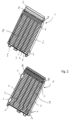
- the 1 shows a perspective view of a housing upper part 1.
- the housing upper part 1 is essentially formed by two parallel opposing edge elements 2, which are connected to one another via a housing element 9 and a housing element 6, respectively.
- the housing element 9 is arranged in the lower area and the housing element 6 is arranged in the upper area of the upper housing part 1 .
- the edge elements 2 and the housing elements 6 and 9 form a boundary between which both vertical struts 3 and horizontal struts 4 are arranged.
- the entire upper housing part 1 is made of an electrically non-conductive material, such as a plastic.
- the housing upper part is advantageously produced by a method that is common for plastics processing, such as an injection molding method.
- the edge elements 2 each have a recess 7 at their respective end regions. These recesses 7 are directed outwards and serve in particular to accommodate snap hooks of the lower housing part. Through a positive connection of the in 2 Snap hooks shown and the recesses 7, the upper housing part 1 and the lower housing part 10 can be connected to form a housing.
- Connecting elements 5 are arranged on the lower housing element 9 . In the embodiment shown, there are three. However, the number can also be varied.
- the connecting elements 5 serve to position and fix the housing to structures which surround the housing in an installation situation.
- the connecting elements 5 correspond to the in 2 shown connecting elements 15.
- Indentations 8 are arranged on the lateral end regions of the upper housing element 6 . These are designed as cylindrical indentations. They are used to position the lower part of the housing relative to the upper part of the housing 1.
- the vertical struts 3 and the horizontal struts 4 are arranged in such a way that a lattice-like structure 18 is formed.
- This grid-like structure 18 has a plurality of meshes. The size of the mesh is based on the positioning of the vertical and horizontal struts 3 and 4 to each other.
- the vertical struts 3 and/or the horizontal struts 4 are positioned in such a way that they cover a heater and in particular the live parts of a heater that can be inserted into the housing in such a way that no contact with the live parts is possible from the outside .
- the size of the individual meshes formed by the lattice-like structure 18 is designed in such a way that reaching through with a human hand or human fingers is avoided. In this way, effective protection against voltage accidents can be created.
- the heating element used in the housing shown advantageously consists of a plurality of electrically operable heating elements.
- a voltage of several 100 volts can be applied to these heating elements, particularly when used in electric vehicles. Voltages of this magnitude are dangerous for people, especially with brief contact, and can lead to serious injuries. It is therefore essential to avoid touching these live areas.
- the lattice-like structure 18 is arranged in particular on the areas of the edge elements 2 or the housing elements 6 and 9 that are away from the viewer in the viewing direction. This results in particular when connecting the upper housing part 1 to the in 2 Lower housing part 10 shown is a cavity inside the housing. The radiator can consequently be inserted into this cavity.
- the 2 shows a perspective view of the lower housing part 10. The view is also directed towards the inside of the lower housing part 10.
- the lower housing part 10 consists essentially of two opposing edge elements 12, which are connected to one another in the lower and in the upper area by housing elements. Like the upper housing part 1, the lower housing part 10 also has a lattice-like structure 19, which is formed from both vertical struts 13 and horizontal struts 14.
- the opposing edge elements 12 each have a snap hook 11 at their end regions. These snap hooks 11 are designed in such a way that they fit into the 1 Recesses 7 shown, which are arranged at corresponding points of the edge elements 2 of the housing upper part 1, can engage and thus the two housing parts can be firmly connected to each other.
- the distribution of the vertical struts 13 and the horizontal struts 14 differs from the area above it. This can result, for example, from a different arrangement of the heating elements of the radiator to be inserted.
- the in the Figures 1 and 2 shown representation of the grid-like structure 18, 19 by way of example. Arrangements of the vertical or horizontal struts 3, 4, 13, 14 that deviate from this can also be provided.
- the struts run along the live parts so that they are exactly covered by the struts. The arrangement of the struts is therefore based on the course of the live parts.
- the housing can also be designed in such a way that direct contact with the live parts is avoided by the grid-like structure, without the struts being oriented towards the arrangement of the live parts.
- Connecting elements 15 are arranged on the lower area of the lower housing part 10 . These are used to position the housing that will be assembled later of the housing in relation to a structure surrounding the housing, as can arise, for example, in motor vehicles.
- Projections 16 are arranged on the lateral edge elements 12 in the upper area of the lattice-like structure 19 . These projections 16 correspond in terms of their arrangement and their fit with the indentations 8 which are shown in the upper part 1 of the housing. They are used to position and fix the housing parts 1, 10 together.
- the 3 shows a perspective view of the fully assembled housing 20.
- the view is directed towards the housing upper part 1.
- the housing 20 has a boundary 22 which is formed by the edge elements 2 and 12, the housing elements 6 and 9 of the upper part of the housing and the housing elements of the lower part 10 of the housing.
- the snap hooks 11 engage in the recesses 7 and thus connect the housing upper part 1 to the housing lower part 10.
- the connecting means 5 and 15 of the housing parts 1 and 10, respectively are the connecting means 5 and 15 of the housing parts 1 and 10, respectively, so that they form a tapered block which can be used to position the housing 20.
- the blocks taper, which in particular facilitates insertion into openings. It is particularly advantageous if these connecting elements 5 or 15 are designed in such a way that they can be inserted into openings corresponding to them in a structure surrounding the housing 20 .
- a receiving portion 21 is provided at the upper end portion of the housing 20 . This is used, for example, to accommodate a control unit. Furthermore, the housing 20 has an opening on the upper receiving area 21 through which a heating element 26 can be pushed into the housing 20 .
- the housing 20 shown is thus a body which is closed on five sides and open on one side and which can accommodate a heating element 26 .
- the grid-like structures 18, 19 at the The front and back of the housing 20 prevent a voltage accident from occurring as a result of touching the live parts of the heating element inserted into the housing 20 .
- the 4 shows the housing 20 in a plan view of the lower housing part 10.
- the boundary 22 and the upper receiving area 21 are also shown 4 is in addition to 3 the lower area 17 of the lower housing part 10 can also be seen, which has a different arrangement of the grid-like structure 19 .
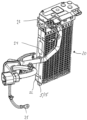
- the figure 5 shows a further perspective view of the housing 20 with the heating element inserted.
- a control unit 23 is connected to the receiving area 21 and is connected to an electric circuit via connection lines 24 .
- a grounding cable or connecting cable 25 leads out of a connector plug, via which the radiator 1 can be grounded, for example.
- the connecting elements 5 and 15 are arranged. As already described above, these can in particular be attached to counter-elements that correspond to them or pushed into them in order to position and fix the housing 20 as a whole.
Landscapes
- Engineering & Computer Science (AREA)
- Physics & Mathematics (AREA)
- Thermal Sciences (AREA)
- Chemical & Material Sciences (AREA)
- Combustion & Propulsion (AREA)
- Mechanical Engineering (AREA)
- General Engineering & Computer Science (AREA)
- Air-Conditioning For Vehicles (AREA)
Description
- Die Erfindung betrifft eine Anordnung eines Heizkörpers und eines Gehäuses, insbesondere für eine Heizungs- oder Klimaanlage in einem Kraftfahrzeug, mit zumindest einem Heizelement, welches zur Erwärmung eines Fluidstromes dient, wobei das Heizelement mit einer Spannungsquelle elektrisch leitend verbunden ist, und spannungsführende Bereiche aufweist.
- Zur zusätzlichen Beheizung von Fluidströmen können elektrisch betriebene Heizelemente verwendet werden. Eine Mehrzahl von Heizelementen ist regelmäßig zu einem Heizkörper zusammengefasst. Der Heizkörper kann die Aufheizung dabei entweder vollständig durch die elektrisch betriebenen Heizelemente erreichen oder gekoppelt mit flüssigkeitsdurchströmten Strukturen, wie beispielsweise einem Rohr-Rippen-Block eines Wärmeübertragers.
- Auf diese Weise kann beispielsweise ein zu geringer Wärmefluss von einer Verbrennungskraftmaschine ausgeglichen werden oder ein elektrisch angetriebenes Fahrzeug beheizt werden. In elektrisch angetriebenen Fahrzeugen werden zunehmend Hochspannungsstromkreise verwendet, die eine Spannung von mehreren hundert Volt aufweisen.
- Zur Beheizung können dabei Widerstandsheizelemente eingesetzt werden, die elektrische Energie in Wärme umwandeln. Besonders bevorzugt sind dabei sogenannte PTC-Heizelemente (Positive-Temperature-Coefficient). Auch der Einsatz von anderen elektrisch betriebenen Heizelementen kann alternativ vorgesehen werden.
- Um das Risiko für Spannungsunfälle und Fehlfunktionen zu senken, werden in elektrischen Heizelementen Erdungen vorgesehen. Ein Defekt der Erdung kann dabei jedoch zu einem Ausfall des gesamten Heizelementes führen und gleichzeitig das Risiko für einen Spannungsunfall erhöhen.
- Die
EP 2 161 514 A1 offenbart einen Heizkörper mit einer Mehrzahl von elektrisch betriebenen Heizelementen, welche zur Erwärmung eines Fluidstromes dienen, wobei das jeweilige Heizelement mit einer Spannungsquelle elektrisch leitend verbindbar ist und spannungsführende Bereiche aufweist, wobei ein Gehäuse vorgesehen ist, welches die spannungsführenden Bereiche der Heizelemente überdeckt, wobei das Gehäuse an einem seiner Endbereiche eine Öffnung aufweist, durch welche der Heizkörper in das Gehäuse hineinragt, wobei das Gehäuse mehrteilig ausgeführt ist und zum Einlegen des Heizkörpers teilbar ist. - Die
EP 2 466 222 A1 offenbart ebenso einen Heizkörper mit einer Mehrzahl von elektrisch betriebenen Heizelementen, welche zur Erwärmung eines Fluidstromes dienen, wobei das jeweilige Heizelement mit einer Spannungsquelle elektrisch leitend verbindbar ist und spannungsführende Bereiche aufweist, wobei ein Gehäuse vorgesehen ist, welches die spannungsführenden Bereiche der Heizelemente überdeckt, wobei das Gehäuse mehrteilig ausgeführt ist und zum Einlegen der Heizelemente teilbar ist. - Nachteilig an den Lösungen im Stand der Technik ist insbesondere, dass die verwendeten elektrischen Heizelemente keinen oder einen nur unzureichenden Schutz gegen elektrische Schocks von Personen aufweisen. Es besteht somit für Personen, die in Berührung mit den elektrischen Heizelementen kommen, die Gefahr einen elektrischen Schlag zu erleiden.
- Es ist die Aufgabe der vorliegenden Erfindung eine Anordnung eines Heizkörpers und eines Gehäuses bereitzustellen, die im Vergleich zu den Lösungen im Stand der Technik einen verbesserten Schutz gegen Spannungsunfälle, insbesondere mit Menschen, aufweist.
- Die Aufgabe wird durch eine Anordnung mit den Merkmalen des Anspruchs 1 gelöst.
- Ein Ausführungsbeispiel der Erfindung betrifft eine Anordnung eines Heizkörpers und eines Gehäuses, insbesondere für eine Heizungs- oder Klimaanlage in einem Kraftfahrzeug, mit einer Mehrzahl von elektrischen Heizelementen, welche zur Erwärmung eines Fluidstromes dienen, wobei das jeweilige Heizelement mit einer Spannungsquelle elektrisch leitend verbunden ist, und spannungsführende Bereiche aufweist, wobei eine elektrisch isolierende Schicht vorgesehen ist, welche als Gehäuse ausgebildet ist und die spannungsführenden Bereiche des Heizelementes zumindest teilweise überdeckt.
- Ein Heizkörper kann dabei entweder eine Erwärmung rein durch elektrisch betriebene Heizelemente erreichen oder in Kombination mit einer fluiddurchströmten Struktur, wie beispielsweise einem Rohr-Rippen-Block eines Wärmeübertragers.
- Elektrisch betriebene Heizelemente weisen oftmals große Flächen auf, welche mit einer Spannungsquelle in Verbindung stehen und damit für Menschen eine potentielle Gefahr hinsichtlich eines elektrischen Schlages bilden.
- Mit einem Gehäuse als elektrisch isolierende Schicht ist hier ein Element gemeint, welches die mit einer Spannungsquelle in elektrisch leitendem Kontakt stehenden Flächen des Heizelementes möglichst vollständig überdeckt. Dabei bleibt vorzugsweise die Möglichkeit erhalten, dass ein zu erwärmendes Fluid mit den Heizelementen in thermischen Austausch tritt. Das Gehäuse weist hierzu entweder geeignete Aussparungen auf oder besitzt neben der elektrisch isolierenden Eigenschaft auch eine thermisch leitende Eigenschaft. Um die Leistungsfähigkeit des Heizkörpers möglichst groß zu halten, ist es vorteilhaft, wenn die thermische Leitfähigkeit des Gehäuses besonders hoch ist.
- Über ein Gehäuse kann außerdem die Stabilität des Heizkörpers positiv beeinflusst werden.
- Darüber hinaus kann es vorteilhaft sein, wenn das Heizelement durch ein PTC-Heizelement gebildet ist.
- Ein PTC-Heizelement ist besonders vorteilhaft, da es kostengünstig herzustellen ist und eine an den Anwendungszweck angepasste Formgebung möglich ist. Weiterhin weisen PTC-Elemente eine selbstregulierende Eigenschaft auf. Dies bedeutet, dass bei steigender Temperatur auch der Widerstand wächst, wodurch die Heizleistung sinkt. Es kann somit ein konstantes Temperaturniveau gehalten werden.
- In einer alternativen Ausgestaltung der Erfindung kann es vorgesehen sein, dass der Heizkörper eine Mehrzahl von Heizelementen aufweist, welche in mehreren zueinander benachbart angeordneten Reihen angeordnet sind.
- Die Leistungsfähigkeit des Heizkörpers kann durch die Verwendung einer Mehrzahl von Heizelementen gezielt beeinflusst werden. Die Heizelemente können dabei in Reihe und/oder parallel zueinander geschaltet werden. Über entsprechende Verschaltungen und/oder ein Steuergerät lässt sich so jeweils eine auf die speziellen Anforderungen abgestimmte Heizleistung erzeugen.
- In einer besonders günstigen Ausgestaltung der Erfindung ist es außerdem vorgesehen, dass die Heizelemente für eine Versorgungsspannung von mehr als 110 Volt ausgelegt sind.
- Insbesondere in elektrisch angetriebenen Fahrzeugen liegt die Spannung des Bordnetzes deutlich höher als die heute in konventionellen Fahrzeugen üblichen 12 Volt oder 24 Volt. Die Heizelemente sind daher vorteilhafterweise für Versorgungsspannungen von mehr als 110 Volt ausgelegt.
- Erfindungsgemäß weist das Gehäuse an einem seiner Endbereiche eine Öffnung auf, durch welche der Heizkörper in das Gehäuse einführbar ist.
- Dies ist besonders vorteilhaft, da so der Heizkörper auf einfache Weise in das Gehäuse eingeführt werden kann. Dies erleichtert insbesondere die Montage und Fertigung.
- Erfindungsgemäß ist das Gehäuse mehrteilig ausgeführt und zum Einlegen des Heizkörpers teilbar.
- Eine mehrteilige Ausführung kann besonders vorteilhaft sein, wenn der Heizkörper vollständig in das Gehäuse eingelegt werden soll. Je nach Ausführung kann dennoch ein Teil des Heizkörpers über das Gehäuse hinausstehen. Hierzu sind vorteilhafterweise Öffnungen im Gehäuse vorgesehen. Besonders vorteilhaft kann es sein, wenn der Heizkörper eine Steuereinheit an einem seiner Endbereiche aufweist, und diese Steuereinheit über das Gehäuse übersteht oder aus dem Gehäuse hinaussteht. Eine Kontaktierung der Steuereinheit wird dadurch erleichtert.
- Das Gehäuse kann dabei vorteilhafterweise in ein Gehäuseoberteil und ein Gehäuseunterteil geteilt sein. Durch das Abheben des Gehäuseoberteils kann der Heizkörper in das Gehäuseunterteil eingelegt werden.
- Erfindungsgemäß ist das Gehäuse durch eine rechteckige bilderrahmenartige Begrenzung und eine gitterartige Struktur gebildet, die zwischen der Begrenzung verläuft, wobei die gitterartige Struktur durch mehrere rechtwinklig zueinander verlaufende Streben gebildet ist.
- Die rechteckige bilderrahmenartige Begrenzung ist im Wesentlichen durch vier Profilstücke gebildet, welche derart zueinander angeordnet sind, dass sie ein Rechteck bilden. Die Profilstücke können dabei einen annähernd beliebigen Querschnitt aufweisen. Vorteilhafterweise weisen die Profilstücke einen rechteckigen Querschnitt auf und sind als ebene flächige Materialstreifen gebildet.
- Zwischen der beschriebenen Begrenzung verlaufen horizontale und vertikale Streben. Eine erste Anzahl der Streben überdeckt dabei die spannungsführenden Teile des Heizkörpers, wodurch ein Kontakt mit den spannungsführenden Teilen unterbunden wird. Eine zweite Anzahl der Streben dient dabei der Stabilisierung der gitterartigen Struktur.
- Die gitterartige Struktur bildet dabei die von der bilderrahmenartige Begrenzung aufgespannten Flächen aus. Diese Flächen können dabei die Eintrittsfläche und die Austrittsfläche für ein Fluid bilden, welches den Heizkörper durchströmt. Die gitterartige Struktur bildet dabei eine Fläche, welche senkrecht zur Strömungsrichtung des Fluids steht.
- Weiterhin ist es vorteilhaft, wenn die gitterartige Struktur des Gehäuses derart feingliedrig ausgebildet ist, dass ein Durchgreifen des Gehäuses mit einer menschlichen Hand und/oder mit menschlichen Fingern wirksam verhindert ist.
- Die gitterartige Struktur ist dabei so feingliedrig ausgebildet, dass menschliche Hände und insbesondere menschliche Finger nicht durch die Struktur greifen können. Dadurch soll ein Kontakt mir den spannungsführenden Teilen der Heizelemente verhindert werden. Insbesondere im Lichte der stark ansteigenden Bordnetzspannung ist ein wirksamer Schutz des Menschen gegenüber spannungsführenden Teilen notwendig.
- Die gitterartige Struktur, deren Maschengröße je nach Einsatzgebiet angepasst werden kann, ermöglicht es auch unterschiedliche Schutzklassen, wie sie beispielsweise in den Normen (siehe IEC 60947-1) definiert sind, mit einfachen Mitteln zu erreichen. Zum Erreichen einer höheren Schutzklasse kann dabei beispielsweise die Maschengröße verringert werden.
- Vorteilhafterweise ist das Gehäuse derart gestaltet, dass trotz der wirksamen Verhinderung eines Kontaktes mit den spannungsführenden Teilen ein thermischer Austausch zwischen einem zu erwärmenden Fluid und den Heizelementen möglich bleibt. Hierzu können beispielsweise Aussparungen im Gehäuse beitragen.
- Weiterhin ist es vorteilhaft, wenn das Gehäuse zumindest teilweise aus einem elektrisch nicht leitenden Material gefertigt ist.
- Insbesondere die nach außen gewandten Flächen des Gehäuses, mit welchen ein Mensch in Kontakt geraten kann, sollten aus einem elektrisch nicht leitenden Material gefertigt sein. Andere Bereiche des Gehäuses, wie beispielsweise Innenflächen, können dagegen sehr wohl elektrisch leitfähig sein.
- Darüber hinaus ist es zweckmäßig, wenn das Gehäuse Verbindungselemente aufweist, über welche der Heizkörper relativ zu umliegenden Strukturen positionierbar und/oder fixierbar ist.
- Über Verbindungselemente am Gehäuse kann der Heizkörper vorteilhaft gegenüber anderen Strukturen, beispielsweise in einem Kraftfahrzeug, positioniert werden. Gleichzeitig können die Verbindungselemente auch eine Fixierung des Gehäuses an einer das Gehäuse umgebenden Struktur ermöglichen.
- Vorteilhafte Weiterbildungen der vorliegenden Erfindung sind in den Unteransprüchen und der nachfolgenden Figurenbeschreibung beschrieben.
- Im Folgenden wird die Erfindung anhand von Ausführungsbeispielen unter Bezugnahme auf die Zeichnungen detailliert erläutert. In den Zeichnungen zeigen:
- Fig.1
- eine perspektivische Ansicht des Gehäuseoberteils eines erfindungsgemäβen Gehäuses, wobei der Blick auf die Innenseite des Gehäuseoberteils gerichtet ist,
- Fig. 2
- eine perspektivische Ansicht des Gehäuseunterteils eines erfindungsgemäβen Gehäuses, wobei der Blick auf die Innenseite des Gehäuseunterteils gerichtet ist,
- Fig. 3
- eine perspektivische Ansicht des erfindungsgemäßen Gehäuses gemäß der
Figuren 1 und 2 mit einem eingesetzten Heizkörper, wobei der Blick auf die Außenseite des Gehäuseoberteils gerichtet ist, - Fig. 4
- eine perspektivische Ansicht des erfindungsgemäßen Gehäuses gemäß der
Figuren 1 und 2 mit einem eingesetzten Heizkörper, wobei der Blick auf die Außenseite des Gehäuseunterteils gerichtet ist, und - Fig. 5
- eine perspektivische Ansicht eines Heizkörpers in einem Gehäuse, wobei an den Heizkörper ein Steuerungsgerät und entsprechende Anschlussleitungen angeschlossen sind.
- Die
Fig. 1 zeigt eine perspektivische Ansicht eines Gehäuseoberteils 1. Das Gehäuseoberteil 1 ist im Wesentlichen durch zwei sich parallel gegenüberliegende Randelemente 2 gebildet, welche über ein Gehäuseelement 9 bzw. ein Gehäuseelement 6 miteinander verbunden sind. Das Gehäuseelement 9 ist dabei im unteren Bereich, das Gehäuseelement 6 dabei im oberen Bereich des Gehäuseoberteils 1 angeordnet. - Die Randelemente 2 sowie die Gehäuseelemente 6 und 9 bilden eine Begrenzung, zwischen welcher sowohl vertikale Streben 3 als auch horizontale Streben 4 angeordnet sind. Das gesamte Gehäuseoberteil 1 ist aus einem elektrisch nicht leitenden Material, wie beispielsweise einem Kunststoff hergestellt. Vorteilhafterweise ist das Gehäuseoberteil durch ein für die Kunststoffverarbeitung gängiges Verfahren, wie beispielsweise ein Spritzgussverfahren erzeugt.
- Die Randelemente 2 weisen an ihren jeweiligen Endbereichen jeweils eine Aussparung 7 auf. Diese Aussparungen 7 sind nach außen gerichtet und dienen insbesondere der Aufnahme von Schnapphaken des Gehäuseunterteils. Durch eine formschlüssige Verbindung der in
Fig. 2 gezeigten Schnapphaken und der Aussparungen 7, können das Gehäuseoberteil 1 und das Gehäuseunterteil 10 zu einem Gehäuse miteinander verbunden werden. - Am unteren Gehäuseelement 9 sind Verbindungselemente 5 angeordnet. Im gezeigten Ausführungsbeispiel sind es drei. Die Anzahl kann jedoch auch variiert werden. Die Verbindungselemente 5 dienen der Positionierung und Fixierung des Gehäuses an Strukturen, welche das Gehäuse in einer Einbausituation umgeben. Die Verbindungselemente 5 korrespondieren dabei mit den in
Fig. 2 gezeigten Verbindungselementen 15. - An den seitlichen Endbereichen des oberen Gehäuseelementes 6 sind Vertiefungen 8 angeordnet. Diese sind als zylindrische Vertiefungen ausgeführt. Sie dienen der Positionierung des Gehäuseunterteils relativ zum Gehäuseoberteil 1.
- Die vertikalen Streben 3 und die horizontalen Streben 4 sind derart angeordnet, dass eine gitterartige Struktur 18 entsteht. Diese gitterartige Struktur 18 weist eine Mehrzahl von Maschen auf. Die Größe der Maschen orientiert sich an der Positionierung der vertikalen bzw. horizontalen Streben 3 bzw. 4 zueinander.
- Die vertikalen Streben 3 und/oder die horizontalen Streben 4 sind dabei derart positioniert, dass sie einen Heizkörper und insbesondere die spannungsführenden Teile eines Heizkörpers, welcher in das Gehäuse eingesetzt werden kann, derart überdecken, dass von außen kein Kontakt zu den spannungsführenden Teilen möglich ist.
- Dabei ist die Größe der einzelnen Maschen, die durch die gitterartige Struktur 18 gebildet sind, derart ausgelegt, dass insbesondere das Durchgreifen mit einer menschlichen Hand bzw. mit menschlichen Fingern vermieden wird. Auf diese Weise kann ein wirksamer Schutz vor Spannungsunfällen erzeugt werden.
- Der in das gezeigte Gehäuse eingesetzte Heizkörper besteht vorteilhafterweise aus einer Mehrzahl von elektrisch betreibbaren Heizelementen. An diese Heizelemente kann insbesondere bei einem Einsatz in Elektrofahrzeugen eine Spannung von mehreren 100 Volt angelegt sein. Spannungen dieser Größenordnung sind für Menschen insbesondere auch bei kurzem Kontakt schon gefährlich und können zu ernsten Verletzungen führen. Daher ist eine Berührung dieser spannungsführenden Bereiche unbedingt zu vermeiden.
- Die gitterartige Struktur 18, welche zwischen den Randelementen 2 und den Gehäuseelementen 6 und 9 ausgebildet ist, bildet eine Fläche, welche senkrecht zu einer möglichen Luftdurchströmungsrichtung des Gehäuses ausgerichtet ist. Die gitterartige Struktur 18 ist dabei insbesondere an den in Betrachtungsrichtung vom Betrachter weg liegenden Bereichen der Randelemente 2 bzw. der Gehäuseelemente 6 und 9 angeordnet. Dadurch entsteht insbesondere beim Verbinden des Gehäuseoberteils 1 mit dem in
Fig. 2 gezeigten Gehäuseunterteil 10 ein Hohlraum im Inneren des Gehäuses. In diesen Hohlraum kann folglich der Heizkörper eingeführt werden. - Die
Fig. 2 zeigt eine perspektivische Ansicht des Gehäuseunterteils 10. Der Blick ist dabei ebenfalls auf die Innenseite des Gehäuseunterteils 10 gerichtet. Das Gehäuseunterteil 10 besteht im Wesentlichen aus zwei sich gegenüberliegenden Randelementen 12, welche im unteren und im oberen Bereich durch Gehäuseelemente miteinander verbunden sind. Wie auch das Gehäuseoberteil 1 weist auch das Gehäuseunterteil 10 eine gitterartige Struktur 19 auf, welche aus sowohl vertikalen Streben 13 als auch aus horizontalen Streben 14 gebildet ist. - Die sich gegenüberliegenden Randelemente 12 weisen an ihren Endbereichen jeweils einen Schnapphaken 11 auf. Diese Schnapphaken 11 sind derart gestaltet, dass sie in die in
Fig. 1 gezeigten Aussparungen 7, welche an korrespondierenden Stellen der Randelemente 2 des Gehäuseoberteils 1 angeordnet sind, eingreifen können und somit die beiden Gehäuseteile fest miteinander verbinden können. - Im unteren Bereich 17 des Gehäuseunterteils 10 ist die Aufteilung der vertikalen Streben 13 und der horizontalen Streben 14 abweichend von dem darüberliegenden Bereich. Dies kann beispielsweise aus einer abweichenden Anordnung der Heizelemente des einzuschiebenden Heizkörpers resultieren. Generell ist die in den
Fig. 1 und 2 gezeigte Darstellung der gitterartigen Struktur 18, 19 beispielhaft. Auch hiervon abweichende Anordnungen der vertikalen bzw. horizontalen Streben 3, 4, 13, 14 können vorgesehen werden. In einer besonders vorteilhaften Ausführung verlaufen die Streben entlang der spannungsführenden Teile, so dass diese exakt durch die Streben überdeckt werden. Die Anordnung der Streben ist deshalb an dem Verlauf der spannungsführenden Teile orientiert. - Alternativ kann das Gehäuse auch derart gestaltet sein, dass durch die gitterartige Struktur ein direkter Kontakt mit den spannungsführenden Teilen vermieden wird, ohne dass die Streben an der Anordnung der spannungsführenden Teile orientiert sind.
- Am unteren Bereich des Gehäuseunterteils 10 sind Verbindungselemente 15 angeordnet. Diese dienen dem später zusammengesetzten Gehäuse zur Positionierung des Gehäuses gegenüber einer das Gehäuse umgebenden Struktur, wie sie sich beispielsweise in Kraftfahrzeugen ergeben kann.
- Am oberen Bereich der gitterartigen Struktur 19 sind jeweils an den seitlichen Randelementen 12 Vorsprünge 16 angeordnet. Diese Vorsprünge 16 korrespondieren von ihrer Anordnung und ihrer Passform mit den Vertiefungen 8, welche im Gehäuseoberteil 1 gezeigt sind. Sie dienen damit der Positionierung und Fixierung der Gehäuseteile 1, 10 aneinander.
- Die
Fig. 3 zeigt eine perspektivische Ansicht auf das fertig montierte Gehäuse 20. Der Blick ist dabei auf das Gehäuseoberteil 1 gerichtet. Das Gehäuse 20 weist eine Begrenzung 22 auf, welche durch die Randelemente 2 bzw. 12, die Gehäuseelemente 6 und 9 des Gehäuseoberteils sowie die Gehäuseelemente des Gehäuseunterteils 10 gebildet ist. - An den beiden sich gegenüberliegenden langen Flächen des Gehäuses 20 greifen die Schnapphaken 11 in die Aussparungen 7 ein und verbinden somit das Gehäuseoberteil 1 mit dem Gehäuseunterteil 10. Am unteren Endbereich an einer der schmalen Seiten des Gehäuses 20 liegen die Verbindungsmittel 5 bzw. 15 der Gehäuseteile 1 bzw. 10 derart aufeinander auf, dass sie einen konisch zulaufenden Block ausbilden, welcher zur Positionierung des Gehäuses 20 verwendet werden kann. Die Blöcke verjüngen sich dabei ausgehend vom Gehäuse 20, was insbesondere das Einführen in Öffnungen erleichtert. Insbesondere vorteilhaft ist es, wenn diese Verbindungselemente 5 bzw. 15 derart gestaltet sind, dass sie in mit ihnen korrespondierenden Öffnungen in einer das Gehäuse 20 umgebenden Struktur einsetzbar sind.
- Am oberen Endbereich des Gehäuses 20 ist ein Aufnahmebereich 21 vorgesehen. Dieser dient beispielsweise zur Aufnahme eines Steuergerätes. Weiterhin weist das Gehäuse 20 am oberen Aufnahmebereich 21 eine Öffnung auf, durch welche ein Heizkörper 26 in das Gehäuse 20 eingeschoben werden kann. Das in
Fig. 3 gezeigte Gehäuse 20 ist somit ein fünfseitig geschlossener und einseitig offener Körper, welcher einen Heizkörper 26 aufnehmen kann. Die gitterartigen Strukturen 18, 19 an der Vorder- und Rückseite des Gehäuses 20 verhindern dabei ein Zustandekommen eines Spannungsunfalls infolge einer Berührung der spannungsführenden Teile des in das Gehäuse 20 eingeführten Heizkörpers. - Die
Fig. 4 zeigt das Gehäuse 20 in einer Aufsicht auf das Gehäuseunterteil 10. Ebenfalls dargestellt sind die Begrenzung 22 sowie der obere Aufnahmebereich 21. InFig. 4 ist in Ergänzung zurFig. 3 noch der untere Bereich 17 des Gehäuseunterteils 10 zu erkennen, welcher eine abweichende Anordnung der gitterartigen Struktur 19 aufweist. - Die
Fig. 5 zeigt eine weitere perspektivische Ansicht des Gehäuses 20 mit eingesetztem Heizkörper. An den Aufnahmebereich 21 ist ein Steuergerät 23 angeschlossen, welches über Anschlussleitungen 24 an einen Stromkreis angebunden ist. Von einem Anschlussstecker geht ein Erdungskabel oder Anschlusskabel 25 ab, worüber der Heizkörper 1 beispielsweise geerdet werden kann. Am unteren Endbereich des Gehäuses 20 sind die Verbindungselemente 5 bzw. 15 angeordnet. Diese können wie schon vorausgehend beschrieben insbesondere an mit ihnen korrespondierenden Gegenelementen angesetzt werden oder in diese eingeschoben werden, um das Gehäuse 20 insgesamt zu positionieren und zu fixieren. - Die in den
Fig. 1 bis 5 gezeigten Ausführungsbeispiele dienen zur Verdeutlichung des Erfindungsgedankens. Sie haben keinen beschränkenden Charakter.
Claims (8)
- Anordnung eines Heizkörpers (26) und eines Gehäuses, insbesondere für eine Heizungs- oder Klimaanlage in einem Kraftfahrzeug, mit einer Mehrzahl von elektrisch betriebenen Heizelementen, welche zur Erwärmung eines Fluidstromes dienen, wobei das jeweilige Heizelement mit einer Spannungsquelle elektrisch leitend verbunden ist, und spannungsführende Bereiche aufweist, wobei eine elektrisch isolierende Schicht vorgesehen ist, welche als Gehäuse (20) ausgebildet ist und die spannungsführenden Bereiche der Heizelemente möglichst vollständig überdeckt, wobei das Gehäuse (20) an einem seiner Endbereiche (21) eine Öffnung aufweist, durch welche der Heizkörper in das Gehäuse (20) einführbar ist und das Gehäuse (20) mehrteilig ausgeführt ist und zum Einlegen des Heizkörpers (26) teilbar ist, dadurch gekennzeichnet, dass das Gehäuse (20) durch eine rechteckige bilderrahmenartige Begrenzung (22) und eine gitterartige Struktur, die zwischen der Begrenzung verläuft, gebildet ist, wobei die gitterartige Struktur (18, 19) durch mehrere rechtwinklig zueinander verlaufende Streben (3, 4, 13, 14) gebildet ist und die Streben derart positioniert sind, dass die spannungsführenden Teile des Heizkörpers überdeckt werden, und wobei das Gehäuse einen Aufnahmebereich (21) aufweist zur Aufnahme eines Steuergeräts und dass an dem Aufnahmebereich (21) die Öffnung zum Einschieben des Heizkörpers vorgesehen ist.
- Anordnung (26) nach Anspruch 1, dadurch gekennzeichnet, dass das Heizelement durch ein PTC-Heizelement gebildet ist.
- Anordnung (26) nach Anspruch 1 oder 2, dadurch gekennzeichnet, dass der Heizkörper (26) eine Mehrzahl von Heizelementen aufweist, welche in mehreren zueinander benachbart angeordneten Reihen angeordnet sind.
- Anordnung (26) nach einem der vorhergehenden Ansprüche, dadurch gekennzeichnet, dass die Heizelemente für eine Versorgungsspannung von mehr als 110 Volt ausgelegt sind.
- Anordnung (26) nach einem der vorhergehenden Ansprüche, dadurch gekennzeichnet, dass die gitterartige Struktur (18, 19) des Gehäuses (20) derart feingliedrig ausgebildet ist, dass ein Durchgreifen des Gehäuses (20) mit einer menschlichen Hand und/oder mit menschlichen Fingern wirksam verhindert ist.
- Anordnung (26) nach einem der vorhergehenden Ansprüche, dadurch gekennzeichnet, dass ein Fluidstrom durch das Gehäuse (20) und an den Heizelementen vorbei strömbar ist.
- Anordnung (26) nach einem der vorhergehenden Ansprüche, dadurch gekennzeichnet, dass das Gehäuse (20) zumindest teilweise aus einem elektrisch nicht leitenden Material gefertigt ist.
- Anordnung (26) nach einem der vorhergehenden Ansprüche, dadurch gekennzeichnet, dass das Gehäuse (20) Verbindungselemente (5, 15) aufweist, über welche das Gehäuse (20) relativ zu umliegenden Strukturen positionierbar und/oder fixierbar ist.
Priority Applications (1)
| Application Number | Priority Date | Filing Date | Title |
|---|---|---|---|
| EP14169169.1A EP2806708B1 (de) | 2013-05-21 | 2014-05-20 | Heizkörper |
Applications Claiming Priority (2)
| Application Number | Priority Date | Filing Date | Title |
|---|---|---|---|
| EP13290112.5A EP2806707A1 (de) | 2013-05-21 | 2013-05-21 | Heizkörper |
| EP14169169.1A EP2806708B1 (de) | 2013-05-21 | 2014-05-20 | Heizkörper |
Publications (2)
| Publication Number | Publication Date |
|---|---|
| EP2806708A1 EP2806708A1 (de) | 2014-11-26 |
| EP2806708B1 true EP2806708B1 (de) | 2023-05-10 |
Family
ID=48656007
Family Applications (2)
| Application Number | Title | Priority Date | Filing Date |
|---|---|---|---|
| EP13290112.5A Withdrawn EP2806707A1 (de) | 2013-05-21 | 2013-05-21 | Heizkörper |
| EP14169169.1A Active EP2806708B1 (de) | 2013-05-21 | 2014-05-20 | Heizkörper |
Family Applications Before (1)
| Application Number | Title | Priority Date | Filing Date |
|---|---|---|---|
| EP13290112.5A Withdrawn EP2806707A1 (de) | 2013-05-21 | 2013-05-21 | Heizkörper |
Country Status (1)
| Country | Link |
|---|---|
| EP (2) | EP2806707A1 (de) |
Family Cites Families (5)
| Publication number | Priority date | Publication date | Assignee | Title |
|---|---|---|---|---|
| DE50305966D1 (de) * | 2003-09-11 | 2007-01-25 | Catem Gmbh & Co Kg | Elektrische Heizvorrichtung mit versiegeltem Heizelement |
| DE502004005781D1 (de) * | 2004-02-10 | 2008-02-07 | Catem Gmbh & Co Kg | Elektrische Heizvorrichtung für niedrige Bauhöhen |
| EP2161514B1 (de) * | 2008-09-04 | 2017-04-12 | Mahle Behr France Rouffach S.A.S | Wärmeübertrager |
| DE202009005582U1 (de) * | 2009-04-14 | 2010-09-02 | Eberspächer Catem Gmbh & Co. Kg | Elektrische Heizvorrichtung |
| EP2466222B1 (de) * | 2010-12-20 | 2013-06-05 | Eberspächer catem GmbH & Co. KG | Elektrische Heizvorrichtung |
-
2013
- 2013-05-21 EP EP13290112.5A patent/EP2806707A1/de not_active Withdrawn
-
2014
- 2014-05-20 EP EP14169169.1A patent/EP2806708B1/de active Active
Also Published As
| Publication number | Publication date |
|---|---|
| EP2806708A1 (de) | 2014-11-26 |
| EP2806707A1 (de) | 2014-11-26 |
Similar Documents
| Publication | Publication Date | Title |
|---|---|---|
| EP2608632B1 (de) | Elektrische Heizvorrichtung und Rahmen hierfür | |
| EP2299201B1 (de) | Elektrische Heizvorrichtung | |
| DE102017221490A1 (de) | Elektrische Heizvorrichtung | |
| EP2466222B1 (de) | Elektrische Heizvorrichtung | |
| DE1690299A1 (de) | Elektrische Leiteranordnung und Verfahren zu ihrer Herstellung | |
| EP3096587B1 (de) | Elektrische heizvorrichtung | |
| DE102012011606A1 (de) | Ladestation, insbesondere zur Ladung der Batterie eines Elektrofahrzeugs | |
| DE102012203634A1 (de) | Steuergerät zur Verwendung in einem Kraftfahrzeug | |
| DE102019204401A1 (de) | PTC-Heizelement und elektrische Heizvorrichtung umfassend ein solches | |
| DE102018209586A1 (de) | Elektronisches Bauteil mit verbesserter Kühlleistung und Kraftfahrzeug mit zumindest einem elektronischen Bauteil | |
| DE102015102606A1 (de) | Stromtransportierende Systeme und Verfahren zu deren Montage | |
| DE102014205744A1 (de) | Steuergerät für ein Fahrzeugheizgerät | |
| DE102014210799A1 (de) | Heizvorrichtung | |
| WO2017009159A1 (de) | Gehäuse für eine elektrische vorrichtung | |
| EP1884383A1 (de) | Elektrische Heizungsanordnung, insbesondere für ein Kraftfahrzeug | |
| EP2957840B1 (de) | Elektrische Heizvorrichtung | |
| EP2806708B1 (de) | Heizkörper | |
| DE10118599B4 (de) | Elektrische Heizeinrichtung | |
| EP0158795A2 (de) | Bedienungsfeld für elektrische und elektronische Geräte | |
| DE102020209916A1 (de) | Elektrische Heizvorrichtung | |
| EP3096095B1 (de) | Elektrische heizvorrichtung | |
| DE102018127202B4 (de) | PTC-Heizung und System | |
| DE102016009212A1 (de) | Batteriemodul und Batterie | |
| EP3115236B1 (de) | Elektrische heizvorrichtung und heizungs- oder klimaanlage mit einer solchen elektrischen heizvorrichtung | |
| DE102017121905A1 (de) | Rahmen einer elektrischen Heizvorrichtung mit einem Mittel zur plastischen Verformung |
Legal Events
| Date | Code | Title | Description |
|---|---|---|---|
| PUAI | Public reference made under article 153(3) epc to a published international application that has entered the european phase |
Free format text: ORIGINAL CODE: 0009012 |
|
| 17P | Request for examination filed |
Effective date: 20140520 |
|
| AK | Designated contracting states |
Kind code of ref document: A1 Designated state(s): AL AT BE BG CH CY CZ DE DK EE ES FI FR GB GR HR HU IE IS IT LI LT LU LV MC MK MT NL NO PL PT RO RS SE SI SK SM TR |
|
| AX | Request for extension of the european patent |
Extension state: BA ME |
|
| RAP1 | Party data changed (applicant data changed or rights of an application transferred) |
Owner name: MAHLE BEHR FRANCE ROUFFACH S.A.S |
|
| R17P | Request for examination filed (corrected) |
Effective date: 20150526 |
|
| RBV | Designated contracting states (corrected) |
Designated state(s): AL AT BE BG CH CY CZ DE DK EE ES FI FR GB GR HR HU IE IS IT LI LT LU LV MC MK MT NL NO PL PT RO RS SE SI SK SM TR |
|
| STAA | Information on the status of an ep patent application or granted ep patent |
Free format text: STATUS: EXAMINATION IS IN PROGRESS |
|
| 17Q | First examination report despatched |
Effective date: 20170713 |
|
| GRAP | Despatch of communication of intention to grant a patent |
Free format text: ORIGINAL CODE: EPIDOSNIGR1 |
|
| STAA | Information on the status of an ep patent application or granted ep patent |
Free format text: STATUS: GRANT OF PATENT IS INTENDED |
|
| INTG | Intention to grant announced |
Effective date: 20230104 |
|
| GRAS | Grant fee paid |
Free format text: ORIGINAL CODE: EPIDOSNIGR3 |
|
| GRAJ | Information related to disapproval of communication of intention to grant by the applicant or resumption of examination proceedings by the epo deleted |
Free format text: ORIGINAL CODE: EPIDOSDIGR1 |
|
| GRAL | Information related to payment of fee for publishing/printing deleted |
Free format text: ORIGINAL CODE: EPIDOSDIGR3 |
|
| STAA | Information on the status of an ep patent application or granted ep patent |
Free format text: STATUS: EXAMINATION IS IN PROGRESS |
|
| GRAP | Despatch of communication of intention to grant a patent |
Free format text: ORIGINAL CODE: EPIDOSNIGR1 |
|
| STAA | Information on the status of an ep patent application or granted ep patent |
Free format text: STATUS: GRANT OF PATENT IS INTENDED |
|
| INTC | Intention to grant announced (deleted) | ||
| INTG | Intention to grant announced |
Effective date: 20230306 |
|
| GRAA | (expected) grant |
Free format text: ORIGINAL CODE: 0009210 |
|
| STAA | Information on the status of an ep patent application or granted ep patent |
Free format text: STATUS: THE PATENT HAS BEEN GRANTED |
|
| AK | Designated contracting states |
Kind code of ref document: B1 Designated state(s): AL AT BE BG CH CY CZ DE DK EE ES FI FR GB GR HR HU IE IS IT LI LT LU LV MC MK MT NL NO PL PT RO RS SE SI SK SM TR |
|
| REG | Reference to a national code |
Ref country code: GB Ref legal event code: FG4D Free format text: NOT ENGLISH |
|
| REG | Reference to a national code |
Ref country code: AT Ref legal event code: REF Ref document number: 1568034 Country of ref document: AT Kind code of ref document: T Effective date: 20230515 Ref country code: CH Ref legal event code: EP |
|
| REG | Reference to a national code |
Ref country code: DE Ref legal event code: R096 Ref document number: 502014016557 Country of ref document: DE |
|
| REG | Reference to a national code |
Ref country code: IE Ref legal event code: FG4D Free format text: LANGUAGE OF EP DOCUMENT: GERMAN |
|
| REG | Reference to a national code |
Ref country code: LT Ref legal event code: MG9D |
|
| REG | Reference to a national code |
Ref country code: NL Ref legal event code: MP Effective date: 20230510 |
|
| PG25 | Lapsed in a contracting state [announced via postgrant information from national office to epo] |
Ref country code: SE Free format text: LAPSE BECAUSE OF FAILURE TO SUBMIT A TRANSLATION OF THE DESCRIPTION OR TO PAY THE FEE WITHIN THE PRESCRIBED TIME-LIMIT Effective date: 20230510 Ref country code: PT Free format text: LAPSE BECAUSE OF FAILURE TO SUBMIT A TRANSLATION OF THE DESCRIPTION OR TO PAY THE FEE WITHIN THE PRESCRIBED TIME-LIMIT Effective date: 20230911 Ref country code: NO Free format text: LAPSE BECAUSE OF FAILURE TO SUBMIT A TRANSLATION OF THE DESCRIPTION OR TO PAY THE FEE WITHIN THE PRESCRIBED TIME-LIMIT Effective date: 20230810 Ref country code: NL Free format text: LAPSE BECAUSE OF FAILURE TO SUBMIT A TRANSLATION OF THE DESCRIPTION OR TO PAY THE FEE WITHIN THE PRESCRIBED TIME-LIMIT Effective date: 20230510 Ref country code: ES Free format text: LAPSE BECAUSE OF FAILURE TO SUBMIT A TRANSLATION OF THE DESCRIPTION OR TO PAY THE FEE WITHIN THE PRESCRIBED TIME-LIMIT Effective date: 20230510 |
|
| PG25 | Lapsed in a contracting state [announced via postgrant information from national office to epo] |
Ref country code: RS Free format text: LAPSE BECAUSE OF FAILURE TO SUBMIT A TRANSLATION OF THE DESCRIPTION OR TO PAY THE FEE WITHIN THE PRESCRIBED TIME-LIMIT Effective date: 20230510 Ref country code: PL Free format text: LAPSE BECAUSE OF FAILURE TO SUBMIT A TRANSLATION OF THE DESCRIPTION OR TO PAY THE FEE WITHIN THE PRESCRIBED TIME-LIMIT Effective date: 20230510 Ref country code: LV Free format text: LAPSE BECAUSE OF FAILURE TO SUBMIT A TRANSLATION OF THE DESCRIPTION OR TO PAY THE FEE WITHIN THE PRESCRIBED TIME-LIMIT Effective date: 20230510 Ref country code: LT Free format text: LAPSE BECAUSE OF FAILURE TO SUBMIT A TRANSLATION OF THE DESCRIPTION OR TO PAY THE FEE WITHIN THE PRESCRIBED TIME-LIMIT Effective date: 20230510 Ref country code: IS Free format text: LAPSE BECAUSE OF FAILURE TO SUBMIT A TRANSLATION OF THE DESCRIPTION OR TO PAY THE FEE WITHIN THE PRESCRIBED TIME-LIMIT Effective date: 20230910 Ref country code: HR Free format text: LAPSE BECAUSE OF FAILURE TO SUBMIT A TRANSLATION OF THE DESCRIPTION OR TO PAY THE FEE WITHIN THE PRESCRIBED TIME-LIMIT Effective date: 20230510 Ref country code: GR Free format text: LAPSE BECAUSE OF FAILURE TO SUBMIT A TRANSLATION OF THE DESCRIPTION OR TO PAY THE FEE WITHIN THE PRESCRIBED TIME-LIMIT Effective date: 20230811 |
|
| PG25 | Lapsed in a contracting state [announced via postgrant information from national office to epo] |
Ref country code: FI Free format text: LAPSE BECAUSE OF FAILURE TO SUBMIT A TRANSLATION OF THE DESCRIPTION OR TO PAY THE FEE WITHIN THE PRESCRIBED TIME-LIMIT Effective date: 20230510 |
|
| REG | Reference to a national code |
Ref country code: CH Ref legal event code: PL |
|
| PG25 | Lapsed in a contracting state [announced via postgrant information from national office to epo] |
Ref country code: SK Free format text: LAPSE BECAUSE OF FAILURE TO SUBMIT A TRANSLATION OF THE DESCRIPTION OR TO PAY THE FEE WITHIN THE PRESCRIBED TIME-LIMIT Effective date: 20230510 |
|
| REG | Reference to a national code |
Ref country code: BE Ref legal event code: MM Effective date: 20230531 |
|
| PG25 | Lapsed in a contracting state [announced via postgrant information from national office to epo] |
Ref country code: SM Free format text: LAPSE BECAUSE OF FAILURE TO SUBMIT A TRANSLATION OF THE DESCRIPTION OR TO PAY THE FEE WITHIN THE PRESCRIBED TIME-LIMIT Effective date: 20230510 Ref country code: SK Free format text: LAPSE BECAUSE OF FAILURE TO SUBMIT A TRANSLATION OF THE DESCRIPTION OR TO PAY THE FEE WITHIN THE PRESCRIBED TIME-LIMIT Effective date: 20230510 Ref country code: RO Free format text: LAPSE BECAUSE OF FAILURE TO SUBMIT A TRANSLATION OF THE DESCRIPTION OR TO PAY THE FEE WITHIN THE PRESCRIBED TIME-LIMIT Effective date: 20230510 Ref country code: LU Free format text: LAPSE BECAUSE OF NON-PAYMENT OF DUE FEES Effective date: 20230520 Ref country code: LI Free format text: LAPSE BECAUSE OF NON-PAYMENT OF DUE FEES Effective date: 20230531 Ref country code: EE Free format text: LAPSE BECAUSE OF FAILURE TO SUBMIT A TRANSLATION OF THE DESCRIPTION OR TO PAY THE FEE WITHIN THE PRESCRIBED TIME-LIMIT Effective date: 20230510 Ref country code: DK Free format text: LAPSE BECAUSE OF FAILURE TO SUBMIT A TRANSLATION OF THE DESCRIPTION OR TO PAY THE FEE WITHIN THE PRESCRIBED TIME-LIMIT Effective date: 20230510 Ref country code: CZ Free format text: LAPSE BECAUSE OF FAILURE TO SUBMIT A TRANSLATION OF THE DESCRIPTION OR TO PAY THE FEE WITHIN THE PRESCRIBED TIME-LIMIT Effective date: 20230510 Ref country code: CH Free format text: LAPSE BECAUSE OF NON-PAYMENT OF DUE FEES Effective date: 20230531 |
|
| REG | Reference to a national code |
Ref country code: DE Ref legal event code: R097 Ref document number: 502014016557 Country of ref document: DE |
|
| PG25 | Lapsed in a contracting state [announced via postgrant information from national office to epo] |
Ref country code: MC Free format text: LAPSE BECAUSE OF FAILURE TO SUBMIT A TRANSLATION OF THE DESCRIPTION OR TO PAY THE FEE WITHIN THE PRESCRIBED TIME-LIMIT Effective date: 20230510 |
|
| REG | Reference to a national code |
Ref country code: IE Ref legal event code: MM4A |
|
| PG25 | Lapsed in a contracting state [announced via postgrant information from national office to epo] |
Ref country code: MC Free format text: LAPSE BECAUSE OF FAILURE TO SUBMIT A TRANSLATION OF THE DESCRIPTION OR TO PAY THE FEE WITHIN THE PRESCRIBED TIME-LIMIT Effective date: 20230510 |
|
| PLBE | No opposition filed within time limit |
Free format text: ORIGINAL CODE: 0009261 |
|
| STAA | Information on the status of an ep patent application or granted ep patent |
Free format text: STATUS: NO OPPOSITION FILED WITHIN TIME LIMIT |
|
| PG25 | Lapsed in a contracting state [announced via postgrant information from national office to epo] |
Ref country code: IE Free format text: LAPSE BECAUSE OF NON-PAYMENT OF DUE FEES Effective date: 20230520 |
|
| 26N | No opposition filed |
Effective date: 20240213 |
|
| GBPC | Gb: european patent ceased through non-payment of renewal fee |
Effective date: 20230810 |
|
| PG25 | Lapsed in a contracting state [announced via postgrant information from national office to epo] |
Ref country code: IE Free format text: LAPSE BECAUSE OF NON-PAYMENT OF DUE FEES Effective date: 20230520 |
|
| PG25 | Lapsed in a contracting state [announced via postgrant information from national office to epo] |
Ref country code: SI Free format text: LAPSE BECAUSE OF FAILURE TO SUBMIT A TRANSLATION OF THE DESCRIPTION OR TO PAY THE FEE WITHIN THE PRESCRIBED TIME-LIMIT Effective date: 20230510 |
|
| PG25 | Lapsed in a contracting state [announced via postgrant information from national office to epo] |
Ref country code: SI Free format text: LAPSE BECAUSE OF FAILURE TO SUBMIT A TRANSLATION OF THE DESCRIPTION OR TO PAY THE FEE WITHIN THE PRESCRIBED TIME-LIMIT Effective date: 20230510 Ref country code: IT Free format text: LAPSE BECAUSE OF FAILURE TO SUBMIT A TRANSLATION OF THE DESCRIPTION OR TO PAY THE FEE WITHIN THE PRESCRIBED TIME-LIMIT Effective date: 20230510 Ref country code: FR Free format text: LAPSE BECAUSE OF NON-PAYMENT OF DUE FEES Effective date: 20230710 Ref country code: BE Free format text: LAPSE BECAUSE OF NON-PAYMENT OF DUE FEES Effective date: 20230531 |
|
| PG25 | Lapsed in a contracting state [announced via postgrant information from national office to epo] |
Ref country code: GB Free format text: LAPSE BECAUSE OF NON-PAYMENT OF DUE FEES Effective date: 20230810 |
|
| PGFP | Annual fee paid to national office [announced via postgrant information from national office to epo] |
Ref country code: DE Payment date: 20240521 Year of fee payment: 11 |
|
| REG | Reference to a national code |
Ref country code: AT Ref legal event code: MM01 Ref document number: 1568034 Country of ref document: AT Kind code of ref document: T Effective date: 20230520 |
|
| PG25 | Lapsed in a contracting state [announced via postgrant information from national office to epo] |
Ref country code: AT Free format text: LAPSE BECAUSE OF NON-PAYMENT OF DUE FEES Effective date: 20230520 |
|
| P01 | Opt-out of the competence of the unified patent court (upc) registered |
Free format text: CASE NUMBER: APP_36374/2024 Effective date: 20240618 |
|
| PG25 | Lapsed in a contracting state [announced via postgrant information from national office to epo] |
Ref country code: GB Free format text: LAPSE BECAUSE OF NON-PAYMENT OF DUE FEES Effective date: 20230810 Ref country code: AT Free format text: LAPSE BECAUSE OF NON-PAYMENT OF DUE FEES Effective date: 20230520 |
|
| PG25 | Lapsed in a contracting state [announced via postgrant information from national office to epo] |
Ref country code: BG Free format text: LAPSE BECAUSE OF FAILURE TO SUBMIT A TRANSLATION OF THE DESCRIPTION OR TO PAY THE FEE WITHIN THE PRESCRIBED TIME-LIMIT Effective date: 20230510 |
|
| PG25 | Lapsed in a contracting state [announced via postgrant information from national office to epo] |
Ref country code: BG Free format text: LAPSE BECAUSE OF FAILURE TO SUBMIT A TRANSLATION OF THE DESCRIPTION OR TO PAY THE FEE WITHIN THE PRESCRIBED TIME-LIMIT Effective date: 20230510 |
|
| PG25 | Lapsed in a contracting state [announced via postgrant information from national office to epo] |
Ref country code: CY Free format text: LAPSE BECAUSE OF FAILURE TO SUBMIT A TRANSLATION OF THE DESCRIPTION OR TO PAY THE FEE WITHIN THE PRESCRIBED TIME-LIMIT; INVALID AB INITIO Effective date: 20140520 |
|
| PG25 | Lapsed in a contracting state [announced via postgrant information from national office to epo] |
Ref country code: HU Free format text: LAPSE BECAUSE OF FAILURE TO SUBMIT A TRANSLATION OF THE DESCRIPTION OR TO PAY THE FEE WITHIN THE PRESCRIBED TIME-LIMIT; INVALID AB INITIO Effective date: 20140520 |
|
| REG | Reference to a national code |
Ref country code: DE Ref legal event code: R119 Ref document number: 502014016557 Country of ref document: DE |
|
| PG25 | Lapsed in a contracting state [announced via postgrant information from national office to epo] |
Ref country code: TR Free format text: LAPSE BECAUSE OF FAILURE TO SUBMIT A TRANSLATION OF THE DESCRIPTION OR TO PAY THE FEE WITHIN THE PRESCRIBED TIME-LIMIT Effective date: 20230510 |
|
| PG25 | Lapsed in a contracting state [announced via postgrant information from national office to epo] |
Ref country code: DE Free format text: LAPSE BECAUSE OF NON-PAYMENT OF DUE FEES Effective date: 20251202 |