EP2806712A1 - Anwendungsschaltung und Steuerverfahren dafür - Google Patents
Anwendungsschaltung und Steuerverfahren dafür Download PDFInfo
- Publication number
- EP2806712A1 EP2806712A1 EP14168421.7A EP14168421A EP2806712A1 EP 2806712 A1 EP2806712 A1 EP 2806712A1 EP 14168421 A EP14168421 A EP 14168421A EP 2806712 A1 EP2806712 A1 EP 2806712A1
- Authority
- EP
- European Patent Office
- Prior art keywords
- circuit
- signal
- dynamic load
- switching element
- light source
- Prior art date
- Legal status (The legal status is an assumption and is not a legal conclusion. Google has not performed a legal analysis and makes no representation as to the accuracy of the status listed.)
- Withdrawn
Links
Images

Classifications
-
- H—ELECTRICITY
- H05—ELECTRIC TECHNIQUES NOT OTHERWISE PROVIDED FOR
- H05B—ELECTRIC HEATING; ELECTRIC LIGHT SOURCES NOT OTHERWISE PROVIDED FOR; CIRCUIT ARRANGEMENTS FOR ELECTRIC LIGHT SOURCES, IN GENERAL
- H05B45/00—Circuit arrangements for operating light-emitting diodes [LED]
- H05B45/30—Driver circuits
- H05B45/31—Phase-control circuits
-
- H—ELECTRICITY
- H05—ELECTRIC TECHNIQUES NOT OTHERWISE PROVIDED FOR
- H05B—ELECTRIC HEATING; ELECTRIC LIGHT SOURCES NOT OTHERWISE PROVIDED FOR; CIRCUIT ARRANGEMENTS FOR ELECTRIC LIGHT SOURCES, IN GENERAL
- H05B45/00—Circuit arrangements for operating light-emitting diodes [LED]
- H05B45/30—Driver circuits
- H05B45/357—Driver circuits specially adapted for retrofit LED light sources
- H05B45/3574—Emulating the electrical or functional characteristics of incandescent lamps
- H05B45/3575—Emulating the electrical or functional characteristics of incandescent lamps by means of dummy loads or bleeder circuits, e.g. for dimmers
Definitions
- the present disclosure relates to a circuit; more particularly, an application circuit and a control method thereof.
- the incandescent light sources may be halogen light bulbs which is a resistor-type load and connected with a commercially-available TRIAC; when the knob is turned from the lowest position to the highest position, the angle at which the input power is sufficient to turn on the TRIAC while at the same time turn on the halogen light bulb, said angle is called the minimum starting angle.
- Halogen light bulbs are loads that require high wattage, and consume more power during usage. When the light bulb is turned on at the minimum starting angle, the power consumption is 12 W. Due to such high power consumption, the current that mains supply inputs into the light bulb is high; hence, the TRIAC may turn on the light bulb at a lower turn-on angle of about 76 degrees, and the input voltage waveform from the TRIAC control would not loss the fidelity.
- LEDs light-emitting diodes
- the TRIAC is still required for the control of the brightness of the light source. Nonetheless, LEDs are not transistor-type loads, and the power consumption thereof is about 9.3 W, which is much lesser than the conventional light sources, and hence, the input current is insufficient to provide the holding current required for turning on the TRIAC itself. Therefore, when the TRIAC is used to control the turn on of the light source, the TRIAC shall be turned to a larger turn-on angle (e.g., about 107 degrees) in order to turn on the LED light bulb.
- a larger turn-on angle e.g., about 107 degrees
- the turn-on angle for the LED light bulb is 107 degrees, which is way larger than the turn-on angle of 76 degrees for the conventional light bulb, as could be appreciated, if the LED light bulb cannot provide functionalities similar to that of the conventional light bulb, the consumer would not choose the LED light bulb as an alternative to the conventional light bulb.
- the present disclosure provides an application circuit and a control method thereof to overcome the problems which has faced the prior art.
- the present disclosure provides an application circuit comprising a dynamic load circuit and a control circuit.
- the dynamic load circuit is electrically connected to the light source, and the control circuit is electrically connected to the dynamic load circuit and a triode for alternating current (TRIAC).
- the control circuit is configured to control the load status of the dynamic load circuit based on the output current from the TRIAC, so as to turn on the light source.
- the dynamic load circuit comprises a switching element and a dynamic load.
- the switching element and dynamic load are in series connection with each other, wherein the switching element is connected to one terminal of the light source, whereas the dynamic load is connected to the other terminal of the light source.
- the on/off state of the switching element is under the control of the control circuit.
- control circuit comprises a detecting unit and a comparator.
- the detecting unit is configured to detect the output current from the TRIAC, and convert the output current into a voltage signal; and the comparator is configured to compare the voltage signal with a minimum default conduction signal, and turn on or turn off the switching element based on the comparison result.
- the detecting unit comprises a current sensor, an absolute-value circuit and an integrating circuit.
- the absolute-value circuit is electrically connected to the current sensor, and the integrating circuit is electrically connected to the absolute-value circuit and the comparator.
- the current sensor is configured to sense the output current from the TRIAC, wherein the output current is an alternating current wave form signal;
- the absolute-value circuit is configured to convert the alternating current wave form signal into a positive wave form signal;
- the integrating circuit configured to convert the positive wave form signal into a direct current voltage for use as the voltage signal.
- the comparator when the voltage signal is less than the minimum default conduction signal, the comparator outputs a trigger signal to turn on the switching element, such that the dynamic load and the light source are in parallel connection.
- the comparator when the voltage signal is greater than the minimum default conduction signal, the comparator outputs a closed signal to cut off the switching element.
- the light source comprises at least one light-emitting diode and a light-emitting diode driver.
- the light-emitting diode driver is configured to drive the light-emitting diode.
- the application circuit provided by the present disclosure comprises a dynamic load circuit electrically connected to the light source
- the control method of the application circuit comprises the step(s) of: controlling the load status of the dynamic load circuit based on the output current from the TRIAC, so as to turn on the light source.
- the dynamic load circuit comprises a switching element and a dynamic load, the switching element being connected to one terminal of the light source, the dynamic load being connected to the other terminal of the light source, the switching element and the dynamic load are in series connection with each other, wherein the step of controlling the load status of the dynamic load circuit based on the output current from the TRIAC comprises: detecting the output current from the TRIAC, and converting the output current into a voltage signal; comparing the voltage signal with a minimum default conduction signal, and turning on or turning of the switching element based on the comparison result.
- the step of detecting the output current from the TRIAC and converting the output current into the voltage signal comprises: sensing the output current from the TRIAC, wherein the output current is an alternating current wave form signal; converting the alternating current wave form signal into a positive wave form signal; and converting the positive wave form signal into a direct current voltage for use as the voltage signal.
- the step of turning on the switching element comprises: when the voltage signal being less than minimum default conduction signal, outputting a trigger signal to turn on the switching element, such that the dynamic load and the light source are in parallel connection.
- the step of turning off the switching element comprises: when the voltage signal being greater than minimum default conduction signal, outputting a closed signal to cut off the switching element.
- the light source comprises at least one light-emitting diode and a light-emitting diode driver, in which the light-emitting diode driver is configured to drive the light-emitting diode.
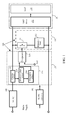
- FIG. 1 is a block diagram illustrating an application circuit 100 according to embodiments of the present disclosure.
- the application circuit 100 comprises a dynamic load circuit 110 and a control circuit 120.
- the dynamic load circuit 110 is electrically connected to the light source 130
- the control circuit 120 is electrically connected to the dynamic load circuit 110 and the TRAIC 140
- an AC/DC converter 150 is electrically connected to the control circuit 120.
- the light source 130 comprises at least one light-emitting diode (LED) 131 and a light-emitting diode driver (LED driver) 132.
- the light-emitting diode driver 132 is configured to drive the LED 131.
- the application circuit of the present disclosure is suitable for use in light-emitting diode drivers of various types and not limited to the circuits from different brands or manufactures.
- the brightness of the LED 131 is adjustable, and the application of the LED 131 in the light source system has become the mainstream trend of the industry; however, it shall be used together with the TRAIC 140, and hence, the application circuit 100 of the present disclosure provides a good adjustment mechanism for achieving a better brightness control effect.
- the AC/DC converter 150 converts the mains supply into DC source for the control circuit 120
- the TRAIC 140 receives the mains supply and inputs the current to the control circuit 120
- the control circuit 120 is configured to control the load status of the dynamic load circuit 120 based on the output current from the TRAIC 140.
- the present disclosure maintains the output current by the addition of a dynamic load control so as to turn on the light source 130 and enhance the lighting quality.
- the dynamic load circuit 110 comprises a switching element 111 and a dynamic load 112.
- the switching element 111 and the dynamic load 112 are in series connection with each other, wherein the switching element 111 is connected to one terminal of the light source 130, and the dynamic load 112 is connected to the other terminal of the light source 130.
- the dynamic load 112 may be a resistor or an impedance component consisting of metal oxide semiconductor(s).
- the on/off state of the switching element 111 is under the control of the control circuit 120.
- the control circuit 120 comprises a detecting unit 121 and a comparator 126.
- the TRAIC 140 is electrically connected to the detecting unit 121
- the detecting unit 121 is electrically connected to the comparator 126.
- the detecting unit 121 is configured to detect the output current from the TRAIC 140, and convert the output current into a voltage signal
- the comparator 126 is configured to compare the voltage signal with a minimum default conduction signal (Vref),and turn on or turn off the switching element 111 based on the comparison result.
- the user may set the minimum conduction signal (Vref) based on the turn-on angle of a required minimum-starting angle.
- the comparator 126 In the case where the voltage signal is less than the minimum default conduction signal, which means that it is a small turn-on angle or the TRAIC 140 is cut off, the comparator 126 outputs an trigger signal to turn on the switching element 111, such that the dynamic load 112 and the light source 130 are in parallel connection, thereby allowing the light source 130 to be lit under a small turn-on angle, so as to match the operating mode of conventional light bulbs.
- the turn-on angle has been improved from the original 107 degrees to 78.4 degrees, which is quite close to the starting angle of 76 degrees required for conventional halogen bulbs.
- the comparator 126 outputs an closed signal 111 to cut off the switching element 111, thereby excluding said dynamic load 112 and reduces the energy consumption.
- the detecting unit 121 comprises a current sensor 122, an absolute-value circuit 123 and an integrating circuit 124.
- the TRAIC 140 is electrically connected to the current sensor 122
- the current sensor 122 is electrically connected to the absolute-value circuit 123
- the absolute-value circuit 123 is electrically connected to integrating circuit 124.
- the current sensor 122 is configured to sense the output current of the TRAIC 140, wherein the output current is an alternating current wave form signal
- the absolute-value circuit 123 is configured to convert the alternating current wave form signal into a positive wave form signal
- the integrating circuit 124 is configured to convert the positive wave form signal into a direct current voltage for use as the voltage signal.
- the detecting unit 121 may be formed by other circuits, and persons having ordinary skill in the art may flexibly choose it depending on actual need(s).
- FIG. 2 is a flow chart illustrating a control method 200 of the application circuit 100 according to one embodiment of the present disclosure.
- the control method 200 comprises steps 210-220. It should be appreciated that the steps are not recited in the sequence in which the steps are performed. That is, unless the sequence of the steps is expressly indicated, the sequence of the steps is interchangeable, and all or part of the steps may be simultaneously, partially simultaneously, or sequentially performed. Also, the hardware devices for implementing these steps have been specifically disclosed in the above embodiments, and hence, detailed description thereof is omitted herein for the sake of brevity.
- the control method 200 could be the function performed by the control circuit 120 of Figure 1 , which is primarily based on the output current of the TRAIC 140 to control the load status of the dynamic load circuit 120, so as to turn on the light source 130.
- the present disclosure by the addition of a dynamic load control mode to maintain the output current, allows the user to turn on the light source 130 and improve the lighting quality.
- the output current from the TRIAC is detected, and the output current is converted into a voltage signal; next, in the step 220, the voltage signal is compared with a minimum default conduction signal, and the switching element is turned on or turned off based on the comparison result.
- the user may set the minimum trigger signal based on the turn-on angle required for setting the minimum starting angle.
- the step 210 may comprise: sensing the output current from the TRIAC, wherein the output current is an alternating current wave form signal; converting the alternating current wave form signal into a positive wave form signal; and converting the positive wave form signal into a direct current voltage for use as the voltage signal.
- the step 220 may comprises: when the voltage signal is less than a minimum default conduction signal, outputting a trigger signal to turn on the switching element, such that the dynamic load and the light source are in parallel connection, thereby allowing the light source 130 to be lit under a small turn-on angle, so as to match the operating mode of conventional light bulbs.
- the step 220 may comprise: when the voltage signal is greater than the minimum default conduction signal, outputting a closed signal to cut off the switching element, thereby excluding said dynamic load and reduces the energy consumption.
- the present invention focuses on improving the function of the light source circuit (e.g., an LED drive circuit) originally supporting the triode for alternating current.
- the present disclosure has the following advantageous characteristics: 1. Increasing a dynamic load circuit to allow the turning on of the light source (e.g., LED) under a small turn-on angle, so that the operation mode thereof matches the conventional bulbs; 2. When the switch is not turned on or under a small turn-on angle, increasing a dynamic load control mode to maintain the input circuit, thereby improving the lighting quality; 3.
- the triode for alternating current when under a high turn-on angle, uses the switching element to exclude such dynamic load, so as to reduce the energy consumption; 4. Since it is disposed on the input terminal of the mains supply, it is suitable to support various light-emitting diode drivers, and is not limited to circuits from any brands and/or manufacturers.
Landscapes
- Circuit Arrangement For Electric Light Sources In General (AREA)
Applications Claiming Priority (1)
| Application Number | Priority Date | Filing Date | Title |
|---|---|---|---|
| TW102118531A TW201446072A (zh) | 2013-05-24 | 2013-05-24 | 應用電路及其控制方法 |
Publications (1)
| Publication Number | Publication Date |
|---|---|
| EP2806712A1 true EP2806712A1 (de) | 2014-11-26 |
Family
ID=50972430
Family Applications (1)
| Application Number | Title | Priority Date | Filing Date |
|---|---|---|---|
| EP14168421.7A Withdrawn EP2806712A1 (de) | 2013-05-24 | 2014-05-15 | Anwendungsschaltung und Steuerverfahren dafür |
Country Status (3)
| Country | Link |
|---|---|
| US (1) | US20140346964A1 (de) |
| EP (1) | EP2806712A1 (de) |
| TW (1) | TW201446072A (de) |
Families Citing this family (2)
| Publication number | Priority date | Publication date | Assignee | Title |
|---|---|---|---|---|
| CN104883799B (zh) * | 2015-06-12 | 2018-11-23 | 昂宝电子(上海)有限公司 | 用于led驱动的控制方法、控制电路、系统及led灯具 |
| CN105101538B (zh) * | 2015-07-08 | 2018-10-23 | 浙江生辉照明有限公司 | 可控硅电流保护电路和方法、调光电路及照明设备 |
Citations (4)
| Publication number | Priority date | Publication date | Assignee | Title |
|---|---|---|---|---|
| WO2011114261A1 (en) * | 2010-03-17 | 2011-09-22 | Koninklijke Philips Electronics N.V. | Led unit for cooperation with a mains dimmer |
| US20120104970A1 (en) * | 2010-10-28 | 2012-05-03 | Mitsumi Electric Co., Ltd. | Lighting power supply device and method for controlling holding current |
| EP2482439A2 (de) * | 2011-01-26 | 2012-08-01 | Macroblock, Inc. | Adaptive Ableitschaltung |
| EP2544512A1 (de) * | 2011-07-06 | 2013-01-09 | Macroblock, Inc. | Haltestromschaltung mit automatischer Auswahl |
Family Cites Families (5)
| Publication number | Priority date | Publication date | Assignee | Title |
|---|---|---|---|---|
| JP2011165394A (ja) * | 2010-02-05 | 2011-08-25 | Sharp Corp | Led駆動回路、調光装置、led照明灯具、led照明機器、及びled照明システム |
| US8508147B2 (en) * | 2010-06-01 | 2013-08-13 | United Power Research Technology Corp. | Dimmer circuit applicable for LED device and control method thereof |
| US8698407B1 (en) * | 2011-11-14 | 2014-04-15 | Technical Consumer Products, Inc. | Highly integrated non-inductive LED driver |
| US20130175931A1 (en) * | 2012-01-05 | 2013-07-11 | Laurence P. Sadwick | Triac Dimming Control System |
| US9288864B2 (en) * | 2012-12-10 | 2016-03-15 | Dialog Semiconductor Inc. | Adaptive holding current control for LED dimmer |
-
2013
- 2013-05-24 TW TW102118531A patent/TW201446072A/zh unknown
-
2014
- 2014-02-06 US US14/173,823 patent/US20140346964A1/en not_active Abandoned
- 2014-05-15 EP EP14168421.7A patent/EP2806712A1/de not_active Withdrawn
Patent Citations (4)
| Publication number | Priority date | Publication date | Assignee | Title |
|---|---|---|---|---|
| WO2011114261A1 (en) * | 2010-03-17 | 2011-09-22 | Koninklijke Philips Electronics N.V. | Led unit for cooperation with a mains dimmer |
| US20120104970A1 (en) * | 2010-10-28 | 2012-05-03 | Mitsumi Electric Co., Ltd. | Lighting power supply device and method for controlling holding current |
| EP2482439A2 (de) * | 2011-01-26 | 2012-08-01 | Macroblock, Inc. | Adaptive Ableitschaltung |
| EP2544512A1 (de) * | 2011-07-06 | 2013-01-09 | Macroblock, Inc. | Haltestromschaltung mit automatischer Auswahl |
Also Published As
| Publication number | Publication date |
|---|---|
| TW201446072A (zh) | 2014-12-01 |
| US20140346964A1 (en) | 2014-11-27 |
Similar Documents
| Publication | Publication Date | Title |
|---|---|---|
| US10887957B2 (en) | Light emitting diode drive circuit with silicon-controlled rectifier dimmer, circuit module and control method | |
| US10433384B2 (en) | LED driver with silicon controlled dimmer, apparatus and control method thereof | |
| US11317483B2 (en) | Apparatus, dimmable light emitting diode drive circuit and control method | |
| EP1882396B1 (de) | Dimmer mit stromversorgungs-überwachungsschaltung | |
| US8508147B2 (en) | Dimmer circuit applicable for LED device and control method thereof | |
| JP5746311B2 (ja) | Led調光器のための適応可能な保持電流制御 | |
| US9936547B2 (en) | Multi-mode control for solid state lighting | |
| EP2277359B1 (de) | Dim bereichserweiterung für eine led-treiberschaltung verbunden mit einem phase-cut-dimmer | |
| CN104470055B (zh) | 点亮设备以及使用该点亮设备的照明系统 | |
| US20200178372A1 (en) | Load control device configured to operate in two-wire and three-wire modes | |
| US9801247B2 (en) | Light-dimming device | |
| JP2007227376A (ja) | 調光蛍光灯およびその回路 | |
| US8698416B2 (en) | Continuous dimming AC LED device | |
| JP4305308B2 (ja) | 調光装置 | |
| KR101226718B1 (ko) | 조명 기기의 밝기 제어 장치 및 그 제어 방법 | |
| EP2806712A1 (de) | Anwendungsschaltung und Steuerverfahren dafür | |
| JP2019061802A (ja) | 照明制御システム、点灯システム、照明システム、及びプログラム | |
| US8569968B2 (en) | Method for adjusting light brightness using a toggle switch and related illuminant system | |
| JP6618014B2 (ja) | 調光装置及び照明制御システム | |
| JP2017084623A (ja) | 調光装置 | |
| CN119300206A (zh) | 调光装置、用于控制调光装置的方法和存储介质 | |
| US10462863B2 (en) | Dimmer interface having reduced power consumption | |
| CN119300205A (zh) | 调光装置、用于控制调光装置的方法和存储介质 | |
| JP2017084622A (ja) | 調光装置 | |
| JP2018056100A (ja) | Led照明装置 |
Legal Events
| Date | Code | Title | Description |
|---|---|---|---|
| PUAI | Public reference made under article 153(3) epc to a published international application that has entered the european phase |
Free format text: ORIGINAL CODE: 0009012 |
|
| 17P | Request for examination filed |
Effective date: 20140515 |
|
| AK | Designated contracting states |
Kind code of ref document: A1 Designated state(s): AL AT BE BG CH CY CZ DE DK EE ES FI FR GB GR HR HU IE IS IT LI LT LU LV MC MK MT NL NO PL PT RO RS SE SI SK SM TR |
|
| AX | Request for extension of the european patent |
Extension state: BA ME |
|
| STAA | Information on the status of an ep patent application or granted ep patent |
Free format text: STATUS: THE APPLICATION IS DEEMED TO BE WITHDRAWN |
|
| 18D | Application deemed to be withdrawn |
Effective date: 20150527 |