EP2806723B1 - Rasenpositioniermaschine - Google Patents
Rasenpositioniermaschine Download PDFInfo
- Publication number
- EP2806723B1 EP2806723B1 EP13741260.7A EP13741260A EP2806723B1 EP 2806723 B1 EP2806723 B1 EP 2806723B1 EP 13741260 A EP13741260 A EP 13741260A EP 2806723 B1 EP2806723 B1 EP 2806723B1
- Authority
- EP
- European Patent Office
- Prior art keywords
- pushing plate
- sod
- vehicle
- base frame
- pair
- Prior art date
- Legal status (The legal status is an assumption and is not a legal conclusion. Google has not performed a legal analysis and makes no representation as to the accuracy of the status listed.)
- Active
Links
Images


Classifications
-
- A—HUMAN NECESSITIES
- A01—AGRICULTURE; FORESTRY; ANIMAL HUSBANDRY; HUNTING; TRAPPING; FISHING
- A01G—HORTICULTURE; CULTIVATION OF VEGETABLES, FLOWERS, RICE, FRUIT, VINES, HOPS OR SEAWEED; FORESTRY; WATERING
- A01G20/00—Cultivation of turf, lawn or the like; Apparatus or methods therefor
- A01G20/10—Pre-cultivated sod or turf; Apparatus therefor
- A01G20/18—Apparatus for laying sods or turfs
-
- A—HUMAN NECESSITIES
- A01—AGRICULTURE; FORESTRY; ANIMAL HUSBANDRY; HUNTING; TRAPPING; FISHING
- A01B—SOIL WORKING IN AGRICULTURE OR FORESTRY; PARTS, DETAILS, OR ACCESSORIES OF AGRICULTURAL MACHINES OR IMPLEMENTS, IN GENERAL
- A01B45/00—Machines for treating meadows or lawns, e.g. for sports grounds
Definitions
- FR 2 716 33 A1 discloses a system for laying pre-cultivated grass bands.
- the system comprises a chassis with a tractor drive for propelling it on the ground surface onto which the grass is to be unrolled.
- a support for the grass roll is mounted on the chassis and a chute for unrolling it at the same speed as the chassis is placed behind the chassis and inclined towards the ground.
- the chute which guides the grass onto the ground during its unrolling is pivoted around an axis perpendicular to the emptying plane. This allows modifying the orientation or final position of the band and allowing unrolling side by side in a systematic manner.
- a guide runner placed on one side of the chute pivots about a vertical axis and has a contact face in permanent contact with the adjacent band previously unrolled.
- the present inventor has recognized that using traction force from a vehicle to push sod strips can be undesirable because of the detrimental effect of the vehicle tires have on the un-sodded bare ground that supports the tires of the vehicle.
- the traction between tire and ground required for the vehicle to push the sod strip can cause ruts under the tires of the vehicle in the sand bed that awaits subsequently laid sod strips. This causes additional preparation work.
- the vehicle since the vehicle must be driven perpendicularly to the longitudinal strip direction, the vehicle must be constantly reoriented from strip to strip which also can cause ruts and unevenness in the sand or earth bed that awaits subsequently laid sod strips.
- the present inventor has recognized that it would be desirable to provide a machine that accomplished the task of laterally positioning sod strips, already laid out flat on the ground, to tightly pack adjacent strips to minimize or eliminate gaps in the seams of adjacent sod strips.
- the exemplary device of the invention provides an attachment or enhancement to a sod placement machine or other vehicle that comprises a pushing apparatus for pushing a sod strip that is already placed on the ground, tightly against an adjacent sod strip that is already placed on the ground, as disclosed in claim 1. This action tightens up the seams between sod strips.
- the enhancement includes a stationary frame carried by the vehicle and a laterally sliding frame carried by the stationary frame. A pair of hydraulic or pneumatic cylinders are arranged to pivot the frames up or down between a deployed position and a stand-by or traveling position.
- the device includes a pair of hydraulic or pneumatic cylinders that are operable to slide the laterally sliding frame in a direction away from the stationary frame to push a sod strip, or toward the stationary frame to retract the laterally sliding frame closer to the vehicle for transport to a subsequent sod strip to be pushed.
- the laterally sliding frame includes a pair of sliding box beams that telescopically retract into box beams of the stationary frame.
- the sliding beams mount a pushing plate that abuts the sod strip during a pushing operation.
- the sod positioning apparatus pushes the sod strips laid end-to-end to have a common straight line longitudinal edge. This increases the efficiency of the sod laying process. Also, by laterally pressing the sod strip using the apparatus of the invention, the sod strip is compressed and the density of sod increases. For example, a 42 inch (106,68 cm) wide sod strip can be compressed to 40 inches (101,6 cm) wide during positioning.
- An alternate pushing plate comprises spikes extending from a bottom of the plate for use is pushing sod strips that are surrounded by sod or other obstacles that prevents exposing a side edge of the sod strip.
- the plate can be placed over the sod and penetration of the spikes into the sod strip creates a gripping that can be used to laterally shift the sod using the apparatus of the present invention.
- Figure 1 illustrates a few strips 20 of sod that have been laid in a longitudinal direction L of the sod strips onto a bed 26 of sand or the like.
- a most recently laid strip 20a is shown being pushed in the lateral direction P by a vehicle 30, such as a "skid steer" loader or the like in order to tighten up the packing of the adjacent strips, i.e., to close or minimize the seam or gap 31.
- the vehicle 30 is driven by wheels and tires 36 that achieve forward traction force in the direction P by the interaction between the tires 36 and the bed 26. This interaction can cause ruts or other irregularities in the bed which must be smoothed before a subsequent strip 20b (shown dashed) is placed on the bed 26.
- a future strip to be laid is shown dashed as 20c.
- the vehicle 30 In order for the vehicle 30 to be positioned against the strip 20c to push in the lateral direction P, in practical terms, the vehicle must turned, driven and reoriented. This also can cause ruts or other irregularities in the bed which must be smoothed before a subsequent strip 20b (shown dashed) is placed on the bed 26.
- FIGS 2-4 illustrate an apparatus 50 that overcomes the drawbacks of the prior method.
- the apparatus 50 includes an attachment or enhancement sod positioning apparatus 60 that is mounted on a vehicle 66.
- the vehicle 66 can be a sod placement vehicle such as described in U.S. Patent 6,213,218 .
- the vehicle 66 comprises a chassis frame 68 that is supported on six traction wheels and tires 70, at least one of which is driven by an engine and drivetrain (not shown).
- the vehicle can also provide a source (not shown) of controllable hydraulic or pneumatic pressurized working fluid to operate the apparatus 60, such as a compressor or pump and associated controls.
- the frame 68 includes a bay 74 in which a spindle 75 is mounted on a fork frame 76 that is used to hold and unroll sod rolls during placement of the sod strips onto the bed 26.
- the fork frame 76 is controlled to pivot up or down depending on the degree of depletion of sod on a sod roll.
- a hydraulic cylinder 67a is connected between a stationary post 67b on the chassis frame 68 and a cross beam 76a of the frame 76.
- the frame is pivotal about an axis defined by two aligned pivot connections 76c (only one visible in Figure 4 ).
- Sod installation machine frame can be expanded to accommodate sod rolls of different widths, such as 30 inches (76,2 cm), 42inches (106,68 cm), 48 inches (121,92 cm)and 52inches (132,08 cm).
- the vehicle can be driven by a plurality of hydraulic motors, such as one per each wheel, or other known traction drive.
- the vehicle can include a hydraulic oil system that drives the traction motors, controls steering, and raises and lowers the fork frame and spindle that holds a sod roll, all controlled at an operators station 77.
- a hydraulic oil pump 79 Also mounted on the chassis frame 68 is a hydraulic oil pump 79 and a fuel tank 81 ( Figure 4 ).
- the apparatus 60 comprises two posts 78, 80 that are fixedly mounted to the frame 68 at a rear and front respectively of the near side of the vehicle, such as by fasteners or welding.
- a substantially U-shaped base frame 90 comprises rear and front base tubes 94, 96 respectively.
- the base tubes 94, 96 can have a square cross section and are hollow.
- a longitudinal brace tube 100 connects the rear and front tubes 78, 80.
- the rear and front base tubes 94, 96 have open ends 94a, 96a, respectively.
- the front tube 96 is connected at a low position to the post 80 by a pin connection 106 to a pair of lugs 80a to allow pivoting of the tube 96 with respect to the post 80.
- the rear tube 94 is connected at a low position to the post 78 by a pin connection (not visible in Fig. 2 ) to allow pivoting of the tube 94 with respect to the post 78, in an identical fashion as the front tube 96 is pivotally connected to the front post 80.
- the frame 90 is supported from the posts 78, 80 by a pair of actuators, such as hydraulic or pneumatic cylinders, a rear cylinder 110 and a front cylinder 112.
- the rear cylinder is pivotally connected to an upper position on the post 78 by a pin connection 110a to a lug 78a.
- the cylinder 110 is also connected to a lug 94b on the tube 94 by a pin connection 110b.
- the front cylinder is pivotally connected to an upper position on the post 80 by a pin connection 112a to a lug 80b.
- the cylinder 112 is also connected to a lug 96b on the tube 96 by a pin connection 112b.
- the cylinders 110, 112 By hydraulic or pneumatic pressure control of the working fluid into select ports of the cylinders 110, 112, the cylinders can be made to work in unison to contract or elongate which will either pivot the frame 90 up or pivot the frame 90 down with respect to the posts 78, 80.
- the flow of pressurized fluid to the cylinders is maintained uniform through pressure regulating valves, enhancing performance.
- a pushing frame 150 is carried by the base frame 90.
- the pushing frame 150 comprises rear and front arm tubes 156, 158.
- the arm tubes 156, 158 are shaped and sized to slidably and telescopically fit into the open ends 94a, 96a of the base tubes 94, 96 and to slide into the base tubes 94, 96, respectively.
- a front of each of the arm tubes 156, 158 is connected to a pusher plate 170 via lugs 172, 174 by pin connections 156a and 158a.
- the plate 170 has a bottom wall 178 and an upturned front wall 180.
- a rear hydraulic or pneumatic cylinder 202 is mounted between the arm tube 156 and the base tube 94.
- a front hydraulic or pneumatic cylinder 206 is mounted between the arm tube 158 and the base tube 96. Since the rear hydraulic tube is less visible in Figure 2 , the mounting of the front cylinder 206 will be described with the understanding that the rear cylinder 202 is mounted in identical fashion to the arm tube 156 and the base tube 94, as the front cylinder 206 is mounted to the arm tube 158 and the base tube 96.
- One end of the cylinder 206 is connected by a pin connection 206a to the arm tube 158 via a lug 158b extending on a bottom side of the arm 158 and an opposite end of the cylinder 206 is connected by a pin connection 206b to the base tube 96 via a lug 96b extending on a bottom side of the base tube 96.
- the cylinders can be made to work in unison to contract or elongate, which will either slide the tube arms 156, 158 in a direction out of the base tubes 94, 96 or retract the tube arms 156, 158 into the base tubes 94, 96.
- the flow of pressurized fluid to the cylinders is maintained uniform through pressure regulating valves, enhancing performance.
- Figure 4 also shows a stop assembly 216 comprising a threaded tube or threaded ferrule 217 welded to the bottom wall 178 and a bolt 218 adjustably threaded into the ferrule 217.
- the head 218a of the bolt 218 abuts the underside of the arm 158 if during positioning of the sod strip by hydraulic pressure from the cylinders 110, 112, 202, 206 the plate 170 tips up in the back.
- the adjustable degree of permissible tipping is selected by the vertical position of the head 218a that is selected by the degree of vertical threaded engagement of the bolt 218 into the ferrule 217.
- An identical stop assembly 216 can be arranged in similar fashion between the bottom wall 178 and the arm 156.
- a plurality of "suitcase weights" or removable weights 220 are shown in Figures 3 and 4 installed onto the spindle 75.
- the weights 220 provide for an increased bracing force or reaction force via the tires of the vehicle during use of the cylinders 202, 206 to push against a sod strip to shift the sod strip laterally or compress the sod strip laterally.
- a heavy sod roll can be carried on the spindle.
- hydraulic or pneumatic cylinders 110, 112, 202, 206 are mentioned, it is within the scope of the invention that other actuators can be used, such as electrically driven actuators.
- the apparatus 60 By retracting the cylinders 110, 112, 202, 206, the apparatus 60 can be folded up and the vehicle used for another purpose.
- the upturned front wall 180 of the pusher plate 170 can be pushed against the sod edge for positioning.
- a selectable removable strip or plate can be provided that is fastened or otherwise secured to the bottom wall 178 or to the upturned front wall 180 to accommodate pushing sod of varying thickness, such as 1 inches to 5 inches, that best matches the thickness of the sod being installed.
- the removable strip or plate can attach to the plate 170 and run the length of the plate 170. In some circumstances, the plate 170 works best when the bottom wall 178 lays flat against the bare ground for ease of operation and visibility for the operator, causing little or no disruption the existing grade or ground. Different plates 170 can be attached to the arms 156, 158 to accommodate different situations.
- a 4 inch thick sod requires a wider upturned front wall 180, or an attached strip, as well as a wider bottom wall 178, wider in the direction P, providing a larger flat area to use the ground as leverage while pushing.
- Other plates can also be used.
- the plate 170 pivots at pin connections 156a and 158a which is effective for ground pressure control and allowing for angle positioning of the plate 170, depending on the terrain.
- a side edge upturned wall 181 is sloped or curved up, like a ski or sled to accommodate pushing or sliding along the ground when the machine moves in the direction V, with minimal disruption to the ground and reduces the need to lift the apparatus 60 for repositioning.
- the apparatus 60 can be folded up more completely by detaching the connections 110b and 112b and folding the frames 90, 150 up to the posts 78, 80 and securing thereto.
- connections 106, 156a, 158a and similar pivotal connections or joints can comprise a through pin 280 and two engageable hairpin-shaped retainer wires 282 which insert into end pin holes through the through pin, for quick disconnect of the connection, as shown for connection 106 in Figure 4 .
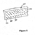
- an alternate plate 300 that can replace the plate 170 shown in Figure 2 can have spaced apart spikes 320 over its bottom surface, which extend downwardly in perpendicular fashion from a bottom wall 322.
- the spikes 320 can be 1.5 inch long spikes.
- the spikes 320 are useful for pushing sod in a repair area in the middle of a sod area, where there is no exposed vertical edge of the sod strip to push with a plate.
- the gripping of the spikes 320 into a top of the sod strip gives the apparatus 60 a grip on the sod strip to exert a pushing force in the direction P with respect to the apparatus 60.
Landscapes
- Life Sciences & Earth Sciences (AREA)
- Environmental Sciences (AREA)
- Engineering & Computer Science (AREA)
- Mechanical Engineering (AREA)
- Soil Sciences (AREA)
- Placing Or Removing Of Piles Or Sheet Piles, Or Accessories Thereof (AREA)
- Forklifts And Lifting Vehicles (AREA)
- Vehicle Cleaning, Maintenance, Repair, Refitting, And Outriggers (AREA)
- Protection Of Plants (AREA)
- Road Paving Machines (AREA)
Claims (15)
- Vorrichtung (60) zum Positionieren von Rasenstreifen, umfassend:eine Struktur (78, 80, 90) zur Montage an einem Fahrzeug;eine Schubplatte (170), die verschiebbar an der Struktur angebracht ist, wobei die Schubplatte (170) eine Bodenwand (178) und eine nach oben gerichtete Vorderwand (180) aufweist, die so angeordnet ist, dass sie an einer vertikalen Kante eines bereits flach auf den Boden gelegten Rasenstreifens anliegen kann; undmindestens ein Stellglied (202, 206), das funktionsfähig zwischen der Struktur (78, 80, 90) und der Schubplatte (170) angebracht ist, um die Schubplatte von der Struktur weg zu schieben, um den Rasenstreifen zu positionieren, wobei das Betätigungselement (202, 206) und die Schubplatte (170) so angeordnet sind, dass die Schubplatte (170) in einer seitlichen Richtung gleitet, die senkrecht zur Geradeausfahrtrichtung des Fahrzeugs ist, und den Rasenstreifen seitlich zusammendrückt.
- Vorrichtung nach Anspruch 1, umfassend einen Schieberahmen (150), der die Schubplatte (170) trägt, wobei der Schieberahmen (150) Arme (156, 158) zwischen der Schubplatte (170) und der Struktur (78, 80, 90) aufweist; und
die Struktur einen Basisrahmen (90) umfasst, wobei der Basisrahmen Basisrohre (94, 96) aufweist, die sich von dem Fahrzeug in Richtung der Schubplatte erstrecken, wobei jeder Arm (156, 158) gleitend in einem jeweiligen Basisrohr aufgenommen ist, und das mindestens eine Stellglied (202, 206) ein Paar von Stellgliedern umfasst, von denen einer zwischen jedem Arm und jedem jeweiligen Basisrohr angebracht ist. - Vorrichtung nach Anspruch 2, wobei die Struktur ein Paar aufrechtstehender Pfosten (78, 80) umfasst, die so konfiguriert sind, dass sie an dem Fahrzeug (66) angebracht werden können, wobei der Basisrahmen (90) von dem Pfostenpaar getragen wird.
- Vorrichtung nach Anspruch 3, wobei der Basisrahmen (90) schwenkbar mit den Pfosten verbunden ist und mindestens einen Schwenkaktuator (110, 112) umfasst, der so konfiguriert ist, dass er den Basisrahmen (90) steuerbar nach oben oder unten schwenkt.
- Vorrichtung nach Anspruch 4, wobei der mindestens eine Schwenkaktuator ein Paar von Schwenkaktuatoren umfasst, die betriebsmäßig zwischen dem Paar von Pfosten und den Basisrohren des Basisrahmens verbunden sind.
- Vorrichtung nach Anspruch 1, die ferner ein Fahrzeug (66) zur Bewegung auf dem Boden umfasst, wobei die Struktur (78, 80, 90) an dem Fahrzeug (66) angebracht ist.
- Vorrichtung nach Anspruch 2 und 6, wobei die Struktur (78, 80, 90) ein Paar aufrecht stehender Pfosten (78, 80), die so konfiguriert sind, dass sie an dem Fahrzeug (66) angebracht werden können, und einen Basisrahmen (90) umfasst, wobei der Basisrahmen (90) die Gleitbewegung der Schubplatte (170) führt, wobei der Basisrahmen von dem Paar Pfosten (78, 80) getragen wird.
- Vorrichtung nach Anspruch 7, wobei der Basisrahmen (90) schwenkbar mit den Pfosten (78, 80) verbunden ist und mindestens einen Schwenkaktuator (110, 112) umfasst, der so konfiguriert ist, dass er den Basisrahmen (90) nach oben oder unten schwenken kann.
- Vorrichtung nach Anspruch 8, wobei der mindestens eine Schwenkaktuator ein Paar von Schwenkaktuatoren umfasst, die funktionsfähig zwischen dem Paar von Pfosten und den Basisrohren des Basisrahmens verbunden sind.
- Vorrichtung nach Anspruch 6, wobei das Fahrzeug (66) eine Rollrasenhalte- und -ausgabevorrichtung (75, 76) zum Halten und Ausgeben einer Rollrasenrolle zum Abrollen und Ablegen der Rollrasenrolle flach auf dem Boden umfasst.
- Vorrichtung nach Anspruch 10, dadurch gekennzeichnet, dass die Vorrichtung zum Halten und Ausgeben der Rollrasenrolle eine Spindel (75) umfasst, die von einem Gabelrahmen (76) getragen wird.
- Vorrichtung nach Anspruch 6, wobeia) das Fahrzeug einen Vorrat an unter Druck stehendem Arbeitsfluid aufweist und das Stellglied (202, 206) einen hydraulischen oder pneumatischen Zylinder umfasst, der den Vorrat an Arbeitsfluid nutzt, um die Schubplatte auszufahren und zu verschieben, oderb) das Stellglied (202, 206) und die Schubplatte (170) so angeordnet sind, dass die Schubplatte (170) in einer seitlichen Richtung gleitet, die senkrecht zur Geradeausfahrt des Fahrzeugs (66) verläuft.
- Vorrichtung nach Anspruch 6, umfassend einen Schieberahmen (150), der die Schubplatte (170) trägt, wobei der Schieberahmen Arme (156, 158) zwischen der Schubplatte (170) und der Struktur (78, 80, 90) aufweist; undwobei die Schubplatte eine Bodenwand (178) und eine aufwärts gerichtete Vorderwand (180) aufweist, die an die Bodenwand (178) angrenzt, wobei die aufwärts gerichtete Vorderwand so angeordnet ist, dass sie an einer vertikalen Kante eines zu positionierenden Rasenstreifens anliegt; undwobei die Arme und die Bodenwand durch ein Paar von Schwenkverbindungen (156a, 158a) verbunden sind.
- Vorrichtung nach Anspruch 13, wobeia) die Struktur (78, 80, 90) einen Basisrahmen (90) umfasst, wobei der Basisrahmen Grundrohre (94, 96) aufweist, die sich von dem Fahrzeug in Richtung der Schubplatte erstrecken, wobei jeder Arm (156, 158) gleitend in einem jeweiligen Grundrohr aufgenommen ist und der mindestens eine Aktuator ein Paar von Aktuatoren (202, 206) umfasst, von denen einer zwischen jedem Arm und jedem jeweiligen Grundrohr angebracht ist, undb) die Struktur ein Paar aufrecht stehender Pfosten (78, 80) umfasst, die so konfiguriert sind, dass sie an dem Fahrzeug (66) angebracht werden können, wobei der Basisrahmen (90) von dem Paar Pfosten getragen wird, und wobei der Basisrahmen schwenkbar mit den Pfosten verbunden ist und mindestens einen Schwenkaktuator (110, 112) umfasst, das so konfiguriert ist, dass es den Basisrahmen (90) steuerbar nach oben oder unten schwenkt.
- Vorrichtung nach Anspruch 1, wobeia) die Bodenwand der Schubplatte (300) eine nach unten weisende Oberfläche aufweist und eine Vielzahl von Stacheln (320) umfasst, die sich von der nach unten weisenden Oberfläche nach unten erstrecken, oderb) das mindestens eine Stellglied so konfiguriert ist, dass es die Schubplatte veranlasst, den Rasenstreifen seitlich von einer unkomprimierten Breite von 106,68 cm (42 Zoll) auf eine komprimierte Breite von 101,6 cm (40 Zoll) zu komprimieren.
Applications Claiming Priority (2)
| Application Number | Priority Date | Filing Date | Title |
|---|---|---|---|
| US13/358,143 US9028199B2 (en) | 2012-01-25 | 2012-01-25 | Sod positioning machine |
| PCT/US2013/023247 WO2013112904A1 (en) | 2012-01-25 | 2013-01-25 | Sod positioning machine |
Publications (3)
| Publication Number | Publication Date |
|---|---|
| EP2806723A1 EP2806723A1 (de) | 2014-12-03 |
| EP2806723A4 EP2806723A4 (de) | 2015-02-18 |
| EP2806723B1 true EP2806723B1 (de) | 2021-11-17 |
Family
ID=48796171
Family Applications (1)
| Application Number | Title | Priority Date | Filing Date |
|---|---|---|---|
| EP13741260.7A Active EP2806723B1 (de) | 2012-01-25 | 2013-01-25 | Rasenpositioniermaschine |
Country Status (5)
| Country | Link |
|---|---|
| US (1) | US9028199B2 (de) |
| EP (1) | EP2806723B1 (de) |
| AU (1) | AU2013211922B2 (de) |
| CA (1) | CA2862668C (de) |
| WO (1) | WO2013112904A1 (de) |
Families Citing this family (12)
| Publication number | Priority date | Publication date | Assignee | Title |
|---|---|---|---|---|
| US9565796B1 (en) * | 2012-01-12 | 2017-02-14 | Steve Bush | Top surface mover and method of use |
| US20150296717A1 (en) * | 2012-01-25 | 2015-10-22 | Sidekick USA, LLC | Sod Positioning Machine |
| US10117386B1 (en) * | 2013-06-20 | 2018-11-06 | Troy Wilson | Synthetic turf removal skid steer attachment assembly |
| HUE055853T2 (hu) | 2015-04-24 | 2022-01-28 | Sidekick Usa Llc | Gyepszõnyeg pozicionáló gép |
| CN108867609A (zh) * | 2018-07-23 | 2018-11-23 | 宁夏中卫市廙园机械装备研发有限公司 | 一种轻型草方格治沙机械装置 |
| CN109468925B (zh) * | 2018-11-14 | 2021-05-14 | 丁朝朝 | 一种园林绿化施工用人工草坪铺设装置 |
| CN110278834B (zh) * | 2019-07-23 | 2024-06-14 | 交通运输部科学研究院 | 一种表土与草皮块收集设备及其工作方法 |
| CN113455301A (zh) * | 2021-07-24 | 2021-10-01 | 沂水鸿羽环境科技中心 | 一种草原生态修复方法 |
| CN114258823B (zh) * | 2021-11-15 | 2023-08-08 | 安徽一丸生物科技有限公司 | 一种高适用性草块铺设装置 |
| IT202200007541A1 (it) * | 2022-04-14 | 2023-10-14 | Learco Galardini | Macchina accosta-prato |
| CN115362881B (zh) * | 2022-07-18 | 2023-09-26 | 南京航空航天大学 | 一种基于小型多连杆插草机构的草方格铺设车 |
| AU2024256073A1 (en) * | 2023-04-14 | 2025-11-27 | Paul Carlson | Selectable sod positioning machine |
Citations (2)
| Publication number | Priority date | Publication date | Assignee | Title |
|---|---|---|---|---|
| US3326592A (en) * | 1965-05-14 | 1967-06-20 | Donald B Pelton | Sod pick-up |
| US4777890A (en) * | 1986-04-25 | 1988-10-18 | Gabard Raymond | Machine for handling, assembling, laying, watering and pressing sod rolls |
Family Cites Families (24)
| Publication number | Priority date | Publication date | Assignee | Title |
|---|---|---|---|---|
| US2661708A (en) | 1946-06-12 | 1953-12-08 | Harrison V Pittman | Sod planting machine |
| US2713835A (en) | 1951-02-09 | 1955-07-26 | Harrison V Pittman | Sod-planting machine |
| US3924765A (en) | 1974-03-01 | 1975-12-09 | Dewey L Hostetler | Hydraulic side lift loader |
| US4067393A (en) | 1975-08-05 | 1978-01-10 | Szarkowski Raphael J | Method and apparatus for handling and laying strips of sod |
| US4149640A (en) | 1976-06-07 | 1979-04-17 | White John M | Means for laying sod |
| CA1138781A (en) | 1979-07-20 | 1983-01-04 | Brouwer Turf Equipment Limited | Automatic steering mechanism for sod processing machine and shoe therefor |
| US4408666A (en) | 1981-10-28 | 1983-10-11 | Lawson Charles L | Sod handling apparatus |
| US4632192A (en) | 1984-07-18 | 1986-12-30 | Hooks Thomas E | Multiple-unit apparatus for lifting sod |
| JPH04144605A (ja) | 1990-10-05 | 1992-05-19 | Kubota Corp | 芝張り機 |
| US5215278A (en) | 1991-12-02 | 1993-06-01 | Hess Douglas S | Apparatus for laying turf |
| US5230602A (en) | 1992-07-31 | 1993-07-27 | Schouten Ben H | Sod roll stacker |
| US5253970A (en) | 1992-08-13 | 1993-10-19 | Bashaw Iii William L | Round hay bale dispenser |
| US5307880A (en) | 1993-03-12 | 1994-05-03 | Woerner Edward E | Sod roll-out machine with endless tracks |
| FR2716333B1 (fr) | 1994-02-24 | 1996-04-26 | Fontainebleau Gazons | Dispositif de pose de gazon précultivé en bandes. |
| US5697452A (en) | 1995-12-05 | 1997-12-16 | American Roller Bushing Corporation | Sod roll laying apparatus and method |
| US5988289A (en) | 1997-08-04 | 1999-11-23 | Holland; Gregory Paul | Sod laying apparatus |
| US6131668A (en) | 1997-12-29 | 2000-10-17 | Clark Equipment Company | Sod laying apparatus and method |
| US6213218B1 (en) | 1998-10-22 | 2001-04-10 | Donald R. Miller | Sod laying apparatus |
| US6179060B1 (en) | 1999-05-25 | 2001-01-30 | Thomas E. Halter | Sod-laying vehicle apparatus and Sod-holding device therefor |
| US6663337B2 (en) | 2001-02-07 | 2003-12-16 | Westendorf Manufacturing Co., Inc. | Bale lift device, a front end loader having a bale lift device, and method for moving bales |
| US6550406B2 (en) | 2001-03-21 | 2003-04-22 | Anthony C. Bass | Sod roll installation device |
| US7673697B2 (en) | 2002-01-23 | 2010-03-09 | Jonathan Michael Peterson | Sod laying machine |
| US6913086B2 (en) | 2002-08-28 | 2005-07-05 | Timothy J. Stevens | Skimmer |
| CA2520167A1 (en) | 2004-09-23 | 2006-03-23 | 1045929 Ontario Limited | Machine for laying sod |
-
2012
- 2012-01-25 US US13/358,143 patent/US9028199B2/en active Active
-
2013
- 2013-01-25 AU AU2013211922A patent/AU2013211922B2/en active Active
- 2013-01-25 WO PCT/US2013/023247 patent/WO2013112904A1/en not_active Ceased
- 2013-01-25 CA CA2862668A patent/CA2862668C/en active Active
- 2013-01-25 EP EP13741260.7A patent/EP2806723B1/de active Active
Patent Citations (2)
| Publication number | Priority date | Publication date | Assignee | Title |
|---|---|---|---|---|
| US3326592A (en) * | 1965-05-14 | 1967-06-20 | Donald B Pelton | Sod pick-up |
| US4777890A (en) * | 1986-04-25 | 1988-10-18 | Gabard Raymond | Machine for handling, assembling, laying, watering and pressing sod rolls |
Also Published As
| Publication number | Publication date |
|---|---|
| US20130186314A1 (en) | 2013-07-25 |
| CA2862668A1 (en) | 2013-08-01 |
| AU2013211922A1 (en) | 2014-08-28 |
| WO2013112904A1 (en) | 2013-08-01 |
| CA2862668C (en) | 2018-11-20 |
| EP2806723A1 (de) | 2014-12-03 |
| EP2806723A4 (de) | 2015-02-18 |
| US9028199B2 (en) | 2015-05-12 |
| AU2013211922B2 (en) | 2017-02-23 |
Similar Documents
| Publication | Publication Date | Title |
|---|---|---|
| EP2806723B1 (de) | Rasenpositioniermaschine | |
| US10368500B2 (en) | Sod positioning machine | |
| US9605407B2 (en) | Apparatus with divergent V-wing blade configuration | |
| US7748789B2 (en) | Pavement profiler | |
| US7451757B2 (en) | Concrete cutter | |
| US10368501B2 (en) | Sod positioning machine with sod hold down member | |
| US10648139B2 (en) | Carriage suspended concrete drill gang assembly | |
| US20080205983A1 (en) | Slot cutting apparatus | |
| CN102650115A (zh) | 带有材料偏转板的筑路机 | |
| CN114352324B (zh) | 锚护机器人 | |
| US3724900A (en) | Concrete pavement cutting machine | |
| KR20120016042A (ko) | 벌크 재료를 운송하기 위한 보관 웨건 및 방법 | |
| US20240365725A1 (en) | Selectable sod positioning machine | |
| US2805847A (en) | Accessory impact mechanism for tractors | |
| US20050196240A1 (en) | Slot cutting apparatus and method | |
| US3572226A (en) | Apparatus for insertion of transverse joint former material | |
| WO2025217669A1 (en) | Skid steer attachment |
Legal Events
| Date | Code | Title | Description |
|---|---|---|---|
| PUAI | Public reference made under article 153(3) epc to a published international application that has entered the european phase |
Free format text: ORIGINAL CODE: 0009012 |
|
| 17P | Request for examination filed |
Effective date: 20140811 |
|
| AK | Designated contracting states |
Kind code of ref document: A1 Designated state(s): AL AT BE BG CH CY CZ DE DK EE ES FI FR GB GR HR HU IE IS IT LI LT LU LV MC MK MT NL NO PL PT RO RS SE SI SK SM TR |
|
| A4 | Supplementary search report drawn up and despatched |
Effective date: 20150119 |
|
| RIC1 | Information provided on ipc code assigned before grant |
Ipc: A01B 45/00 20060101AFI20150113BHEP Ipc: A01G 1/00 20060101ALI20150113BHEP |
|
| DAX | Request for extension of the european patent (deleted) | ||
| STAA | Information on the status of an ep patent application or granted ep patent |
Free format text: STATUS: EXAMINATION IS IN PROGRESS |
|
| 17Q | First examination report despatched |
Effective date: 20170418 |
|
| REG | Reference to a national code |
Ref country code: DE Ref legal event code: R079 Ref document number: 602013080086 Country of ref document: DE Free format text: PREVIOUS MAIN CLASS: A01B0045000000 Ipc: A01G0020180000 |
|
| RIC1 | Information provided on ipc code assigned before grant |
Ipc: A01G 20/18 20180101AFI20210210BHEP |
|
| GRAP | Despatch of communication of intention to grant a patent |
Free format text: ORIGINAL CODE: EPIDOSNIGR1 |
|
| STAA | Information on the status of an ep patent application or granted ep patent |
Free format text: STATUS: GRANT OF PATENT IS INTENDED |
|
| INTG | Intention to grant announced |
Effective date: 20210611 |
|
| GRAS | Grant fee paid |
Free format text: ORIGINAL CODE: EPIDOSNIGR3 |
|
| GRAA | (expected) grant |
Free format text: ORIGINAL CODE: 0009210 |
|
| STAA | Information on the status of an ep patent application or granted ep patent |
Free format text: STATUS: THE PATENT HAS BEEN GRANTED |
|
| AK | Designated contracting states |
Kind code of ref document: B1 Designated state(s): AL AT BE BG CH CY CZ DE DK EE ES FI FR GB GR HR HU IE IS IT LI LT LU LV MC MK MT NL NO PL PT RO RS SE SI SK SM TR |
|
| REG | Reference to a national code |
Ref country code: GB Ref legal event code: FG4D |
|
| REG | Reference to a national code |
Ref country code: IE Ref legal event code: FG4D |
|
| REG | Reference to a national code |
Ref country code: DE Ref legal event code: R096 Ref document number: 602013080086 Country of ref document: DE |
|
| REG | Reference to a national code |
Ref country code: AT Ref legal event code: REF Ref document number: 1447296 Country of ref document: AT Kind code of ref document: T Effective date: 20211215 |
|
| REG | Reference to a national code |
Ref country code: DE Ref legal event code: R081 Ref document number: 602013080086 Country of ref document: DE Owner name: SIDEKICK USA, LLC, PLAINFIELD, US Free format text: FORMER OWNER: LAWNS KEEPER INC., PLAINFIELD, IL, US |
|
| REG | Reference to a national code |
Ref country code: NL Ref legal event code: FP |
|
| RAP2 | Party data changed (patent owner data changed or rights of a patent transferred) |
Owner name: SIDEKICK USA, LLC |
|
| REG | Reference to a national code |
Ref country code: LT Ref legal event code: MG9D |
|
| REG | Reference to a national code |
Ref country code: GB Ref legal event code: 732E Free format text: REGISTERED BETWEEN 20220217 AND 20220223 |
|
| REG | Reference to a national code |
Ref country code: NL Ref legal event code: PD Owner name: SIDEKICK USA, LLC; US Free format text: DETAILS ASSIGNMENT: CHANGE OF OWNER(S), ASSIGNMENT; FORMER OWNER NAME: LAWNS KEEPER INC. Effective date: 20220214 |
|
| REG | Reference to a national code |
Ref country code: AT Ref legal event code: MK05 Ref document number: 1447296 Country of ref document: AT Kind code of ref document: T Effective date: 20211117 |
|
| PG25 | Lapsed in a contracting state [announced via postgrant information from national office to epo] |
Ref country code: RS Free format text: LAPSE BECAUSE OF FAILURE TO SUBMIT A TRANSLATION OF THE DESCRIPTION OR TO PAY THE FEE WITHIN THE PRESCRIBED TIME-LIMIT Effective date: 20211117 Ref country code: LT Free format text: LAPSE BECAUSE OF FAILURE TO SUBMIT A TRANSLATION OF THE DESCRIPTION OR TO PAY THE FEE WITHIN THE PRESCRIBED TIME-LIMIT Effective date: 20211117 Ref country code: FI Free format text: LAPSE BECAUSE OF FAILURE TO SUBMIT A TRANSLATION OF THE DESCRIPTION OR TO PAY THE FEE WITHIN THE PRESCRIBED TIME-LIMIT Effective date: 20211117 Ref country code: BG Free format text: LAPSE BECAUSE OF FAILURE TO SUBMIT A TRANSLATION OF THE DESCRIPTION OR TO PAY THE FEE WITHIN THE PRESCRIBED TIME-LIMIT Effective date: 20220217 Ref country code: AT Free format text: LAPSE BECAUSE OF FAILURE TO SUBMIT A TRANSLATION OF THE DESCRIPTION OR TO PAY THE FEE WITHIN THE PRESCRIBED TIME-LIMIT Effective date: 20211117 |
|
| PG25 | Lapsed in a contracting state [announced via postgrant information from national office to epo] |
Ref country code: IS Free format text: LAPSE BECAUSE OF FAILURE TO SUBMIT A TRANSLATION OF THE DESCRIPTION OR TO PAY THE FEE WITHIN THE PRESCRIBED TIME-LIMIT Effective date: 20220317 Ref country code: SE Free format text: LAPSE BECAUSE OF FAILURE TO SUBMIT A TRANSLATION OF THE DESCRIPTION OR TO PAY THE FEE WITHIN THE PRESCRIBED TIME-LIMIT Effective date: 20211117 Ref country code: PT Free format text: LAPSE BECAUSE OF FAILURE TO SUBMIT A TRANSLATION OF THE DESCRIPTION OR TO PAY THE FEE WITHIN THE PRESCRIBED TIME-LIMIT Effective date: 20220317 Ref country code: PL Free format text: LAPSE BECAUSE OF FAILURE TO SUBMIT A TRANSLATION OF THE DESCRIPTION OR TO PAY THE FEE WITHIN THE PRESCRIBED TIME-LIMIT Effective date: 20211117 Ref country code: NO Free format text: LAPSE BECAUSE OF FAILURE TO SUBMIT A TRANSLATION OF THE DESCRIPTION OR TO PAY THE FEE WITHIN THE PRESCRIBED TIME-LIMIT Effective date: 20220217 Ref country code: LV Free format text: LAPSE BECAUSE OF FAILURE TO SUBMIT A TRANSLATION OF THE DESCRIPTION OR TO PAY THE FEE WITHIN THE PRESCRIBED TIME-LIMIT Effective date: 20211117 Ref country code: HR Free format text: LAPSE BECAUSE OF FAILURE TO SUBMIT A TRANSLATION OF THE DESCRIPTION OR TO PAY THE FEE WITHIN THE PRESCRIBED TIME-LIMIT Effective date: 20211117 Ref country code: GR Free format text: LAPSE BECAUSE OF FAILURE TO SUBMIT A TRANSLATION OF THE DESCRIPTION OR TO PAY THE FEE WITHIN THE PRESCRIBED TIME-LIMIT Effective date: 20220218 Ref country code: ES Free format text: LAPSE BECAUSE OF FAILURE TO SUBMIT A TRANSLATION OF THE DESCRIPTION OR TO PAY THE FEE WITHIN THE PRESCRIBED TIME-LIMIT Effective date: 20211117 |
|
| PG25 | Lapsed in a contracting state [announced via postgrant information from national office to epo] |
Ref country code: SM Free format text: LAPSE BECAUSE OF FAILURE TO SUBMIT A TRANSLATION OF THE DESCRIPTION OR TO PAY THE FEE WITHIN THE PRESCRIBED TIME-LIMIT Effective date: 20211117 Ref country code: SK Free format text: LAPSE BECAUSE OF FAILURE TO SUBMIT A TRANSLATION OF THE DESCRIPTION OR TO PAY THE FEE WITHIN THE PRESCRIBED TIME-LIMIT Effective date: 20211117 Ref country code: RO Free format text: LAPSE BECAUSE OF FAILURE TO SUBMIT A TRANSLATION OF THE DESCRIPTION OR TO PAY THE FEE WITHIN THE PRESCRIBED TIME-LIMIT Effective date: 20211117 Ref country code: EE Free format text: LAPSE BECAUSE OF FAILURE TO SUBMIT A TRANSLATION OF THE DESCRIPTION OR TO PAY THE FEE WITHIN THE PRESCRIBED TIME-LIMIT Effective date: 20211117 Ref country code: DK Free format text: LAPSE BECAUSE OF FAILURE TO SUBMIT A TRANSLATION OF THE DESCRIPTION OR TO PAY THE FEE WITHIN THE PRESCRIBED TIME-LIMIT Effective date: 20211117 Ref country code: CZ Free format text: LAPSE BECAUSE OF FAILURE TO SUBMIT A TRANSLATION OF THE DESCRIPTION OR TO PAY THE FEE WITHIN THE PRESCRIBED TIME-LIMIT Effective date: 20211117 |
|
| REG | Reference to a national code |
Ref country code: DE Ref legal event code: R097 Ref document number: 602013080086 Country of ref document: DE |
|
| PG25 | Lapsed in a contracting state [announced via postgrant information from national office to epo] |
Ref country code: MC Free format text: LAPSE BECAUSE OF FAILURE TO SUBMIT A TRANSLATION OF THE DESCRIPTION OR TO PAY THE FEE WITHIN THE PRESCRIBED TIME-LIMIT Effective date: 20211117 |
|
| REG | Reference to a national code |
Ref country code: CH Ref legal event code: PL |
|
| PLBE | No opposition filed within time limit |
Free format text: ORIGINAL CODE: 0009261 |
|
| STAA | Information on the status of an ep patent application or granted ep patent |
Free format text: STATUS: NO OPPOSITION FILED WITHIN TIME LIMIT |
|
| REG | Reference to a national code |
Ref country code: BE Ref legal event code: MM Effective date: 20220131 |
|
| 26N | No opposition filed |
Effective date: 20220818 |
|
| PG25 | Lapsed in a contracting state [announced via postgrant information from national office to epo] |
Ref country code: LU Free format text: LAPSE BECAUSE OF NON-PAYMENT OF DUE FEES Effective date: 20220125 Ref country code: AL Free format text: LAPSE BECAUSE OF FAILURE TO SUBMIT A TRANSLATION OF THE DESCRIPTION OR TO PAY THE FEE WITHIN THE PRESCRIBED TIME-LIMIT Effective date: 20211117 |
|
| PG25 | Lapsed in a contracting state [announced via postgrant information from national office to epo] |
Ref country code: SI Free format text: LAPSE BECAUSE OF FAILURE TO SUBMIT A TRANSLATION OF THE DESCRIPTION OR TO PAY THE FEE WITHIN THE PRESCRIBED TIME-LIMIT Effective date: 20211117 Ref country code: BE Free format text: LAPSE BECAUSE OF NON-PAYMENT OF DUE FEES Effective date: 20220131 |
|
| PG25 | Lapsed in a contracting state [announced via postgrant information from national office to epo] |
Ref country code: LI Free format text: LAPSE BECAUSE OF NON-PAYMENT OF DUE FEES Effective date: 20220131 Ref country code: CH Free format text: LAPSE BECAUSE OF NON-PAYMENT OF DUE FEES Effective date: 20220131 |
|
| PG25 | Lapsed in a contracting state [announced via postgrant information from national office to epo] |
Ref country code: IE Free format text: LAPSE BECAUSE OF NON-PAYMENT OF DUE FEES Effective date: 20220125 |
|
| PG25 | Lapsed in a contracting state [announced via postgrant information from national office to epo] |
Ref country code: HU Free format text: LAPSE BECAUSE OF FAILURE TO SUBMIT A TRANSLATION OF THE DESCRIPTION OR TO PAY THE FEE WITHIN THE PRESCRIBED TIME-LIMIT; INVALID AB INITIO Effective date: 20130125 |
|
| PG25 | Lapsed in a contracting state [announced via postgrant information from national office to epo] |
Ref country code: MK Free format text: LAPSE BECAUSE OF FAILURE TO SUBMIT A TRANSLATION OF THE DESCRIPTION OR TO PAY THE FEE WITHIN THE PRESCRIBED TIME-LIMIT Effective date: 20211117 Ref country code: CY Free format text: LAPSE BECAUSE OF FAILURE TO SUBMIT A TRANSLATION OF THE DESCRIPTION OR TO PAY THE FEE WITHIN THE PRESCRIBED TIME-LIMIT Effective date: 20211117 |
|
| PG25 | Lapsed in a contracting state [announced via postgrant information from national office to epo] |
Ref country code: MT Free format text: LAPSE BECAUSE OF FAILURE TO SUBMIT A TRANSLATION OF THE DESCRIPTION OR TO PAY THE FEE WITHIN THE PRESCRIBED TIME-LIMIT Effective date: 20211117 |
|
| PG25 | Lapsed in a contracting state [announced via postgrant information from national office to epo] |
Ref country code: TR Free format text: LAPSE BECAUSE OF FAILURE TO SUBMIT A TRANSLATION OF THE DESCRIPTION OR TO PAY THE FEE WITHIN THE PRESCRIBED TIME-LIMIT Effective date: 20211117 |
|
| PGFP | Annual fee paid to national office [announced via postgrant information from national office to epo] |
Ref country code: NL Payment date: 20260128 Year of fee payment: 14 |
|
| PGFP | Annual fee paid to national office [announced via postgrant information from national office to epo] |
Ref country code: GB Payment date: 20260128 Year of fee payment: 14 |
|
| PGFP | Annual fee paid to national office [announced via postgrant information from national office to epo] |
Ref country code: DE Payment date: 20260121 Year of fee payment: 14 |
|
| PGFP | Annual fee paid to national office [announced via postgrant information from national office to epo] |
Ref country code: IT Payment date: 20260128 Year of fee payment: 14 |
|
| PGFP | Annual fee paid to national office [announced via postgrant information from national office to epo] |
Ref country code: FR Payment date: 20260121 Year of fee payment: 14 |