EP2807097B1 - Appareil et procédé pour dévier des articles, en particulier des récipients tels que des bouteilles - Google Patents
Appareil et procédé pour dévier des articles, en particulier des récipients tels que des bouteilles Download PDFInfo
- Publication number
- EP2807097B1 EP2807097B1 EP12813889.8A EP12813889A EP2807097B1 EP 2807097 B1 EP2807097 B1 EP 2807097B1 EP 12813889 A EP12813889 A EP 12813889A EP 2807097 B1 EP2807097 B1 EP 2807097B1
- Authority
- EP
- European Patent Office
- Prior art keywords
- discharge
- carriages
- discharger
- products
- segment
- Prior art date
- Legal status (The legal status is an assumption and is not a legal conclusion. Google has not performed a legal analysis and makes no representation as to the accuracy of the status listed.)
- Active
Links
Images




Classifications
-
- B—PERFORMING OPERATIONS; TRANSPORTING
- B65—CONVEYING; PACKING; STORING; HANDLING THIN OR FILAMENTARY MATERIAL
- B65G—TRANSPORT OR STORAGE DEVICES, e.g. CONVEYORS FOR LOADING OR TIPPING, SHOP CONVEYOR SYSTEMS OR PNEUMATIC TUBE CONVEYORS
- B65G47/00—Article or material-handling devices associated with conveyors; Methods employing such devices
- B65G47/74—Feeding, transfer, or discharging devices of particular kinds or types
- B65G47/84—Star-shaped wheels or devices having endless travelling belts or chains, the wheels or devices being equipped with article-engaging elements
- B65G47/841—Devices having endless travelling belts or chains equipped with article-engaging elements
- B65G47/845—Devices having endless travelling belts or chains equipped with article-engaging elements the article engaging elements being pushers moving in parallel and independently from the supporting conveyor
-
- B—PERFORMING OPERATIONS; TRANSPORTING
- B65—CONVEYING; PACKING; STORING; HANDLING THIN OR FILAMENTARY MATERIAL
- B65G—TRANSPORT OR STORAGE DEVICES, e.g. CONVEYORS FOR LOADING OR TIPPING, SHOP CONVEYOR SYSTEMS OR PNEUMATIC TUBE CONVEYORS
- B65G47/00—Article or material-handling devices associated with conveyors; Methods employing such devices
- B65G47/34—Devices for discharging articles or materials from conveyor
-
- B—PERFORMING OPERATIONS; TRANSPORTING
- B65—CONVEYING; PACKING; STORING; HANDLING THIN OR FILAMENTARY MATERIAL
- B65G—TRANSPORT OR STORAGE DEVICES, e.g. CONVEYORS FOR LOADING OR TIPPING, SHOP CONVEYOR SYSTEMS OR PNEUMATIC TUBE CONVEYORS
- B65G47/00—Article or material-handling devices associated with conveyors; Methods employing such devices
- B65G47/52—Devices for transferring articles or materials between conveyors i.e. discharging or feeding devices
- B65G47/68—Devices for transferring articles or materials between conveyors i.e. discharging or feeding devices adapted to receive articles arriving in one layer from one conveyor lane and to transfer them in individual layers to more than one conveyor lane or to one broader conveyor lane, or vice versa, e.g. combining the flows of articles conveyed by more than one conveyor
- B65G47/71—Devices for transferring articles or materials between conveyors i.e. discharging or feeding devices adapted to receive articles arriving in one layer from one conveyor lane and to transfer them in individual layers to more than one conveyor lane or to one broader conveyor lane, or vice versa, e.g. combining the flows of articles conveyed by more than one conveyor the articles being discharged or distributed to several distinct separate conveyors or to a broader conveyor lane
-
- B—PERFORMING OPERATIONS; TRANSPORTING
- B65—CONVEYING; PACKING; STORING; HANDLING THIN OR FILAMENTARY MATERIAL
- B65G—TRANSPORT OR STORAGE DEVICES, e.g. CONVEYORS FOR LOADING OR TIPPING, SHOP CONVEYOR SYSTEMS OR PNEUMATIC TUBE CONVEYORS
- B65G47/00—Article or material-handling devices associated with conveyors; Methods employing such devices
- B65G47/74—Feeding, transfer, or discharging devices of particular kinds or types
- B65G47/84—Star-shaped wheels or devices having endless travelling belts or chains, the wheels or devices being equipped with article-engaging elements
- B65G47/841—Devices having endless travelling belts or chains equipped with article-engaging elements
-
- B—PERFORMING OPERATIONS; TRANSPORTING
- B65—CONVEYING; PACKING; STORING; HANDLING THIN OR FILAMENTARY MATERIAL
- B65G—TRANSPORT OR STORAGE DEVICES, e.g. CONVEYORS FOR LOADING OR TIPPING, SHOP CONVEYOR SYSTEMS OR PNEUMATIC TUBE CONVEYORS
- B65G54/00—Non-mechanical conveyors not otherwise provided for
- B65G54/02—Non-mechanical conveyors not otherwise provided for electrostatic, electric, or magnetic
Definitions
- the invention relates to a device for discharging products, in particular product containers such as bottles, from a transport route.
- the device has the advantage that the diversion segments are individually controlled and can cause the diversion.
- this device it is not possible with this device to effect discharges on multiple conveyor belts.
- the device is due to the necessary inclination to the conveyor belt also difficult to integrate in different processes, since the speed of the products and the length of the diverter determine the necessary Ausleit Bulgaria and thus the inclination of the device for discharge.
- EP1012087 B1 a device is described in which one or more perpendicular to the direction of movement of the transporter movable diverting segments are guided in a carriage in the transport direction. If the carriage is moved in the transport direction at the same speed as the products to be diverted, then these can be discharged by the extendable diverting segments on different Ausleitb.
- this device offers the possibility of implementing diverting also on several diverting belts. Furthermore, in this device, the Extension speed of the diverting segments and the speed of the carriage can be adjusted. However, there is a latency between the device various diversion operations, since the carriage must first be returned to the starting position. To minimize this latency, if necessary, correspondingly high discharge speeds perpendicular to the direction of movement of the products on the conveyor are necessary, which causes problems in particular for light or fragile products. It also proves to be a disadvantage that with only one defective diverting segment the complete device is subject to a downtime for the necessary repairs.
- the invention is therefore an object of the invention to develop a device for discharging products, in particular product containers such as bottles, from a transport route, which is used at high operating speeds and allows flexible discharge and high reliability and low downtime in case of repair.
- the present invention is characterized by very high flexibility due to the use of one or more diverting segments comprising a diverter and two slides. These, located on a guide, Ausleitsegmente actively cause by varying the relative position of the carriage to each other, the discharge of the products provided for this purpose from the transport path to one or more Ausleitumblen. It is therefore not necessary to arrange the device at a certain angle to the transport path, nor arise undesirable latencies by the return of the diversion segments in their original position.
- the carriage is driven by means of a linear motor.
- the guide forms the stator and each of the slides acts as a runner.
- the diverting segments or the associated dischargers can move independently of one another at the same speed as the products to be diverted. This reduces possible accelerations of the products to be diverted in the transport direction and thus allows a closer juxtaposition of products in the transport route.
- the two slides are moved on different guides, which can be arranged in parallel, for example, in the area along the transport path. This reduces the space required for a diverting segment and allows the discharge of two products, which are located directly next to each other on the transport route, without major difficulties.
- the two carriages of one or more diversion segments are moved on one and the same guide. This reduces the control effort for the carriages over the use of one guide for each of the two carriages.
- the mechanical connection between the arrester and the slide can be ensured by rigid connections with joints or a scissor lever or by non-rigid connections, whereby an adaptation of the device to different products to be diverted or different spatial conditions is possible.
- the mechanical connection between the arrester and the carriage is such that when the relative position of the carriages relative to one another moves the deflector perpendicular to the direction of movement of the products in the transport path either only with respect to one of the two carriages or with respect to the Center of the link of the two carriages takes place. This allows accurate control of the discharge.
- the guide forms a closed curve, which can be subdivided into a discharge route, a return route and a rest position, as well as possibly also further routes or positions such as an acceleration route. This allows independent deriving of multiple products when using multiple diverting segments while reducing or eliminating the latency between one divert and the next.
- a proximity switch and a controller control the deployment of one or more diverting segments. This allows the efficient, automated use of only as many diverting segments as are necessary for the discharge of the appropriate number of products, thereby reducing operating costs and wear.
- a method can be realized for discharging products, in particular product containers such as bottles, from a transport path with the help of one or more diversion segments, the or each diverting segment comprising a carriage and a discharger and the outfeed by means of a deflection Elimination of the product can cause.
- the method is characterized in that the deflection of the deflector can be effected by means of a mechanical connection by changing the relative position of the second carriage to the first carriage. This allows a very accurate, for each product individual discharge from the transport route to a discharge route.
- the method is characterized in that it can optionally be realized with one or more of the following features: the diverting segments are independent of each other; the diverting segments are driven by one, two, but in each case common, linear motors; the discharge of a product from the transport route is carried out by the use of only one diverting segment; the discharge of the products from the transport route can take place on different diversion routes; the provision of a discharge segment for the discharge of a product from the transport path is effected by a proximity switch; the control of the diverting segments or is effected by a control device.
- the diverting segments are independent of each other; the diverting segments are driven by one, two, but in each case common, linear motors; the discharge of a product from the transport route is carried out by the use of only one diverting segment; the discharge of the products from the transport route can take place on different diversion routes; the provision of a discharge segment for the discharge of a product from the transport path is effected by a proximity switch; the control of the diverting segments or is effected
- the second variant makes it possible to quickly discharge products in which there is a high likelihood of overturning due to certain properties of the product to be diverted which influence the stability of the products, with non-permanent and therefore shorter physical contact of the conductor and the product to be diverted Container.
- These containers may be, for example, containers for green or white glass, or, in connection with material detection systems, containers for the separation or disposal of different flavorings or odors.
- an additional section on which additional slides are mounted which can be used in case of need in the discharge of a product in addition to the two carriages of a diverting segment.
- the additional carriages can come into contact with the slides of the diversion segment and either accelerate or decelerate them further.
- the discharge of products is achieved by means of a device for discharging with one or more diversion segments.
- a diverting segment 104 is shown on the corresponding guide 103.
- the connection of diverter segment 104 and guide 103 is done by means of two carriages 102, which have a connection with the guide 103.
- the diverting segment 104 also has an arrester 101, which can effect the discharge of a product by physical contact.
- the discharge of the product to be discharged can be effected by the change in the deflection of the deflector 101.
- the change of the relative position of the carriages 102 on the guide 103 can be effected by changing the respective carriage speeds. In this case, the speed of one or both carriages 102 is changed for a limited time, so that the resulting speed difference of the two carriages over a certain period of time leads to a reduction or increase in the relative distance of the carriages in the direction of the guide.
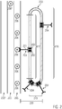
- the diverting device 220 comprises a guide 203. This can be inserted into the" divert-route “areas. 217, "Return Route” 218 and "Resting Position” 219.
- additional route sections such as a repair station for defective diverting segments or another waiting position on which special purpose diverting segments are located, such as but not limited to the discharge of products from the transport route with special properties, or segments that are designed specifically for the cleaning of the transport path 205 or the Ausleittiern 205 'and 205 "or additional carriage 202, is conceivable.
- the inventive embodiment is the use of a linear motor, which of a corresponding guide 203 as a stator, in this embodiment consisting of magnets, and the carriage 202, which then serve as a runner is formed.
- the deflection of the diverter 201 is adjusted by changing the distance of the carriages 202 in the diverting segment 204. If there is an element 206 'to be led out of the quantity of the products 206, the deflection produces a physical contact between the product 206' to be discharged and the lead-out 201.
- the amplitude of the deflection is then changed by regulating the distance of the carriages 202 relative to one another.
- the product 206 to be diverted is conveyed from the transport path 205 to one of the diversion lines 205 'or 205 " Figure 2 is terminated on the lead-out section 205 'and the physical contact between the lead 201 and the discharged product 206 "is terminated by setting the relative distance of the carriages 202 to each other, for example, the initial value 206 on the transport path 205, into the rest position 219.
- the one or more diversion segments 204 can then be stored until the next diversion becomes necessary.
- Figure 3 shows with a possible arrangement of two guides 303, as an assembly of the two carriages 302 of a diverting segment 304 can take place.
- the two guides are arranged so that the surfaces respectively enclosed by the guides are parallel to one another. If these surfaces represent planes, they are plane-parallel.
- One of the carriages 302 is located on the upper guide 303, the other carriages 302 on the lower guide 303. Via suitable connections, the carriages are connected to the outfeed 301 which controls the discharge of products 306 'to be diverted from the transport path 305 to a discharge path 305'. performs.
- the change in the relative position of the carriages 302 to each other in this embodiment is not caused by a different shape of the two guides 303, but by a change in the velocity profile of the carriages along the guides.
- Figure 4 shows a schematic three-dimensional view of the device and a transport path 405 and a discharge path 405 '.
- the carriages 402 may be within the diverting segment 404.
- the deflection of the diverter 401 can then be changed, thus causing the discharge of a product 406 'to be diverted.
- a possible embodiment of the drive of the diverting segments 404 can take place via the use of linear motors, formed by the slides 402 and the parallel guides 403.
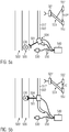
- connection between the proximity switch 530, control device 540 and guide 503 and the carriage 502 in the diverting segment 504 can be realized via wireless connections or cables.
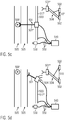
- the distance 510 of the carriages 502 is changed to the distance 510 'by adjusting the speed of the carriages 502 by the controller 540.
- the entire diversion segment 504 and the product 506 'to be diverted now move in the transport direction with the same speed component.
- a discharge of product discourse mandatden 506 ' is carried out on a discharge path 505'.
- the discharge of the product 506 'to be discharged, controlled by the control device 540, can take place so that, depending on the container diameter of the product 506' to be diverted, the discharge is always centered on a discharge path 505 'with the product 506' to be diverted from the mass. dependent, necessary force is performed.
- the speed of the carriages 502 is varied in the direction of movement of the products of the transport path.
- the speed of the diverting segment 504, or of the diverter 501, in the direction of the movement of the products on the transport path 505 remains the same as the speed of the product to be diverted in the transport path. If the exit is completed at the end of the exit route 517 ", the distance between the carriages of 510" is brought back to the initial value 510 ( Figure 5d ). As a result, the deflection of the deflector 501 "is also brought to the initial value Figure 2 shown, return to the rest position 219 via the return path 218 and is available for the next diversion.
- Figure 6 shows some possible embodiments for the mechanical connection of the carriages 602 to the arrester 601.
- the arrester 601 may be connected to the two carriages 602 via rigid connecting rods with hinges 609. It is about the connection of the The diverter 601 with one of the carriages 602 via two connecting rods with hinges prevents uncontrolled movement of the diverter 601.
- the connection of one of the connecting rods via a further hinged connecting rod to the second carriage 602 realizes the change of the deflection with a sure changing distance of the carriages 602 from each other.
- a scissor lever 609 ' This is attached to the carriage 602 via joints.
- the scissor lever is mounted in one place with a hinge and at the other location movable, such as in a recess, a lever end guide or a rail, so that the scissors lever 609 'as such can vary in length flexibly, depending on the relative position of the carriages 602 to each other. Again, the position of the diverter remains constant with respect to the center 611 of the carriages.
- Another possible form of implementation of the mechanical connection of the carriages 602 to the outfeed 601 can be achieved by means of non-rigid connecting elements.
- One possible embodiment is a flexible chain 609 ", for example a push chain in a chain guide, so that the transmission of tensile and shear forces is possible.” This chain 609 "is transferred from one of the carriages 602 via a diverter wheel in the other carriage 602 to the diverter 601 attached.
- the arrester is fastened to the last-mentioned carriage 602 by means of a rail 610 movable on the transport path 505 perpendicular to the direction of movement of the products 506 ', then the change in the distance of the carriages 602 from one another via the chain 609 "directly into a change in the deflection of the diverter 601. In this case, the position of the diverter remains constant with respect to an arbitrarily distinguished axis 611 which moves along with the rail 610.
- Figure 7 shows two possible embodiments of a velocity profile of the carriages 602. Shown is only the velocity profile depending on the location x of the carriages 502 on the diverting path, as shown for example in FIG Figure 2 is shown.
- the first embodiment which may be realized, for example, in an embodiment of the mechanical connection by non-rigid connecting elements, one of the slides moves with constant speed 712.
- the position of the diverter remains constant with respect to this slide, or an excellent point moved by this slide, in the direction of movement of the products in the conveyor line.
- the second carriage experiences an acceleration at a certain location x ', so that its speed 713 is increased.
- the distance 510 of the carriages 502 to each other initially changes to the distance 510 ', and the deflector 501 can perform the discharge of the product 506' to be discharged.
- the speed 713 is also reduced to the speed 712 to maintain the distance 510 "and therewith the set deflection, and when the diverting operation is completed, the change in the distance 510" of the carriages 502 is reversed by the delay Speed 713 is reduced.
- the speeds 712 and 713 are identical so that the distance of the carriages 602 from each other no longer changes.
- both carriages 502 experience a speed change at a particular location such that one of the carriages at speed 713 'experiences a deceleration and the other at speed 712' experiences an acceleration.
- This velocity profile could be realized using rigid fasteners, with the position of the diverter 501 not changing with respect to the center of the link of the two carriages 502 in the direction of movement of the products in the transport path. If the necessary deflection for the discharge of a product 506 'from a transport path 505 to a discharge path 505' is reached, the speeds 712 'and 713' of the two carriages 502 are also the same again.
- the distance of the carriages from each other is restored to their original value by accelerating the carriage 502 at the speed 713 'and by decelerating the carriage 502 at the speed 712'.
- the diversion is completed and the diversion segment 504 can return to the rest position via the return path.
Landscapes
- Engineering & Computer Science (AREA)
- Mechanical Engineering (AREA)
- Discharge Of Articles From Conveyors (AREA)
- Branching, Merging, And Special Transfer Between Conveyors (AREA)
- Attitude Control For Articles On Conveyors (AREA)
- Special Conveying (AREA)
- Wrapping Of Specific Fragile Articles (AREA)
Claims (13)
- Dispositif destiné à extraire d'un parcours de transport, des produits, notamment des contenants pour substances de remplissage, comme des bouteilles, à l'aide d'un ou de plusieurs segments d'extraction (104), dispositif
dans lequel le ou chaque segment d'extraction (104) comprend un chariot (102) et un extracteur (101), et l'extracteur peut produire, par un débattement, l'extraction du produit,
dans lequel le ou chaque segment d'extraction comprend un deuxième chariot (102),
dans lequel chacun des deux chariots est monté de manière mobile sur une glissière de guidage (103), et l'extracteur (101) et les chariots sont reliés mécaniquement les uns aux autres, de sorte que la distance relative entre les chariots détermine le débattement de l'extracteur,
caractérisé en ce que les chariots (102, 202, 402) et la glissière de guidage (103, 203, 403) réalisent un moteur linéaire. - Dispositif selon la revendication 1,
caractérisé en ce que sont prévus plusieurs segments d'extraction, qui présentent une mobilité de manière indépendante les uns des autres. - Dispositif selon les revendications 1 ou 2,
caractérisé en ce que les deux chariots d'un segment d'extraction présentent un montage sur une seule et même glissière de guidage (103) ou sur des glissières de guidage (403) différentes. - Dispositif selon les revendications 1 à 3,
caractérisé en ce que le ou chaque segment d'extraction (104) comprend une liaison mécanique de l'extracteur et des deux chariots (102), de façon telle que respectivement au moins une tige de liaison rigide soit reliée par l'intermédiaire d'articulations, aussi bien avec l'extracteur qu'avec respectivement l'un des deux chariots. - Dispositif selon les revendications 1 à 4,
caractérisé en ce que le ou chaque segment d'extraction présente une liaison mécanique de l'extracteur (601) et des chariots (602) par l'intermédiaire d'un système de bras extensible à articulations en ciseaux (609'). - Dispositif selon les revendications 1 à 5,
caractérisé en ce que le ou chaque segment d'extraction présente une liaison mécanique de l'extracteur et des deux chariots de façon telle que l'extracteur et les deux chariots soient reliés par des éléments de liaison (609") non rigides, par exemple par une chaine, qui convertissent les variations de la position relative des deux chariots l'un par rapport à l'autre en une variation du débattement de l'extracteur. - Dispositif selon les revendications 1 à 6,
caractérisé en ce que le ou chaque segment d'extraction présente une liaison mécanique de l'extracteur et des deux chariots, de manière telle que :un mouvement de l'extracteur par rapport à l'un des deux chariots n'ait lieu que perpendiculairement à la direction de mouvement de déplacement des produits du parcours de transport,ou un mouvement de l'extracteur par rapport au milieu entre les deux chariots n'ait lieu que perpendiculairement à la direction de mouvement de déplacement des produits du parcours de transport. - Dispositif selon les revendications 1 à 7,
caractérisé en ce que la glissière de guidage (203) présente une géométrie fermée en soi. - Le dispositif selon les revendications 1 à 8,
caractérisé en ce que la glissière de guidage (203) présente :un parcours d'extraction (217), qui est placé le long, de préférence de manière parallèle à la direction de mouvement des produits dans le parcours de transport, et sur lequel peut être effectué, à un endroit quelconque, l'extraction du produit à extraire, par le segment d'extraction (204) ;un parcours de retour (218) sur lequel les chariots sont freinés, et sur lequel le mouvement de déplacement des chariots peut se dérouler à l'encontre du mouvement de déplacement des produits dans le parcours de transport ;une position de repos (219) sur laquelle peuvent être successivement agencés des segments d'extraction. - Dispositif selon les revendications 1 à 9,
caractérisé en ce que :un commutateur de proximité (530) délivre l'ordre pour la préparation d'un segment d'extraction ;un dispositif de commande (540) détermine, à partir de la vitesse du produit à extraire dans le parcours de transport, l'accélération et la vitesse des chariots sur le parcours d'extraction. - Dispositif selon les revendications 1 à 10,
caractérisé en ce qu'un ou plusieurs segments d'extraction présentent :la possibilité d'être déplacés sur le parcours d'extraction (217) avec la même vitesse que les produits dans le parcours de transport. - Procédé pour extraire des produits, notamment des contenants pour substances de remplissage, comme des bouteilles, à l'aide d'un ou de plusieurs segments d'extraction (104), dispositif
dans lequel le ou chaque segment d'extraction comprend un chariot (102) et un extracteur (101), et l'extracteur peut produire, par un débattement, l'extraction du produit, et
dans lequel le débattement de l'extracteur est produit au moyen d'une liaison mécanique, par variation de la position relative d'un deuxième chariot (102) par rapport au premier chariot, les segments d'extraction (104) étant entraînés par des moteurs linéaires. - Procédé selon la revendication 12, caractérisé en ce que l'on a une ou plusieurs des caractéristiques suivantes :l'extraction est produite par des segments d'extraction (104) mobiles indépendamment les uns des autres ;l'extraction d'un produit respectif est produite par exactement un segment d'extraction (104) ;l'extraction s'effectue à partir du parcours de transport sur un ou plusieurs parcours d'extraction ;la mise à disposition d'un ou de plusieurs segments d'extraction est produite par un commutateur de proximité (530) ;la commande du ou des segments d'extraction (104) est produite par un dispositif de commande (540).
Applications Claiming Priority (2)
| Application Number | Priority Date | Filing Date | Title |
|---|---|---|---|
| DE102012201059A DE102012201059A1 (de) | 2012-01-25 | 2012-01-25 | Eine Vorrichtung und ein Verfahren zum Ausleiten von Produkten, insbesondere Füllgutbehältern wie Flaschen |
| PCT/EP2012/077056 WO2013110427A1 (fr) | 2012-01-25 | 2012-12-28 | Dispositif et procédé destinés à retirer des produits, notamment des récipients tels que des bouteilles |
Publications (2)
| Publication Number | Publication Date |
|---|---|
| EP2807097A1 EP2807097A1 (fr) | 2014-12-03 |
| EP2807097B1 true EP2807097B1 (fr) | 2017-02-01 |
Family
ID=47557127
Family Applications (1)
| Application Number | Title | Priority Date | Filing Date |
|---|---|---|---|
| EP12813889.8A Active EP2807097B1 (fr) | 2012-01-25 | 2012-12-28 | Appareil et procédé pour dévier des articles, en particulier des récipients tels que des bouteilles |
Country Status (5)
| Country | Link |
|---|---|
| US (1) | US9045291B2 (fr) |
| EP (1) | EP2807097B1 (fr) |
| CN (1) | CN104066663B (fr) |
| DE (1) | DE102012201059A1 (fr) |
| WO (1) | WO2013110427A1 (fr) |
Cited By (1)
| Publication number | Priority date | Publication date | Assignee | Title |
|---|---|---|---|---|
| WO2024249236A1 (fr) * | 2023-05-31 | 2024-12-05 | General Mills, Inc. | Système de traitement permettant de manipuler des morceaux de produit |
Families Citing this family (45)
| Publication number | Priority date | Publication date | Assignee | Title |
|---|---|---|---|---|
| DE102013218402B4 (de) * | 2013-09-13 | 2024-11-28 | Krones Ag | Vorrichtung und Verfahren zum Durchführen von Sonderfunktionen einer Transporteinrichtung in einer Behälterbehandlungsanlage |
| DE102013218399A1 (de) | 2013-09-13 | 2015-03-19 | Krones Ag | Behälterbehandlungsanlage mit einem Ofen und einer Blasformvorrichtung mit Individual-Antrieb von Trägern für Preforms |
| DE102013218394B4 (de) | 2013-09-13 | 2024-10-24 | Krones Ag | Vorrichtung und Verfahren zur Wartung von Transportelementen in einer Behälterbehandlungsanlage |
| DE102013111933A1 (de) | 2013-10-30 | 2015-04-30 | Krones Ag | Behälterbehandlungsanlage und Verfahren zum Verstellen eines Ventils oder einer Ausleiteinrichtung einer Behälterbehandlungsanlage |
| DE102013223494A1 (de) | 2013-11-18 | 2015-05-21 | Robert Bosch Gmbh | Produktstromüberführungsvorrichtung |
| EP3034442B1 (fr) * | 2014-12-17 | 2017-08-02 | UHLMANN PAC-SYSTEME GmbH & Co. KG | Convoyeur destiné au transport de produits |
| EP3034441B1 (fr) * | 2014-12-17 | 2017-04-19 | UHLMANN PAC-SYSTEME GmbH & Co. KG | Dispositif de transport de produits |
| DE102014226965A1 (de) | 2014-12-23 | 2016-06-23 | Krones Ag | Vorrichtung und Verfahren zur fortlaufenden Inspektion von Behältern |
| CH710556B1 (de) * | 2014-12-23 | 2021-06-15 | Rotzinger Ag | Gruppierungseinrichtung für Produktreihen. |
| FR3032698B1 (fr) * | 2015-02-13 | 2022-10-14 | Sidel Participations | "dispositif de convoyage de recipients comportant un organe de prehension mobile transversalement a la direction de deplacement" |
| DE102015203042A1 (de) | 2015-02-20 | 2016-08-25 | Krones Ag | Vorrichtung und Verfahren zum Verteilen und Gruppieren von Behältern |
| EP3109189B1 (fr) * | 2015-06-25 | 2018-10-31 | Sidel Participations | Dispositif de transfert pour transporter des unités d'emballage |
| FR3038299B1 (fr) * | 2015-06-30 | 2017-08-11 | C E R M E X Constructions Etudes Et Rech De Materiels Pour Lemballage Dexpedition | Dispositif et methode de constitution de lots |
| DE102015116808B3 (de) * | 2015-10-02 | 2017-01-19 | Beckhoff Automation Gmbh | Roboter, XY-Tisch für einen solchen Roboter und lineares Transportsystem |
| ITUB20159535A1 (it) | 2015-12-14 | 2017-06-14 | Makro Labelling Srl | Macchina di convogliamento per contenitori |
| US10324699B2 (en) * | 2015-12-15 | 2019-06-18 | International Business Machines Corporation | Enhanceable cross-domain rules engine for unmatched registry entries filtering |
| CA3035537C (fr) | 2016-09-09 | 2021-07-20 | The Procter & Gamble Company | Systeme et procede de remplissage simultane de recipients de formes et/ou de tailles differentes |
| US10558201B2 (en) | 2016-09-09 | 2020-02-11 | The Procter & Gamble Company | System and method for producing products based upon demand |
| EP3510459B1 (fr) | 2016-09-09 | 2026-04-22 | The Procter & Gamble Company | Système et procédé pour l'acheminement indépendant de véhicules chargés de conteneurs pour créer différents produits finis |
| CN109661352B (zh) | 2016-09-09 | 2021-12-03 | 宝洁公司 | 用于用不同的流体组合物同时填充容器的系统和方法 |
| CN109661366B (zh) | 2016-09-09 | 2022-01-14 | 宝洁公司 | 用于独立地引导载具并且将容器和闭合件递送到单元操作站的系统和方法 |
| MX391753B (es) | 2016-09-09 | 2025-03-19 | Procter & Gamble | Sistema de báscula de pesaje en movimiento y método para cinta transportadora con motor sincrónico lineal. |
| WO2018049119A1 (fr) | 2016-09-09 | 2018-03-15 | The Procter & Gamble Company | Procédés de production simultanée de produits différents sur une seule ligne de production |
| HUE055829T2 (hu) * | 2017-01-02 | 2021-12-28 | Manz Ag | Pozícionálóegység |
| EP3431420A1 (fr) * | 2017-07-20 | 2019-01-23 | Rotzinger AG | Dispositif de groupement pour rangées de produits |
| IT201700100513A1 (it) * | 2017-09-07 | 2019-03-07 | Makro Labelling Srl | Macchina per il convogliamento di contenitori |
| CN108678373B (zh) * | 2018-04-08 | 2019-06-28 | 上海建工集团股份有限公司 | 结构卸载装置及其安装方法、使用方法 |
| DE102018205981A1 (de) * | 2018-04-19 | 2019-10-24 | Krones Ag | Formatteil zum Umlenken von Behältern |
| DE102018111715A1 (de) | 2018-05-16 | 2019-11-21 | Beckhoff Automation Gmbh | Lineares transportsystem und system zur kontaktlosen energie- und datenübertragung |
| DE102018219082A1 (de) * | 2018-11-08 | 2020-05-14 | Krones Ag | Vorrichtung zum Gruppieren von Behältern |
| ES3027759T3 (en) | 2019-07-30 | 2025-06-17 | Anheuser Busch Inbev Sa | Denesting apparatus |
| CN114450227A (zh) | 2019-07-30 | 2022-05-06 | 安海斯-布希英博有限公司 | 包装设备 |
| BR112022001661A2 (pt) | 2019-07-30 | 2022-03-22 | Anheuser Busch Inbev Sa | Aparelho de embalagem para empacotamento de embalagens, método para empacotamento de embalagem e uso do aparelho |
| WO2021019053A1 (fr) | 2019-07-30 | 2021-02-04 | Anheuser-Busch Inbev S.A. | Appareil de saisie et de traitement d'articles |
| CN114845937A (zh) | 2019-07-30 | 2022-08-02 | 安海斯-布希英博有限公司 | 用于二次包装的成形工具 |
| IT201900023040A1 (it) * | 2019-12-05 | 2021-06-05 | Ocme Srl | Unita’ di raggruppamento di contenitori cilindrici e relativo metodo. |
| IT201900023448A1 (it) * | 2019-12-10 | 2021-06-10 | Fameccanica Data Spa | Apparecchio e procedimento per alimentare gruppi di prodotti a una macchina confezionatrice |
| DE102020110795A1 (de) | 2020-04-21 | 2021-10-21 | Beckhoff Automation Gmbh | Anschalteinheit in einem linearen Transportsystem |
| EP3932838A1 (fr) * | 2020-06-29 | 2022-01-05 | Siemens Aktiengesellschaft | Procédé et système de transport permettant de manipuler des marchandises de détail sur une voie de transport |
| WO2022090130A1 (fr) * | 2020-10-29 | 2022-05-05 | Shl Medical Ag | Ensemble outil et système d'utilisation dans un système de rail de guidage de chariot |
| EP4089040A1 (fr) * | 2021-05-11 | 2022-11-16 | Fameccanica.Data S.p.A. | Unité de support adaptatif et système de transfert |
| EP4159649A1 (fr) * | 2021-10-01 | 2023-04-05 | TT Innovation AG | Dispositif de manutention et utilisation d'un dispositif de manutention |
| IT202300001422A1 (it) * | 2023-01-31 | 2024-07-31 | Universal Pack S R L | Metodo e apparato di manipolazione di articoli |
| DE102023108047A1 (de) * | 2023-03-29 | 2024-10-02 | Ampack Gmbh | Behälterzuführvorrichtung zu einem Zuführen von Behältern, Produktionsmaschine mit einer entsprechenden Behälterzuführvorrichtung sowie Verfahren zu einem Zuführen von Behältern |
| DE102023117216A1 (de) | 2023-06-29 | 2025-01-02 | Khs Gmbh | Vorrichtung und ein Verfahren zum Ausleiten von Objekten sowie eine Anlage zum Herstellen und/oder Behandeln von Objekten |
Citations (1)
| Publication number | Priority date | Publication date | Assignee | Title |
|---|---|---|---|---|
| US6575691B1 (en) * | 1998-07-22 | 2003-06-10 | Tokyo Electron Limited | Transfer arm |
Family Cites Families (20)
| Publication number | Priority date | Publication date | Assignee | Title |
|---|---|---|---|---|
| ES390486A1 (es) * | 1971-04-07 | 1974-04-01 | Revuelta Lozano | Sistema para la seleccion y separacion en cadencia de obje-tos. |
| DE2924312C2 (de) * | 1979-06-15 | 1981-10-29 | Conto Control Braschos + Achenbach Kg, 5900 Siegen | Vorrichtung zum Aussortieren von als fehlerhaft erkannten Verpackungseinheiten |
| DE3130308C2 (de) | 1981-07-31 | 1984-11-29 | Stratec GmbH, 7534 Birkenfeld | Vorrichtung zum Ausleiten von fehlerhaften Produkten aus einem Förderband |
| DE4024331C2 (de) * | 1990-07-31 | 1993-10-14 | Centro Kontrollsysteme | Vorrichtung zum Sortieren und Verteilen von einreihig auf einem horizontalen Hauptförderband stehend geförderten Verpackungseinheiten, insbesondere Kunststoffflaschen |
| DE19525482A1 (de) * | 1995-07-13 | 1997-01-16 | Bernold Richerzhagen | Vorrichtung zur Verschiebung und Positionierung eines Objektes in einer Ebene |
| DE19729657A1 (de) * | 1997-07-11 | 1999-01-14 | Asea Brown Boveri | Scherenangetriebener Roboterarm und Portalroboter |
| US5988356A (en) * | 1997-09-08 | 1999-11-23 | United Parcel Service Of America, Inc. | Automated diverter capable of sorting bulky articles |
| DE29716459U1 (de) | 1997-09-12 | 1999-01-21 | Heuft Systemtechnik Gmbh | Vorrichtung zum Ausleiten von Gegenständen, die auf einem Transporteur befördert werden |
| US6068105A (en) * | 1997-09-19 | 2000-05-30 | Mannesmann Dematic Rapistan Corp. | Low impact article diverter assembly |
| NL1010989C2 (nl) | 1999-01-11 | 2000-07-13 | Ebm Techniek Bv | Verdeelinrichting. |
| NL1014063C2 (nl) * | 2000-01-14 | 2001-07-17 | Food Processing Systems | Inrichting voor het bij behoud van voorwaartse transportsnelheid herpositioneren van producten. |
| DE20002411U1 (de) | 2000-02-10 | 2001-06-13 | Horst, Michael, Dipl.-Ing., 34128 Kassel | Vorrichtung zum Ablenken von Gegenständen, insbesondere Behältern, von einer Bewegungsbahn |
| DE10112169B4 (de) * | 2001-03-12 | 2006-08-17 | Felsomat Gmbh & Co. Kg | Verkettetes Fertigungssystem zur Durchführung von Bearbeitungsoperationen an Teilen |
| US6889485B2 (en) * | 2002-02-09 | 2005-05-10 | Meadwestvaco Packaging Systems, Llc | Article grouping mechanism |
| ES2279326T5 (es) * | 2004-07-22 | 2013-04-08 | Telstar Technologies, S.L. | Dispositivo para la carga y descarga de recipiente |
| US7410045B2 (en) * | 2006-03-06 | 2008-08-12 | Meadwestvaco Packaging Systems, Llc | Offset overhead plunger |
| GB0616458D0 (en) | 2006-08-18 | 2006-09-27 | Meadwestvaco Packaging Systems | Metering apparatus with independent tool drive means |
| DE102007022910B4 (de) * | 2007-05-14 | 2020-03-12 | Krones Aktiengesellschaft | Vorrichtung zum Verschieben von Gebinden gegenüber einer Transportbahn |
| DE102009003847B4 (de) * | 2009-04-29 | 2025-07-10 | Krones Aktiengesellschaft | Vorrichtung und Verfahren zum Ausleiten von Objekten von einer sich bewegenden Transporteinrichtung |
| EP3013695B1 (fr) * | 2013-06-28 | 2021-04-14 | Graphic Packaging International, LLC | Système de sélection et de regroupement de produits à mouvement continu et méthode de regroupement de produits utilisant le système |
-
2012
- 2012-01-25 DE DE102012201059A patent/DE102012201059A1/de not_active Withdrawn
- 2012-12-28 US US14/371,647 patent/US9045291B2/en active Active
- 2012-12-28 EP EP12813889.8A patent/EP2807097B1/fr active Active
- 2012-12-28 CN CN201280067903.0A patent/CN104066663B/zh active Active
- 2012-12-28 WO PCT/EP2012/077056 patent/WO2013110427A1/fr not_active Ceased
Patent Citations (1)
| Publication number | Priority date | Publication date | Assignee | Title |
|---|---|---|---|---|
| US6575691B1 (en) * | 1998-07-22 | 2003-06-10 | Tokyo Electron Limited | Transfer arm |
Cited By (1)
| Publication number | Priority date | Publication date | Assignee | Title |
|---|---|---|---|---|
| WO2024249236A1 (fr) * | 2023-05-31 | 2024-12-05 | General Mills, Inc. | Système de traitement permettant de manipuler des morceaux de produit |
Also Published As
| Publication number | Publication date |
|---|---|
| US20150027852A1 (en) | 2015-01-29 |
| CN104066663A (zh) | 2014-09-24 |
| WO2013110427A1 (fr) | 2013-08-01 |
| CN104066663B (zh) | 2016-06-22 |
| US9045291B2 (en) | 2015-06-02 |
| DE102012201059A1 (de) | 2013-07-25 |
| EP2807097A1 (fr) | 2014-12-03 |
Similar Documents
| Publication | Publication Date | Title |
|---|---|---|
| EP2807097A1 (fr) | Dispositif et procédé destinés à retirer des produits, notamment des récipients tels que des bouteilles | |
| EP2634100B1 (fr) | Machine de verrouillage de coques et procédé destiné au transport de coques | |
| EP2792626B1 (fr) | Procédé et dispositif de regroupement | |
| EP2500296B1 (fr) | Dispositif et procédé destinés au groupement de produits en vrac | |
| EP3044136B1 (fr) | Appareil et procédé pour grouper des récipients | |
| EP2511203B1 (fr) | Procédé et dispositif de transport de récipients ou de paquets de récipients | |
| EP2364936B1 (fr) | Dispositif et procédé de répartition d'articles à l'intérieur d'un flux d'articles | |
| EP3597577A1 (fr) | Dispositif et procédé permettant de tamponner des articles | |
| EP3057891B1 (fr) | Dispositif d'écartement pour écarter des récipients | |
| DE202007013933U1 (de) | Vorrichtung zum gruppenweisen Verteilen von Behältern | |
| EP3227210A1 (fr) | Dispositif et procédé d'alignement d'articles et/ou de marchandises rassemblés en des groupes | |
| EP1012087B1 (fr) | Dispositif et procede pour mettre a l'ecart des objets transportes sur un transporteur | |
| DE102010050035A1 (de) | Transportstrecke für einen ungeordneten Massenstrom einer Vielzahl separater Artikel und Verfahren zur Beeinflussung des Massenstroms | |
| EP2945891B1 (fr) | Installation de transport | |
| DE102014202087A1 (de) | Vorrichtung und Verfahren zum Aufteilen eines Stroms stückiger Produkte | |
| EP2254815B1 (fr) | Magasin intermédiaire pour des marchandises de détail | |
| AT516092A1 (de) | Vorrichtung und Verfahren zum Transport von schlauchförmigen Sackkörpern | |
| DE19856649A1 (de) | Verfahren und Einrichtung zum Speichern von Fördergut | |
| DE102017104381A1 (de) | Vorrichtung und Verfahren zum Transportieren und Abteilen von Behältern | |
| DE3130308A1 (de) | Vorrichtung zum ausleiten von fehlerhaften produkten aus einem foerderband | |
| EP0657259A1 (fr) | Dispositif de coupe pour boudin d'argile | |
| EP2295325B1 (fr) | Agencement de plusieurs dispositifs de manipulation reliés ensemble pour des articles et procédé de fonctionnement d'un tel agencement | |
| DE69705184T2 (de) | Einrichtung zum Speichern von Gegenständen auf einer Förderschleife | |
| DE202020102108U1 (de) | Vorrichtung zum Transportieren von Stückgütern mit Verteileinrichtung | |
| WO2019206858A1 (fr) | Dispositif et procédé de transport de colis avec un système d'aiguillage |
Legal Events
| Date | Code | Title | Description |
|---|---|---|---|
| PUAI | Public reference made under article 153(3) epc to a published international application that has entered the european phase |
Free format text: ORIGINAL CODE: 0009012 |
|
| 17P | Request for examination filed |
Effective date: 20140627 |
|
| AK | Designated contracting states |
Kind code of ref document: A1 Designated state(s): AL AT BE BG CH CY CZ DE DK EE ES FI FR GB GR HR HU IE IS IT LI LT LU LV MC MK MT NL NO PL PT RO RS SE SI SK SM TR |
|
| DAX | Request for extension of the european patent (deleted) | ||
| 17Q | First examination report despatched |
Effective date: 20160204 |
|
| GRAP | Despatch of communication of intention to grant a patent |
Free format text: ORIGINAL CODE: EPIDOSNIGR1 |
|
| INTG | Intention to grant announced |
Effective date: 20160810 |
|
| GRAS | Grant fee paid |
Free format text: ORIGINAL CODE: EPIDOSNIGR3 |
|
| GRAA | (expected) grant |
Free format text: ORIGINAL CODE: 0009210 |
|
| AK | Designated contracting states |
Kind code of ref document: B1 Designated state(s): AL AT BE BG CH CY CZ DE DK EE ES FI FR GB GR HR HU IE IS IT LI LT LU LV MC MK MT NL NO PL PT RO RS SE SI SK SM TR |
|
| REG | Reference to a national code |
Ref country code: GB Ref legal event code: FG4D Free format text: NOT ENGLISH |
|
| REG | Reference to a national code |
Ref country code: CH Ref legal event code: EP Ref country code: AT Ref legal event code: REF Ref document number: 865380 Country of ref document: AT Kind code of ref document: T Effective date: 20170215 |
|
| REG | Reference to a national code |
Ref country code: IE Ref legal event code: FG4D Free format text: LANGUAGE OF EP DOCUMENT: GERMAN |
|
| REG | Reference to a national code |
Ref country code: DE Ref legal event code: R096 Ref document number: 502012009480 Country of ref document: DE |
|
| REG | Reference to a national code |
Ref country code: NL Ref legal event code: MP Effective date: 20170201 |
|
| REG | Reference to a national code |
Ref country code: LT Ref legal event code: MG4D |
|
| PG25 | Lapsed in a contracting state [announced via postgrant information from national office to epo] |
Ref country code: NO Free format text: LAPSE BECAUSE OF FAILURE TO SUBMIT A TRANSLATION OF THE DESCRIPTION OR TO PAY THE FEE WITHIN THE PRESCRIBED TIME-LIMIT Effective date: 20170501 Ref country code: GR Free format text: LAPSE BECAUSE OF FAILURE TO SUBMIT A TRANSLATION OF THE DESCRIPTION OR TO PAY THE FEE WITHIN THE PRESCRIBED TIME-LIMIT Effective date: 20170502 Ref country code: HR Free format text: LAPSE BECAUSE OF FAILURE TO SUBMIT A TRANSLATION OF THE DESCRIPTION OR TO PAY THE FEE WITHIN THE PRESCRIBED TIME-LIMIT Effective date: 20170201 Ref country code: FI Free format text: LAPSE BECAUSE OF FAILURE TO SUBMIT A TRANSLATION OF THE DESCRIPTION OR TO PAY THE FEE WITHIN THE PRESCRIBED TIME-LIMIT Effective date: 20170201 Ref country code: LT Free format text: LAPSE BECAUSE OF FAILURE TO SUBMIT A TRANSLATION OF THE DESCRIPTION OR TO PAY THE FEE WITHIN THE PRESCRIBED TIME-LIMIT Effective date: 20170201 Ref country code: IS Free format text: LAPSE BECAUSE OF FAILURE TO SUBMIT A TRANSLATION OF THE DESCRIPTION OR TO PAY THE FEE WITHIN THE PRESCRIBED TIME-LIMIT Effective date: 20170601 |
|
| PG25 | Lapsed in a contracting state [announced via postgrant information from national office to epo] |
Ref country code: ES Free format text: LAPSE BECAUSE OF FAILURE TO SUBMIT A TRANSLATION OF THE DESCRIPTION OR TO PAY THE FEE WITHIN THE PRESCRIBED TIME-LIMIT Effective date: 20170201 Ref country code: BG Free format text: LAPSE BECAUSE OF FAILURE TO SUBMIT A TRANSLATION OF THE DESCRIPTION OR TO PAY THE FEE WITHIN THE PRESCRIBED TIME-LIMIT Effective date: 20170501 Ref country code: RS Free format text: LAPSE BECAUSE OF FAILURE TO SUBMIT A TRANSLATION OF THE DESCRIPTION OR TO PAY THE FEE WITHIN THE PRESCRIBED TIME-LIMIT Effective date: 20170201 Ref country code: PT Free format text: LAPSE BECAUSE OF FAILURE TO SUBMIT A TRANSLATION OF THE DESCRIPTION OR TO PAY THE FEE WITHIN THE PRESCRIBED TIME-LIMIT Effective date: 20170601 Ref country code: LV Free format text: LAPSE BECAUSE OF FAILURE TO SUBMIT A TRANSLATION OF THE DESCRIPTION OR TO PAY THE FEE WITHIN THE PRESCRIBED TIME-LIMIT Effective date: 20170201 Ref country code: PL Free format text: LAPSE BECAUSE OF FAILURE TO SUBMIT A TRANSLATION OF THE DESCRIPTION OR TO PAY THE FEE WITHIN THE PRESCRIBED TIME-LIMIT Effective date: 20170201 Ref country code: NL Free format text: LAPSE BECAUSE OF FAILURE TO SUBMIT A TRANSLATION OF THE DESCRIPTION OR TO PAY THE FEE WITHIN THE PRESCRIBED TIME-LIMIT Effective date: 20170201 Ref country code: SE Free format text: LAPSE BECAUSE OF FAILURE TO SUBMIT A TRANSLATION OF THE DESCRIPTION OR TO PAY THE FEE WITHIN THE PRESCRIBED TIME-LIMIT Effective date: 20170201 |
|
| PG25 | Lapsed in a contracting state [announced via postgrant information from national office to epo] |
Ref country code: EE Free format text: LAPSE BECAUSE OF FAILURE TO SUBMIT A TRANSLATION OF THE DESCRIPTION OR TO PAY THE FEE WITHIN THE PRESCRIBED TIME-LIMIT Effective date: 20170201 Ref country code: RO Free format text: LAPSE BECAUSE OF FAILURE TO SUBMIT A TRANSLATION OF THE DESCRIPTION OR TO PAY THE FEE WITHIN THE PRESCRIBED TIME-LIMIT Effective date: 20170201 Ref country code: SK Free format text: LAPSE BECAUSE OF FAILURE TO SUBMIT A TRANSLATION OF THE DESCRIPTION OR TO PAY THE FEE WITHIN THE PRESCRIBED TIME-LIMIT Effective date: 20170201 Ref country code: CZ Free format text: LAPSE BECAUSE OF FAILURE TO SUBMIT A TRANSLATION OF THE DESCRIPTION OR TO PAY THE FEE WITHIN THE PRESCRIBED TIME-LIMIT Effective date: 20170201 |
|
| REG | Reference to a national code |
Ref country code: DE Ref legal event code: R097 Ref document number: 502012009480 Country of ref document: DE |
|
| REG | Reference to a national code |
Ref country code: FR Ref legal event code: PLFP Year of fee payment: 6 |
|
| PG25 | Lapsed in a contracting state [announced via postgrant information from national office to epo] |
Ref country code: SM Free format text: LAPSE BECAUSE OF FAILURE TO SUBMIT A TRANSLATION OF THE DESCRIPTION OR TO PAY THE FEE WITHIN THE PRESCRIBED TIME-LIMIT Effective date: 20170201 Ref country code: DK Free format text: LAPSE BECAUSE OF FAILURE TO SUBMIT A TRANSLATION OF THE DESCRIPTION OR TO PAY THE FEE WITHIN THE PRESCRIBED TIME-LIMIT Effective date: 20170201 |
|
| PLBE | No opposition filed within time limit |
Free format text: ORIGINAL CODE: 0009261 |
|
| STAA | Information on the status of an ep patent application or granted ep patent |
Free format text: STATUS: NO OPPOSITION FILED WITHIN TIME LIMIT |
|
| 26N | No opposition filed |
Effective date: 20171103 |
|
| PG25 | Lapsed in a contracting state [announced via postgrant information from national office to epo] |
Ref country code: SI Free format text: LAPSE BECAUSE OF FAILURE TO SUBMIT A TRANSLATION OF THE DESCRIPTION OR TO PAY THE FEE WITHIN THE PRESCRIBED TIME-LIMIT Effective date: 20170201 |
|
| REG | Reference to a national code |
Ref country code: CH Ref legal event code: PL |
|
| REG | Reference to a national code |
Ref country code: IE Ref legal event code: MM4A |
|
| PG25 | Lapsed in a contracting state [announced via postgrant information from national office to epo] |
Ref country code: LU Free format text: LAPSE BECAUSE OF NON-PAYMENT OF DUE FEES Effective date: 20171228 Ref country code: MT Free format text: LAPSE BECAUSE OF FAILURE TO SUBMIT A TRANSLATION OF THE DESCRIPTION OR TO PAY THE FEE WITHIN THE PRESCRIBED TIME-LIMIT Effective date: 20170201 |
|
| REG | Reference to a national code |
Ref country code: BE Ref legal event code: MM Effective date: 20171231 |
|
| PG25 | Lapsed in a contracting state [announced via postgrant information from national office to epo] |
Ref country code: IE Free format text: LAPSE BECAUSE OF NON-PAYMENT OF DUE FEES Effective date: 20171228 |
|
| PG25 | Lapsed in a contracting state [announced via postgrant information from national office to epo] |
Ref country code: CH Free format text: LAPSE BECAUSE OF NON-PAYMENT OF DUE FEES Effective date: 20171231 Ref country code: LI Free format text: LAPSE BECAUSE OF NON-PAYMENT OF DUE FEES Effective date: 20171231 Ref country code: BE Free format text: LAPSE BECAUSE OF NON-PAYMENT OF DUE FEES Effective date: 20171231 |
|
| REG | Reference to a national code |
Ref country code: AT Ref legal event code: MM01 Ref document number: 865380 Country of ref document: AT Kind code of ref document: T Effective date: 20171228 |
|
| PG25 | Lapsed in a contracting state [announced via postgrant information from national office to epo] |
Ref country code: AT Free format text: LAPSE BECAUSE OF NON-PAYMENT OF DUE FEES Effective date: 20171228 |
|
| PG25 | Lapsed in a contracting state [announced via postgrant information from national office to epo] |
Ref country code: HU Free format text: LAPSE BECAUSE OF FAILURE TO SUBMIT A TRANSLATION OF THE DESCRIPTION OR TO PAY THE FEE WITHIN THE PRESCRIBED TIME-LIMIT; INVALID AB INITIO Effective date: 20121228 Ref country code: MC Free format text: LAPSE BECAUSE OF FAILURE TO SUBMIT A TRANSLATION OF THE DESCRIPTION OR TO PAY THE FEE WITHIN THE PRESCRIBED TIME-LIMIT Effective date: 20170201 |
|
| PG25 | Lapsed in a contracting state [announced via postgrant information from national office to epo] |
Ref country code: CY Free format text: LAPSE BECAUSE OF FAILURE TO SUBMIT A TRANSLATION OF THE DESCRIPTION OR TO PAY THE FEE WITHIN THE PRESCRIBED TIME-LIMIT Effective date: 20170201 |
|
| PG25 | Lapsed in a contracting state [announced via postgrant information from national office to epo] |
Ref country code: MK Free format text: LAPSE BECAUSE OF FAILURE TO SUBMIT A TRANSLATION OF THE DESCRIPTION OR TO PAY THE FEE WITHIN THE PRESCRIBED TIME-LIMIT Effective date: 20170201 |
|
| PG25 | Lapsed in a contracting state [announced via postgrant information from national office to epo] |
Ref country code: TR Free format text: LAPSE BECAUSE OF FAILURE TO SUBMIT A TRANSLATION OF THE DESCRIPTION OR TO PAY THE FEE WITHIN THE PRESCRIBED TIME-LIMIT Effective date: 20170201 |
|
| PG25 | Lapsed in a contracting state [announced via postgrant information from national office to epo] |
Ref country code: AL Free format text: LAPSE BECAUSE OF FAILURE TO SUBMIT A TRANSLATION OF THE DESCRIPTION OR TO PAY THE FEE WITHIN THE PRESCRIBED TIME-LIMIT Effective date: 20170201 |
|
| PGFP | Annual fee paid to national office [announced via postgrant information from national office to epo] |
Ref country code: GB Payment date: 20231109 Year of fee payment: 12 |
|
| GBPC | Gb: european patent ceased through non-payment of renewal fee |
Effective date: 20241228 |
|
| PG25 | Lapsed in a contracting state [announced via postgrant information from national office to epo] |
Ref country code: GB Free format text: LAPSE BECAUSE OF NON-PAYMENT OF DUE FEES Effective date: 20241228 |
|
| PGFP | Annual fee paid to national office [announced via postgrant information from national office to epo] |
Ref country code: DE Payment date: 20251104 Year of fee payment: 14 |
|
| PGFP | Annual fee paid to national office [announced via postgrant information from national office to epo] |
Ref country code: IT Payment date: 20251121 Year of fee payment: 14 |
|
| PGFP | Annual fee paid to national office [announced via postgrant information from national office to epo] |
Ref country code: FR Payment date: 20251110 Year of fee payment: 14 |