EP2807357B1 - Wärmetauscher - Google Patents
Wärmetauscher Download PDFInfo
- Publication number
- EP2807357B1 EP2807357B1 EP13741305.0A EP13741305A EP2807357B1 EP 2807357 B1 EP2807357 B1 EP 2807357B1 EP 13741305 A EP13741305 A EP 13741305A EP 2807357 B1 EP2807357 B1 EP 2807357B1
- Authority
- EP
- European Patent Office
- Prior art keywords
- air
- heat exchanger
- gas turbine
- turbine engine
- fins
- Prior art date
- Legal status (The legal status is an assumption and is not a legal conclusion. Google has not performed a legal analysis and makes no representation as to the accuracy of the status listed.)
- Active
Links
Images
Classifications
-
- F—MECHANICAL ENGINEERING; LIGHTING; HEATING; WEAPONS; BLASTING
- F02—COMBUSTION ENGINES; HOT-GAS OR COMBUSTION-PRODUCT ENGINE PLANTS
- F02C—GAS-TURBINE PLANTS; AIR INTAKES FOR JET-PROPULSION PLANTS; CONTROLLING FUEL SUPPLY IN AIR-BREATHING JET-PROPULSION PLANTS
- F02C6/00—Plural gas-turbine plants; Combinations of gas-turbine plants with other apparatus; Adaptations of gas-turbine plants for special use
- F02C6/04—Gas-turbine plants providing heated or pressurised working fluid for other apparatus, e.g. without mechanical power output
- F02C6/06—Gas-turbine plants providing heated or pressurised working fluid for other apparatus, e.g. without mechanical power output providing compressed gas
- F02C6/08—Gas-turbine plants providing heated or pressurised working fluid for other apparatus, e.g. without mechanical power output providing compressed gas the gas being bled from the gas-turbine compressor
-
- F—MECHANICAL ENGINEERING; LIGHTING; HEATING; WEAPONS; BLASTING
- F02—COMBUSTION ENGINES; HOT-GAS OR COMBUSTION-PRODUCT ENGINE PLANTS
- F02C—GAS-TURBINE PLANTS; AIR INTAKES FOR JET-PROPULSION PLANTS; CONTROLLING FUEL SUPPLY IN AIR-BREATHING JET-PROPULSION PLANTS
- F02C7/00—Features, components parts, details or accessories, not provided for in, or of interest apart form groups F02C1/00 - F02C6/00; Air intakes for jet-propulsion plants
- F02C7/12—Cooling of plants
- F02C7/16—Cooling of plants characterised by cooling medium
- F02C7/18—Cooling of plants characterised by cooling medium the medium being gaseous, e.g. air
- F02C7/185—Cooling means for reducing the temperature of the cooling air or gas
-
- F—MECHANICAL ENGINEERING; LIGHTING; HEATING; WEAPONS; BLASTING
- F02—COMBUSTION ENGINES; HOT-GAS OR COMBUSTION-PRODUCT ENGINE PLANTS
- F02K—JET-PROPULSION PLANTS
- F02K3/00—Plants including a gas turbine driving a compressor or a ducted fan
- F02K3/08—Plants including a gas turbine driving a compressor or a ducted fan with supplementary heating of the working fluid; Control thereof
- F02K3/105—Heating the by-pass flow
- F02K3/115—Heating the by-pass flow by means of indirect heat exchange
-
- F—MECHANICAL ENGINEERING; LIGHTING; HEATING; WEAPONS; BLASTING
- F02—COMBUSTION ENGINES; HOT-GAS OR COMBUSTION-PRODUCT ENGINE PLANTS
- F02C—GAS-TURBINE PLANTS; AIR INTAKES FOR JET-PROPULSION PLANTS; CONTROLLING FUEL SUPPLY IN AIR-BREATHING JET-PROPULSION PLANTS
- F02C6/00—Plural gas-turbine plants; Combinations of gas-turbine plants with other apparatus; Adaptations of gas-turbine plants for special use
- F02C6/04—Gas-turbine plants providing heated or pressurised working fluid for other apparatus, e.g. without mechanical power output
- F02C6/06—Gas-turbine plants providing heated or pressurised working fluid for other apparatus, e.g. without mechanical power output providing compressed gas
-
- F—MECHANICAL ENGINEERING; LIGHTING; HEATING; WEAPONS; BLASTING
- F02—COMBUSTION ENGINES; HOT-GAS OR COMBUSTION-PRODUCT ENGINE PLANTS
- F02C—GAS-TURBINE PLANTS; AIR INTAKES FOR JET-PROPULSION PLANTS; CONTROLLING FUEL SUPPLY IN AIR-BREATHING JET-PROPULSION PLANTS
- F02C7/00—Features, components parts, details or accessories, not provided for in, or of interest apart form groups F02C1/00 - F02C6/00; Air intakes for jet-propulsion plants
- F02C7/12—Cooling of plants
- F02C7/16—Cooling of plants characterised by cooling medium
-
- F—MECHANICAL ENGINEERING; LIGHTING; HEATING; WEAPONS; BLASTING
- F05—INDEXING SCHEMES RELATING TO ENGINES OR PUMPS IN VARIOUS SUBCLASSES OF CLASSES F01-F04
- F05D—INDEXING SCHEME FOR ASPECTS RELATING TO NON-POSITIVE-DISPLACEMENT MACHINES OR ENGINES, GAS-TURBINES OR JET-PROPULSION PLANTS
- F05D2260/00—Function
- F05D2260/20—Heat transfer, e.g. cooling
-
- Y—GENERAL TAGGING OF NEW TECHNOLOGICAL DEVELOPMENTS; GENERAL TAGGING OF CROSS-SECTIONAL TECHNOLOGIES SPANNING OVER SEVERAL SECTIONS OF THE IPC; TECHNICAL SUBJECTS COVERED BY FORMER USPC CROSS-REFERENCE ART COLLECTIONS [XRACs] AND DIGESTS
- Y02—TECHNOLOGIES OR APPLICATIONS FOR MITIGATION OR ADAPTATION AGAINST CLIMATE CHANGE
- Y02T—CLIMATE CHANGE MITIGATION TECHNOLOGIES RELATED TO TRANSPORTATION
- Y02T50/00—Aeronautics or air transport
- Y02T50/60—Efficient propulsion technologies, e.g. for aircraft
Definitions
- This application relates to a cooler for use in a gas turbine engine.
- Gas turbine engines typically include a fan delivering air into a compressor. The air is compressed and passed into a combustion section. From the combustion section, the air is mixed with fuel and ignited, and then passes over turbine rotors.
- a number of accessories are associated with gas turbine engines.
- a generator generates electricity.
- Various fluid supply systems such as oil supply, fuel supply, etc. deliver fluids around the gas turbine engine.
- Many of these accessories require some degree of cooling and may receive lubricant, which also requires cooling.
- heat exchangers there are a number of heat exchangers in a gas turbine engine.
- a heat exchanger may be placed in a bypass air duct, such that cooling air being driven by the fan will pass across the heat exchanger.
- heat exchangers have been placed in other locations where air may be driven through the gas turbine engine.
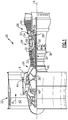
- FIG. 1 schematically illustrates a gas turbine engine 20.
- the gas turbine engine 20 is disclosed herein as a two-spool turbofan that generally incorporates a fan section 22, a compressor section 24, a combustor section 26 and a turbine section 28.
- Alternative engines might include an augmentor section (not shown) among other systems or features.
- the fan section 22 drives air along a bypass flowpath while the compressor section 24 drives air along a core flowpath for compression and communication into the combustor section 26 then expansion through the turbine section 28.
- FIG. 1 schematically illustrates a gas turbine engine 20.
- the gas turbine engine 20 is disclosed herein as a two-spool turbofan that generally incorporates a fan section 22, a compressor section 24, a combustor section 26 and a turbine section 28.
- Alternative engines might include an augmentor section (not shown) among other systems or features.
- the fan section 22 drives air along a bypass flowpath while the compressor section 24 drives air along a core flowpath for compression and communication into the combustor section 26
- the engine 20 generally includes a low speed spool 30 and a high speed spool 32 mounted for rotation about an engine central longitudinal axis A relative to an engine static structure 36 via several bearing systems 38. It should be understood that various bearing systems 38 at various locations may alternatively or additionally be provided.
- the low speed spool 30 generally includes an inner shaft 40 that interconnects a fan 42, a low pressure compressor 44 and a low pressure turbine 46.
- the inner shaft 40 is connected to the fan 42 through a geared architecture 48 to drive the fan 42 at a lower speed than the low speed spool 30.
- the high speed spool 32 includes an outer shaft 50 that interconnects a high pressure compressor 52 and high pressure turbine 54.
- a combustor 56 is arranged between the high pressure compressor 52 and the high pressure turbine 54.
- a mid-turbine frame 57 of the engine static structure 36 is arranged generally between the high pressure turbine 54 and the low pressure turbine 46.
- the mid-turbine frame 57 further supports bearing systems 38 in the turbine section 28.
- the inner shaft 40 and the outer shaft 50 are concentric and rotate via bearing systems 38 about the engine central longitudinal axis A which is collinear with their longitudinal axes.
- the core airflow is compressed by the low pressure compressor 44 then the high pressure compressor 52, mixed and burned with fuel in the combustor 56, then expanded over the high pressure turbine 54 and low pressure turbine 46.
- the mid-turbine frame 57 includes airfoils 59 which are in the core airflow path.
- the turbines 46, 54 rotationally drive the respective low speed spool 30 and high speed spool 32 in response to the expansion.
- the engine 20 in one example is a high-bypass geared aircraft engine.
- the engine 20 bypass ratio is greater than about six (6:1), with an example embodiment being greater than a ratio of approximately ten (10:1)
- the geared architecture 48 is an epicyclic gear train, such as a planetary gear system or other gear system, with a gear reduction ratio of greater than about 2.3:1
- the low pressure turbine 46 has a pressure ratio that is greater than about five (5:1).
- the engine 20 bypass ratio is greater than about 10:1
- the fan diameter is significantly larger than that of the low pressure compressor 44
- the low pressure turbine 46 has a pressure ratio that is greater than about five (5:1).
- Low pressure turbine 46 pressure ratio is pressure measured prior to inlet of low pressure turbine 46 as related to the pressure at the outlet of the low pressure turbine 46 prior to an exhaust nozzle.
- the geared architecture 48 may be an epicycle gear train, such as a planetary gear system or other gear system, with a gear reduction ratio of greater than about 2.5:1. It should be understood, however, that the above parameters are only exemplary of one embodiment of a geared architecture engine is applicable to other gas turbine engines including direct drive turbofans.
- the fan section 22 of the engine 20 is designed for a particular flight condition -- typically cruise at about 0.8 Mach and about 35,000 feet (10,668 m).
- the flight condition of 0.8 Mach and 35,000 ft (10,668 m), with the engine at its best fuel consumption - also known as "bucket cruise Thrust Specific Fuel Consumption ('TSFC')" - is the industry standard parameter of lbm of fuel being burned divided by lbf of thrust the engine produces at that minimum point.
- TSFC thrust specific fuel consumption
- Low fan pressure ratio is the pressure ratio across the fan blade alone, without a Fan Exit Guide Vane (“FEGV”) system.
- the low fan pressure ratio as disclosed herein according to one non-limiting embodiment is less than about 1.45.
- Low corrected fan tip speed is the actual fan tip speed in ft/sec divided by an industry standard temperature correction of [(Tambient deg R) / 518.7) ⁇ 0.5].
- the "Low corrected fan tip speed” as disclosed herein according to one non-limiting embodiment is less than about 1150 ft / second (350.5 m/s).
- This application relates to a heat exchanger in such a gas turbine engine which utilizes cooling air from two distinct sources such that the heat exchanger may be made smaller than the prior art.
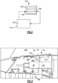
- Figure 2 shows a circuit for cooling oil such as may be associated with an accessory 152.
- accessory 152 may be a generator.
- Hot oil leaves the generator 152 after cooling the generator, and enters an inlet 156 associated with a heat exchanger 154.
- the oil passes through a series of passages 155 from the inlet manifold, to an outlet manifold, and then the outlet 158 of the heat exchanger. This oil is then returned to the generator 152, having been cooled by air.
- FIG 3 shows a location for the heat exchanger 154.
- the location may be approximately at area X as shown in Figure 1 .
- the heat exchanger 154 is located such that one side has convective cooling features 160 that are disposed at least partially within the duct 100 that is in fluid communication with bypass airflow B (see Fig. 1 ).
- the convective cooling features 160 may be fins, pins, projections, ribs, etc.
- the features 160 provide surface area for convective cooling. These features 160 may be relatively small, as they will extend into the bypass air flow, and it may be desirable to limit obstruction to this flow.
- the size and geometry of the features 160 may be optimized to consider both the weight of the heat exchanger, drag within the bypass air flow, and convective cooling magnitude.
- the opposed side of the heat exchanger 154 has features 162 which tend are disposed at least partially within a bleed air supply chamber 200.
- bleed air is air downstream of a compressor rotor 164 (which may be part of the low pressure compressor 44, see Figure 1 ) that is diverted out of the core engine flow and into the chamber 200.
- This typically occurs at low power conditions, and serve to reduce the load of downstream compressor stages, and the rest of the engine by not driving unnecessary air through the engine. This may occur while the aircraft is idling on the ground, as an example.
- the heat exchanger 154 is located such that the features 162 are in fluid communication with the bleed air flow.
- the size and geometry of the features 162 may be optimized to consider both the weight of the heat exchanger, drag within the bleed air flow, and convective cooling magnitude. These low pressure conditions are also coincidentally a most challenging time for the heat exchanger 154 to be adequately cooled by the bypass air alone in duct 100. As an example, there may be a limited amount of bypass air under those conditions. In the past, the heat exchangers cooled by bypass air have been necessarily unduly large, as they must still adequately cool the fluid even under the low power conditions.
- the features 160 extend away from a surface of the heat exchanger 154 for a lesser distance than the features 162 extend away from the opposed surface. This is because the features 160 extend into the bypass air flow, and as mentioned above, it would be desirable to limit their height.
- the features 160 may extend for a greater distance along a flow path of the bypass air B than do the features 162. This is generally as illustrated in Figure 3 .
- the features 160 extend away from a surface of the heat exchanger for .40" (1.02 cm), and extend along the path of the bypass air flow B for 6" (15.2 cm). In this same embodiment, the features 162 extend away from the surface for .5" (1.27 cm), and extend along the flow path for 4" (10.2 cm).
- a mechanism 68 can selectively close off the passage 166 and block further bleed air flow.
- mechanisms include valves and gates that may be mechanically and/or electromechanically controlled. This occurs as the engine moves more toward full power operation. However, under those conditions, the bypass airflow will be greatly increased in volume, and should adequately cool the fluid in the heat exchanger 154 on its own.
Landscapes
- Engineering & Computer Science (AREA)
- Chemical & Material Sciences (AREA)
- Combustion & Propulsion (AREA)
- Mechanical Engineering (AREA)
- General Engineering & Computer Science (AREA)
- Structures Of Non-Positive Displacement Pumps (AREA)
Claims (7)
- Gasturbinentriebwerk (20), das Folgendes umfasst:ein Gebläse (42), einen Verdichterabschnitt (24), eine Brennkammer (56) und einen Turbinenabschnitt (28), wobei das Gebläse (42) einen Teil der Luft in den Verdichterabschnitt (24) und einen Teil der Luft als Bypass-Luft (B) in eine Leitung liefert;ein Zapfluftsystem zum Entlüften einer Menge an Luft aus dem Verdichterabschnitt (24) in eine Kammer (200), wobei das Zapfluftsystem eine Öffnung aufweist, die selektiv geschlossen werden kann, um Zapfluft zu blockieren, oder geöffnet werden kann, um einen Entlüftungsstrom von dem Verdichterabschnitt (24) zu der Kammer (200) zu ermöglichen; undeinen Wärmetauscher (154), der zu kühlende, Fluid enthaltende Durchlässe (155) aufweist, wobei der Wärmetauscher (154) derart positioniert ist, dass eine erste Fläche des Wärmetauschers (154) durch Bypass-Luft (B) in der Leitung berührt wird, und eine zweite Fläche des Wärmetauschers (154) durch Zapfluft berührt wird, wenn das Zapfluftsystem Luft von dem Verdichterabschnitt (24) in die Kammer (200) leitet, sodass die Bypass-Luft (B) und die Zapfluft Fluid in den Durchlässen (155) kühlen.
- Gasturbinentriebwerk (20) nach Anspruch 1, wobei Rippen (160) auf der ersten Fläche des Wärmetauschers (154) gebildet werden, die sich in den Bypass-Luftstrom (B) erstrecken.
- Gasturbinentriebwerk (20) nach Anspruch 2, wobei Rippen (162) auch auf der zweiten Fläche des Wärmetauschers (154) gebildet werden und sich in Richtung des Zapfluftstroms erstrecken.
- Gasturbinentriebwerk (20) nach Anspruch 3, wobei die Rippen (162) auf der zweiten Fläche sich für eine höhere Höhe von den Fluid enthaltenden Durchlässen (155) weg erstrecken als es die Rippen (160) auf der ersten Fläche tun.
- Gasturbinentriebwerk (20) nach Anspruch 3 oder 4, wobei die Rippen (160) auf der ersten Fläche sich für eine längere Länge entlang eines Strömungswegs der Bypass-Luft (B) erstrecken als es die Rippen (162) auf der zweiten Fläche tun.
- Gasturbinentriebwerk (20) nach einem der vorhergehenden Ansprüche, wobei der Wärmetauscher (154) selektiv ein einer Zusatzvorrichtung (152) des Gasturbinentriebwerks (20) zugeordnetes Fluid kühlt.
- Gasturbinentriebwerk (20) nach Anspruch 6, wobei die Zusatzvorrichtung (152) ein Generator ist.
Applications Claiming Priority (2)
| Application Number | Priority Date | Filing Date | Title |
|---|---|---|---|
| US13/360,745 US9267434B2 (en) | 2012-01-29 | 2012-01-29 | Heat exchanger |
| PCT/US2013/023577 WO2013113038A1 (en) | 2012-01-29 | 2013-01-29 | Heat exchanger |
Publications (3)
| Publication Number | Publication Date |
|---|---|
| EP2807357A1 EP2807357A1 (de) | 2014-12-03 |
| EP2807357A4 EP2807357A4 (de) | 2015-10-07 |
| EP2807357B1 true EP2807357B1 (de) | 2018-12-05 |
Family
ID=48869063
Family Applications (1)
| Application Number | Title | Priority Date | Filing Date |
|---|---|---|---|
| EP13741305.0A Active EP2807357B1 (de) | 2012-01-29 | 2013-01-29 | Wärmetauscher |
Country Status (3)
| Country | Link |
|---|---|
| US (1) | US9267434B2 (de) |
| EP (1) | EP2807357B1 (de) |
| WO (1) | WO2013113038A1 (de) |
Families Citing this family (10)
| Publication number | Priority date | Publication date | Assignee | Title |
|---|---|---|---|---|
| EP3094845B1 (de) * | 2014-01-15 | 2020-04-29 | United Technologies Corporation | Kühlsysteme für gasturbinenmotoren |
| US10443429B2 (en) | 2014-02-13 | 2019-10-15 | United Technologies Corporation | Gas turbine nacelle ventilation manifold having a circumferential varying cross-sectional area |
| EP3108130B1 (de) * | 2014-02-19 | 2018-12-12 | United Technologies Corporation | Gasturbinenmotor mit mindestkühlluftstrom |
| EP2930314B1 (de) * | 2014-04-08 | 2022-06-08 | Rolls-Royce Corporation | Generator mit gesteuertem luftkühlungsverstärker |
| US9341119B2 (en) | 2014-07-03 | 2016-05-17 | Hamilton Sundstrand Corporation | Cooling air system for aircraft turbine engine |
| US11035626B2 (en) | 2018-09-10 | 2021-06-15 | Hamilton Sunstrand Corporation | Heat exchanger with enhanced end sheet heat transfer |
| US11512639B2 (en) * | 2021-01-26 | 2022-11-29 | General Electric Company | Heat transfer system |
| US12584455B2 (en) | 2022-08-02 | 2026-03-24 | General Electric Company | Airflow mixer assembly for a gas turbine engine |
| US12253027B2 (en) * | 2022-11-14 | 2025-03-18 | Pratt & Whitney Canada Corp. | Lubricant reservoir with integrated heat exchanger |
| US12553392B2 (en) | 2024-06-18 | 2026-02-17 | Rtx Corporation | Gas turbine engine with thermal management |
Family Cites Families (30)
| Publication number | Priority date | Publication date | Assignee | Title |
|---|---|---|---|---|
| US4254618A (en) * | 1977-08-18 | 1981-03-10 | General Electric Company | Cooling air cooler for a gas turbofan engine |
| US4474001A (en) * | 1981-04-01 | 1984-10-02 | United Technologies Corporation | Cooling system for the electrical generator of a turbofan gas turbine engine |
| US4546605A (en) * | 1983-12-16 | 1985-10-15 | United Technologies Corporation | Heat exchange system |
| US5048288A (en) * | 1988-12-20 | 1991-09-17 | United Technologies Corporation | Combined turbine stator cooling and turbine tip clearance control |
| US5269133A (en) | 1991-06-18 | 1993-12-14 | General Electric Company | Heat exchanger for cooling a gas turbine |
| US5269135A (en) * | 1991-10-28 | 1993-12-14 | General Electric Company | Gas turbine engine fan cooled heat exchanger |
| US5261228A (en) * | 1992-06-25 | 1993-11-16 | General Electric Company | Apparatus for bleeding air |
| FR2695161B1 (fr) * | 1992-08-26 | 1994-11-04 | Snecma | Système de refroidissement d'un compresseur de turbomachine et de contrôle des jeux. |
| US6058696A (en) * | 1997-12-22 | 2000-05-09 | United Technologies Corporation | Inlet and outlet module for a heat exchanger for a flowpath for working medium gases |
| US6584778B1 (en) | 2000-05-11 | 2003-07-01 | General Electric Co. | Methods and apparatus for supplying cooling air to turbine engines |
| FR2864996B1 (fr) | 2004-01-13 | 2006-03-10 | Snecma Moteurs | Systeme de refroidissement de parties chaudes d'un moteur d'aeronef, et moteur d'aeronef equipe d'un tel systeme de refroidissement |
| US7454894B2 (en) * | 2004-12-07 | 2008-11-25 | United Technologies Corporation | Supplemental oil cooler airflow for gas turbine engine |
| FR2891313A1 (fr) | 2005-09-26 | 2007-03-30 | Airbus France Sas | Turbomoteur a double flux pourvu d'un prerefroidisseur |
| US7607308B2 (en) | 2005-12-08 | 2009-10-27 | General Electric Company | Shrouded turbofan bleed duct |
| US7694505B2 (en) | 2006-07-31 | 2010-04-13 | General Electric Company | Gas turbine engine assembly and method of assembling same |
| US20080053060A1 (en) | 2006-08-29 | 2008-03-06 | Pratt & Whitney Canada Corp. | Bypass lip seal |
| WO2008045054A1 (en) | 2006-10-12 | 2008-04-17 | United Technologies Corporation | Modulating flow through gas turbine engine cooling system |
| US8387362B2 (en) * | 2006-10-19 | 2013-03-05 | Michael Ralph Storage | Method and apparatus for operating gas turbine engine heat exchangers |
| US7862293B2 (en) | 2007-05-03 | 2011-01-04 | Pratt & Whitney Canada Corp. | Low profile bleed air cooler |
| US7966831B2 (en) | 2007-08-28 | 2011-06-28 | General Electric Company | Apparatus and method for suppressing dynamic pressure instability in bleed duct |
| US8181443B2 (en) * | 2008-12-10 | 2012-05-22 | Pratt & Whitney Canada Corp. | Heat exchanger to cool turbine air cooling flow |
| FR2946089B1 (fr) * | 2009-05-27 | 2012-05-04 | Airbus France | Dispositif de refroidissement de fluides pour propulseur a turbomachine |
| US8307662B2 (en) | 2009-10-15 | 2012-11-13 | General Electric Company | Gas turbine engine temperature modulated cooling flow |
| EP2339123B1 (de) * | 2009-12-23 | 2013-07-10 | Techspace Aero S.A. | Innere Seite des Mantels des Sekundärstromes eines Turbostrahltriebwerkes und Verfahren zur Montage eines solchen Mantels |
| US8910465B2 (en) | 2009-12-31 | 2014-12-16 | Rolls-Royce North American Technologies, Inc. | Gas turbine engine and heat exchange system |
| GB201007063D0 (en) * | 2010-04-28 | 2010-06-09 | Rolls Royce Plc | A gas turbine engine |
| US8784047B2 (en) * | 2010-11-04 | 2014-07-22 | Hamilton Sundstrand Corporation | Gas turbine engine heat exchanger with tapered fins |
| US9051943B2 (en) * | 2010-11-04 | 2015-06-09 | Hamilton Sundstrand Corporation | Gas turbine engine heat exchanger fins with periodic gaps |
| US8904753B2 (en) * | 2011-04-28 | 2014-12-09 | United Technologies Corporation | Thermal management system for gas turbine engine |
| US9045998B2 (en) * | 2011-12-12 | 2015-06-02 | Honeywell International Inc. | System for directing air flow to a plurality of plena |
-
2012
- 2012-01-29 US US13/360,745 patent/US9267434B2/en not_active Expired - Fee Related
-
2013
- 2013-01-29 WO PCT/US2013/023577 patent/WO2013113038A1/en not_active Ceased
- 2013-01-29 EP EP13741305.0A patent/EP2807357B1/de active Active
Non-Patent Citations (1)
| Title |
|---|
| None * |
Also Published As
| Publication number | Publication date |
|---|---|
| WO2013113038A1 (en) | 2013-08-01 |
| EP2807357A1 (de) | 2014-12-03 |
| US9267434B2 (en) | 2016-02-23 |
| EP2807357A4 (de) | 2015-10-07 |
| US20130192254A1 (en) | 2013-08-01 |
Similar Documents
| Publication | Publication Date | Title |
|---|---|---|
| EP2807357B1 (de) | Wärmetauscher | |
| EP3296543B1 (de) | Gasturbinenmotor mit zwischengekühlter kühlluft und turbinenantrieb | |
| EP3330524B1 (de) | An der rückseite eines gasturbinentriebwerks montierter wärmetauscher für anspruchsvolle temperaturanwendungen | |
| EP3126640B1 (de) | Aktive spielraumsteuerung für einen gasturbinenmotor | |
| EP3239493B1 (de) | Einfacher wärmetauscher mit superlegierungsmaterialien | |
| EP3369911A1 (de) | Hitzeschild für gasturbinenmotordiffusorgehäuse | |
| EP3060760A1 (de) | Schaufel mit aussenkernkühlung | |
| EP2906806B1 (de) | Turbogebläsemotor mit optimierter diffusorgehäuseflanschposition | |
| EP3543505B1 (de) | Zwischengekühlte kühlluft mit kombinierten merkmalen | |
| EP3330515B1 (de) | Gasturbinenmotor | |
| EP3219959B1 (de) | Gekühlte zapf-kühlluft mit verwendung eines bestehenden wärmetauschers | |
| EP3572645B1 (de) | Verbesserte nachgeschaltete turbinenschaufelkühlung für einen gasturbinenmotor | |
| EP3296548B1 (de) | In einem zwischengehäuse montierten wärmetauscher für gasturbinenmotor | |
| EP3388637B1 (de) | Kühlluftkammer für äussere schaufelluftdichtung | |
| EP3388625B1 (de) | Gekühlte kühlluft zur schaufelaussenluftabdichtung durch eine statorschaufel | |
| EP3358152B1 (de) | Externe mischkammer für einen gasturbinenmotor mit gekühlter turbinenkühlluft | |
| EP3181869B1 (de) | Verdichterkerninnendurchmesserkühlung | |
| EP3348812B1 (de) | Kühlluft eines gekühlten turbinentriebwerks mit kaltluftabführung | |
| EP3179034B1 (de) | Turbinenkühlluft mit mehreren quellen |
Legal Events
| Date | Code | Title | Description |
|---|---|---|---|
| PUAI | Public reference made under article 153(3) epc to a published international application that has entered the european phase |
Free format text: ORIGINAL CODE: 0009012 |
|
| 17P | Request for examination filed |
Effective date: 20140818 |
|
| AK | Designated contracting states |
Kind code of ref document: A1 Designated state(s): AL AT BE BG CH CY CZ DE DK EE ES FI FR GB GR HR HU IE IS IT LI LT LU LV MC MK MT NL NO PL PT RO RS SE SI SK SM TR |
|
| DAX | Request for extension of the european patent (deleted) | ||
| RA4 | Supplementary search report drawn up and despatched (corrected) |
Effective date: 20150908 |
|
| RIC1 | Information provided on ipc code assigned before grant |
Ipc: F01D 25/12 20060101ALI20150902BHEP Ipc: F02K 3/115 20060101AFI20150902BHEP Ipc: F02C 6/08 20060101ALI20150902BHEP Ipc: F02C 7/18 20060101ALI20150902BHEP |
|
| RAP1 | Party data changed (applicant data changed or rights of an application transferred) |
Owner name: UNITED TECHNOLOGIES CORPORATION |
|
| REG | Reference to a national code |
Ref country code: DE Ref legal event code: R079 Ref document number: 602013047777 Country of ref document: DE Free format text: PREVIOUS MAIN CLASS: F02C0007140000 Ipc: F02K0003115000 |
|
| GRAP | Despatch of communication of intention to grant a patent |
Free format text: ORIGINAL CODE: EPIDOSNIGR1 |
|
| STAA | Information on the status of an ep patent application or granted ep patent |
Free format text: STATUS: GRANT OF PATENT IS INTENDED |
|
| RIC1 | Information provided on ipc code assigned before grant |
Ipc: F02K 3/115 20060101AFI20180517BHEP Ipc: F02C 6/08 20060101ALI20180517BHEP Ipc: F02C 7/18 20060101ALI20180517BHEP Ipc: F01D 25/12 20060101ALI20180517BHEP |
|
| INTG | Intention to grant announced |
Effective date: 20180614 |
|
| GRAS | Grant fee paid |
Free format text: ORIGINAL CODE: EPIDOSNIGR3 |
|
| GRAA | (expected) grant |
Free format text: ORIGINAL CODE: 0009210 |
|
| STAA | Information on the status of an ep patent application or granted ep patent |
Free format text: STATUS: THE PATENT HAS BEEN GRANTED |
|
| AK | Designated contracting states |
Kind code of ref document: B1 Designated state(s): AL AT BE BG CH CY CZ DE DK EE ES FI FR GB GR HR HU IE IS IT LI LT LU LV MC MK MT NL NO PL PT RO RS SE SI SK SM TR |
|
| REG | Reference to a national code |
Ref country code: GB Ref legal event code: FG4D |
|
| REG | Reference to a national code |
Ref country code: CH Ref legal event code: EP |
|
| REG | Reference to a national code |
Ref country code: AT Ref legal event code: REF Ref document number: 1073387 Country of ref document: AT Kind code of ref document: T Effective date: 20181215 |
|
| REG | Reference to a national code |
Ref country code: IE Ref legal event code: FG4D |
|
| REG | Reference to a national code |
Ref country code: DE Ref legal event code: R096 Ref document number: 602013047777 Country of ref document: DE |
|
| REG | Reference to a national code |
Ref country code: NL Ref legal event code: MP Effective date: 20181205 |
|
| REG | Reference to a national code |
Ref country code: AT Ref legal event code: MK05 Ref document number: 1073387 Country of ref document: AT Kind code of ref document: T Effective date: 20181205 |
|
| REG | Reference to a national code |
Ref country code: LT Ref legal event code: MG4D |
|
| PG25 | Lapsed in a contracting state [announced via postgrant information from national office to epo] |
Ref country code: FI Free format text: LAPSE BECAUSE OF FAILURE TO SUBMIT A TRANSLATION OF THE DESCRIPTION OR TO PAY THE FEE WITHIN THE PRESCRIBED TIME-LIMIT Effective date: 20181205 Ref country code: LT Free format text: LAPSE BECAUSE OF FAILURE TO SUBMIT A TRANSLATION OF THE DESCRIPTION OR TO PAY THE FEE WITHIN THE PRESCRIBED TIME-LIMIT Effective date: 20181205 Ref country code: BG Free format text: LAPSE BECAUSE OF FAILURE TO SUBMIT A TRANSLATION OF THE DESCRIPTION OR TO PAY THE FEE WITHIN THE PRESCRIBED TIME-LIMIT Effective date: 20190305 Ref country code: HR Free format text: LAPSE BECAUSE OF FAILURE TO SUBMIT A TRANSLATION OF THE DESCRIPTION OR TO PAY THE FEE WITHIN THE PRESCRIBED TIME-LIMIT Effective date: 20181205 Ref country code: ES Free format text: LAPSE BECAUSE OF FAILURE TO SUBMIT A TRANSLATION OF THE DESCRIPTION OR TO PAY THE FEE WITHIN THE PRESCRIBED TIME-LIMIT Effective date: 20181205 Ref country code: LV Free format text: LAPSE BECAUSE OF FAILURE TO SUBMIT A TRANSLATION OF THE DESCRIPTION OR TO PAY THE FEE WITHIN THE PRESCRIBED TIME-LIMIT Effective date: 20181205 Ref country code: NO Free format text: LAPSE BECAUSE OF FAILURE TO SUBMIT A TRANSLATION OF THE DESCRIPTION OR TO PAY THE FEE WITHIN THE PRESCRIBED TIME-LIMIT Effective date: 20190305 Ref country code: AT Free format text: LAPSE BECAUSE OF FAILURE TO SUBMIT A TRANSLATION OF THE DESCRIPTION OR TO PAY THE FEE WITHIN THE PRESCRIBED TIME-LIMIT Effective date: 20181205 |
|
| PG25 | Lapsed in a contracting state [announced via postgrant information from national office to epo] |
Ref country code: AL Free format text: LAPSE BECAUSE OF FAILURE TO SUBMIT A TRANSLATION OF THE DESCRIPTION OR TO PAY THE FEE WITHIN THE PRESCRIBED TIME-LIMIT Effective date: 20181205 Ref country code: RS Free format text: LAPSE BECAUSE OF FAILURE TO SUBMIT A TRANSLATION OF THE DESCRIPTION OR TO PAY THE FEE WITHIN THE PRESCRIBED TIME-LIMIT Effective date: 20181205 Ref country code: GR Free format text: LAPSE BECAUSE OF FAILURE TO SUBMIT A TRANSLATION OF THE DESCRIPTION OR TO PAY THE FEE WITHIN THE PRESCRIBED TIME-LIMIT Effective date: 20190306 Ref country code: SE Free format text: LAPSE BECAUSE OF FAILURE TO SUBMIT A TRANSLATION OF THE DESCRIPTION OR TO PAY THE FEE WITHIN THE PRESCRIBED TIME-LIMIT Effective date: 20181205 |
|
| PG25 | Lapsed in a contracting state [announced via postgrant information from national office to epo] |
Ref country code: NL Free format text: LAPSE BECAUSE OF FAILURE TO SUBMIT A TRANSLATION OF THE DESCRIPTION OR TO PAY THE FEE WITHIN THE PRESCRIBED TIME-LIMIT Effective date: 20181205 |
|
| PG25 | Lapsed in a contracting state [announced via postgrant information from national office to epo] |
Ref country code: IT Free format text: LAPSE BECAUSE OF FAILURE TO SUBMIT A TRANSLATION OF THE DESCRIPTION OR TO PAY THE FEE WITHIN THE PRESCRIBED TIME-LIMIT Effective date: 20181205 Ref country code: CZ Free format text: LAPSE BECAUSE OF FAILURE TO SUBMIT A TRANSLATION OF THE DESCRIPTION OR TO PAY THE FEE WITHIN THE PRESCRIBED TIME-LIMIT Effective date: 20181205 Ref country code: PT Free format text: LAPSE BECAUSE OF FAILURE TO SUBMIT A TRANSLATION OF THE DESCRIPTION OR TO PAY THE FEE WITHIN THE PRESCRIBED TIME-LIMIT Effective date: 20190405 Ref country code: PL Free format text: LAPSE BECAUSE OF FAILURE TO SUBMIT A TRANSLATION OF THE DESCRIPTION OR TO PAY THE FEE WITHIN THE PRESCRIBED TIME-LIMIT Effective date: 20181205 |
|
| PG25 | Lapsed in a contracting state [announced via postgrant information from national office to epo] |
Ref country code: SK Free format text: LAPSE BECAUSE OF FAILURE TO SUBMIT A TRANSLATION OF THE DESCRIPTION OR TO PAY THE FEE WITHIN THE PRESCRIBED TIME-LIMIT Effective date: 20181205 Ref country code: RO Free format text: LAPSE BECAUSE OF FAILURE TO SUBMIT A TRANSLATION OF THE DESCRIPTION OR TO PAY THE FEE WITHIN THE PRESCRIBED TIME-LIMIT Effective date: 20181205 Ref country code: IS Free format text: LAPSE BECAUSE OF FAILURE TO SUBMIT A TRANSLATION OF THE DESCRIPTION OR TO PAY THE FEE WITHIN THE PRESCRIBED TIME-LIMIT Effective date: 20190405 Ref country code: SM Free format text: LAPSE BECAUSE OF FAILURE TO SUBMIT A TRANSLATION OF THE DESCRIPTION OR TO PAY THE FEE WITHIN THE PRESCRIBED TIME-LIMIT Effective date: 20181205 Ref country code: EE Free format text: LAPSE BECAUSE OF FAILURE TO SUBMIT A TRANSLATION OF THE DESCRIPTION OR TO PAY THE FEE WITHIN THE PRESCRIBED TIME-LIMIT Effective date: 20181205 |
|
| REG | Reference to a national code |
Ref country code: CH Ref legal event code: PL |
|
| REG | Reference to a national code |
Ref country code: DE Ref legal event code: R097 Ref document number: 602013047777 Country of ref document: DE |
|
| PG25 | Lapsed in a contracting state [announced via postgrant information from national office to epo] |
Ref country code: LU Free format text: LAPSE BECAUSE OF NON-PAYMENT OF DUE FEES Effective date: 20190129 |
|
| PLBE | No opposition filed within time limit |
Free format text: ORIGINAL CODE: 0009261 |
|
| STAA | Information on the status of an ep patent application or granted ep patent |
Free format text: STATUS: NO OPPOSITION FILED WITHIN TIME LIMIT |
|
| REG | Reference to a national code |
Ref country code: BE Ref legal event code: MM Effective date: 20190131 |
|
| REG | Reference to a national code |
Ref country code: IE Ref legal event code: MM4A |
|
| PG25 | Lapsed in a contracting state [announced via postgrant information from national office to epo] |
Ref country code: DK Free format text: LAPSE BECAUSE OF FAILURE TO SUBMIT A TRANSLATION OF THE DESCRIPTION OR TO PAY THE FEE WITHIN THE PRESCRIBED TIME-LIMIT Effective date: 20181205 Ref country code: SI Free format text: LAPSE BECAUSE OF FAILURE TO SUBMIT A TRANSLATION OF THE DESCRIPTION OR TO PAY THE FEE WITHIN THE PRESCRIBED TIME-LIMIT Effective date: 20181205 Ref country code: MC Free format text: LAPSE BECAUSE OF FAILURE TO SUBMIT A TRANSLATION OF THE DESCRIPTION OR TO PAY THE FEE WITHIN THE PRESCRIBED TIME-LIMIT Effective date: 20181205 |
|
| 26N | No opposition filed |
Effective date: 20190906 |
|
| PG25 | Lapsed in a contracting state [announced via postgrant information from national office to epo] |
Ref country code: BE Free format text: LAPSE BECAUSE OF NON-PAYMENT OF DUE FEES Effective date: 20190131 |
|
| PG25 | Lapsed in a contracting state [announced via postgrant information from national office to epo] |
Ref country code: LI Free format text: LAPSE BECAUSE OF NON-PAYMENT OF DUE FEES Effective date: 20190131 Ref country code: CH Free format text: LAPSE BECAUSE OF NON-PAYMENT OF DUE FEES Effective date: 20190131 |
|
| PG25 | Lapsed in a contracting state [announced via postgrant information from national office to epo] |
Ref country code: IE Free format text: LAPSE BECAUSE OF NON-PAYMENT OF DUE FEES Effective date: 20190129 |
|
| PG25 | Lapsed in a contracting state [announced via postgrant information from national office to epo] |
Ref country code: TR Free format text: LAPSE BECAUSE OF FAILURE TO SUBMIT A TRANSLATION OF THE DESCRIPTION OR TO PAY THE FEE WITHIN THE PRESCRIBED TIME-LIMIT Effective date: 20181205 |
|
| PG25 | Lapsed in a contracting state [announced via postgrant information from national office to epo] |
Ref country code: MT Free format text: LAPSE BECAUSE OF NON-PAYMENT OF DUE FEES Effective date: 20190129 |
|
| PG25 | Lapsed in a contracting state [announced via postgrant information from national office to epo] |
Ref country code: CY Free format text: LAPSE BECAUSE OF FAILURE TO SUBMIT A TRANSLATION OF THE DESCRIPTION OR TO PAY THE FEE WITHIN THE PRESCRIBED TIME-LIMIT Effective date: 20181205 |
|
| PG25 | Lapsed in a contracting state [announced via postgrant information from national office to epo] |
Ref country code: HU Free format text: LAPSE BECAUSE OF FAILURE TO SUBMIT A TRANSLATION OF THE DESCRIPTION OR TO PAY THE FEE WITHIN THE PRESCRIBED TIME-LIMIT; INVALID AB INITIO Effective date: 20130129 |
|
| PG25 | Lapsed in a contracting state [announced via postgrant information from national office to epo] |
Ref country code: MK Free format text: LAPSE BECAUSE OF FAILURE TO SUBMIT A TRANSLATION OF THE DESCRIPTION OR TO PAY THE FEE WITHIN THE PRESCRIBED TIME-LIMIT Effective date: 20181205 |
|
| REG | Reference to a national code |
Ref country code: DE Ref legal event code: R081 Ref document number: 602013047777 Country of ref document: DE Owner name: RAYTHEON TECHNOLOGIES CORPORATION (N.D.GES.D.S, US Free format text: FORMER OWNER: UNITED TECHNOLOGIES CORPORATION, FARMINGTON, CONN., US Ref country code: DE Ref legal event code: R081 Ref document number: 602013047777 Country of ref document: DE Owner name: RTX CORPORATION (N.D.GES.D. STAATES DELAWARE),, US Free format text: FORMER OWNER: UNITED TECHNOLOGIES CORPORATION, FARMINGTON, CONN., US |
|
| P01 | Opt-out of the competence of the unified patent court (upc) registered |
Effective date: 20230520 |
|
| REG | Reference to a national code |
Ref country code: DE Ref legal event code: R081 Ref document number: 602013047777 Country of ref document: DE Owner name: RTX CORPORATION (N.D.GES.D. STAATES DELAWARE),, US Free format text: FORMER OWNER: RAYTHEON TECHNOLOGIES CORPORATION (N.D.GES.D.STAATES DELAWARE), ARLINGTON, VA, US |
|
| PGFP | Annual fee paid to national office [announced via postgrant information from national office to epo] |
Ref country code: GB Payment date: 20251220 Year of fee payment: 14 |
|
| PGFP | Annual fee paid to national office [announced via postgrant information from national office to epo] |
Ref country code: FR Payment date: 20251217 Year of fee payment: 14 |
|
| PGFP | Annual fee paid to national office [announced via postgrant information from national office to epo] |
Ref country code: DE Payment date: 20251217 Year of fee payment: 14 |