EP2807368B1 - Ventilblock für einen hochdruckspeicher eines common-rail schweröl-einspritzsystems - Google Patents
Ventilblock für einen hochdruckspeicher eines common-rail schweröl-einspritzsystems Download PDFInfo
- Publication number
- EP2807368B1 EP2807368B1 EP13714683.3A EP13714683A EP2807368B1 EP 2807368 B1 EP2807368 B1 EP 2807368B1 EP 13714683 A EP13714683 A EP 13714683A EP 2807368 B1 EP2807368 B1 EP 2807368B1
- Authority
- EP
- European Patent Office
- Prior art keywords
- pressure
- valve
- valve block
- fuel
- low
- Prior art date
- Legal status (The legal status is an assumption and is not a legal conclusion. Google has not performed a legal analysis and makes no representation as to the accuracy of the status listed.)
- Active
Links
Images
Classifications
-
- F—MECHANICAL ENGINEERING; LIGHTING; HEATING; WEAPONS; BLASTING
- F02—COMBUSTION ENGINES; HOT-GAS OR COMBUSTION-PRODUCT ENGINE PLANTS
- F02M—SUPPLYING COMBUSTION ENGINES IN GENERAL WITH COMBUSTIBLE MIXTURES OR CONSTITUENTS THEREOF
- F02M63/00—Other fuel-injection apparatus having pertinent characteristics not provided for in groups F02M39/00 - F02M57/00 or F02M67/00; Details, component parts, or accessories of fuel-injection apparatus, not provided for in, or of interest apart from, the apparatus of groups F02M39/00 - F02M61/00 or F02M67/00; Combination of fuel pump with other devices, e.g. lubricating oil pump
- F02M63/02—Fuel-injection apparatus having several injectors fed by a common pumping element, or having several pumping elements feeding a common injector; Fuel-injection apparatus having provisions for cutting-out pumps, pumping elements, or injectors; Fuel-injection apparatus having provisions for variably interconnecting pumping elements and injectors alternatively
- F02M63/0225—Fuel-injection apparatus having a common rail feeding several injectors ; Means for varying pressure in common rails; Pumps feeding common rails
- F02M63/023—Means for varying pressure in common rails
- F02M63/0235—Means for varying pressure in common rails by bleeding fuel pressure
- F02M63/025—Means for varying pressure in common rails by bleeding fuel pressure from the common rail
-
- F—MECHANICAL ENGINEERING; LIGHTING; HEATING; WEAPONS; BLASTING
- F02—COMBUSTION ENGINES; HOT-GAS OR COMBUSTION-PRODUCT ENGINE PLANTS
- F02M—SUPPLYING COMBUSTION ENGINES IN GENERAL WITH COMBUSTIBLE MIXTURES OR CONSTITUENTS THEREOF
- F02M63/00—Other fuel-injection apparatus having pertinent characteristics not provided for in groups F02M39/00 - F02M57/00 or F02M67/00; Details, component parts, or accessories of fuel-injection apparatus, not provided for in, or of interest apart from, the apparatus of groups F02M39/00 - F02M61/00 or F02M67/00; Combination of fuel pump with other devices, e.g. lubricating oil pump
- F02M63/0012—Valves
- F02M63/0031—Valves characterized by the type of valves, e.g. special valve member details, valve seat details, valve housing details
- F02M63/005—Pressure relief valves
-
- F—MECHANICAL ENGINEERING; LIGHTING; HEATING; WEAPONS; BLASTING
- F02—COMBUSTION ENGINES; HOT-GAS OR COMBUSTION-PRODUCT ENGINE PLANTS
- F02M—SUPPLYING COMBUSTION ENGINES IN GENERAL WITH COMBUSTIBLE MIXTURES OR CONSTITUENTS THEREOF
- F02M63/00—Other fuel-injection apparatus having pertinent characteristics not provided for in groups F02M39/00 - F02M57/00 or F02M67/00; Details, component parts, or accessories of fuel-injection apparatus, not provided for in, or of interest apart from, the apparatus of groups F02M39/00 - F02M61/00 or F02M67/00; Combination of fuel pump with other devices, e.g. lubricating oil pump
- F02M63/02—Fuel-injection apparatus having several injectors fed by a common pumping element, or having several pumping elements feeding a common injector; Fuel-injection apparatus having provisions for cutting-out pumps, pumping elements, or injectors; Fuel-injection apparatus having provisions for variably interconnecting pumping elements and injectors alternatively
- F02M63/0205—Fuel-injection apparatus having several injectors fed by a common pumping element, or having several pumping elements feeding a common injector; Fuel-injection apparatus having provisions for cutting-out pumps, pumping elements, or injectors; Fuel-injection apparatus having provisions for variably interconnecting pumping elements and injectors alternatively for cutting-out pumps or injectors in case of abnormal operation of the engine or the injection apparatus, e.g. over-speed, break-down of fuel pumps or injectors ; for cutting-out pumps for stopping the engine
- F02M63/0215—Fuel-injection apparatus having several injectors fed by a common pumping element, or having several pumping elements feeding a common injector; Fuel-injection apparatus having provisions for cutting-out pumps, pumping elements, or injectors; Fuel-injection apparatus having provisions for variably interconnecting pumping elements and injectors alternatively for cutting-out pumps or injectors in case of abnormal operation of the engine or the injection apparatus, e.g. over-speed, break-down of fuel pumps or injectors ; for cutting-out pumps for stopping the engine by draining or closing fuel conduits
Definitions
- the invention relates to a valve block for a high pressure accumulator of a common rail heavy oil injection system for internal combustion engines with a pressure relief valve, wherein the pressure relief valve is received with its high pressure port side in the valve block and the valve block has a leakage return.
- the invention further relates to a pressure relief valve for installation in a valve block having a high-pressure connection having a high-pressure port side, which is provided for receiving in the valve block.
- Pressure relief valves serve to limit the pressure in the high-pressure accumulator (rail) of a common-rail heavy-oil injection system while at the same time providing an emergency driving feature.
- the pressure relief valve is usually screwed into a valve block on the rail and communicates with a spring-loaded valve pin via a sealing seat with the highly compressed fuel in contact. On the back of the sealing seat, the valve is connected via a line to the low-pressure return of the common-rail system. If the rail pressure moves within the permissible range, the valve remains closed by the applied spring force and is sealed against the return line. If the maximum permissible rail pressure is exceeded in the event of a fault, the valve opens and limits the system pressure.
- a pressure relief valve is for example in the WO 2004/083695 A1 or in the EP 1 314 883 A described.
- low-quality fuels such as heavy oil are used in very large diesel engines, especially in marine diesel engines. Due to the special physical properties of heavy oils special precautions must be taken for operation. For example, the viscosity of heavy fuel oil is much higher than normal diesel fuel, so heating to more than 80 ° C is required to pump the heavy oil at all.
- the high viscosity of heavy fuel oil means that fuel must always be circulated in the piping system during engine standstill in order to prevent the formation of heavy oil in the pipes.
- a purge valve is provided in common-rail heavy fuel injection systems, which is closed during operation of the engine while the high-pressure side parts of the fuel system and thus the rail against a low-pressure side fuel return line through which fuel can be returned to the tank, closes. At standstill of the engine, this purge valve can now be opened, so that fuel from the high pressure side through the high pressure lines and the rail through the valve to the low pressure side and in the sequence in the tank is circulated, the fuel held by a preheater at a corresponding temperature so that solidification of the heavy oil in the pipes is prevented.
- the purge valve In addition to the possibility of generating a circulation flow for controlling the temperature of the fuel in the system, the purge valve also has the function of an emergency stop valve. By suitable control of the purge valve, the system pressure can be lowered very quickly in an emergency, without the injection injectors themselves must be disabled.
- the pressure limiting valve and the flushing valve are accommodated with their high-pressure connection side in a valve block arranged on the rail.
- the amount of fuel discharged from the rail is generally discharged into the fuel return via a discharge line arranged on the side of the pressure-limiting valve opposite the high-pressure connection side.
- the pressure limiting valve and the additional valves which may be provided must each have their own return line, which means a design effort in terms of the piping and is disadvantageous in terms of assembly and handling.
- the present invention therefore aims to avoid the mentioned disadvantages.
- valve of the type mentioned is inventively further developed such that a low pressure port of the pressure relief valve is connected to the valve block and connected to the leakage return.
- a low pressure port of the pressure relief valve is connected to the valve block and connected to the leakage return.
- the low pressure port on the high pressure port side of the pressure relief valve opens into the valve block, ie on the side with which the pressure relief valve is accommodated in the valve block.
- the invention makes it possible for a plurality of valves, which are accommodated in a valve block of a high-pressure accumulator, to share a common return line on the low-pressure side.
- the merging of the individual low-pressure side processes is preferably carried out in the valve block, so that in fact only a single return line must be connected to the valve block.
- the valve block is equipped with at least one further valve, namely a flushing valve, which is accommodated with its high-pressure connection side in the valve block.
- a pressure relief valve which is suitable for installation in a valve block and which has a high-pressure connection having high-pressure port side, which is provided for receiving in the valve block, a low pressure drain of the pressure relief valve opens at the high pressure port side ,
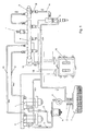
- FIG.1 a common rail heavy fuel injection system
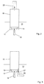
- Fig.2 a schematic view of a valve block with a pressure relief valve according to the prior art
- Fig. 3 a schematic view of a valve block with a pressure relief valve according to the invention
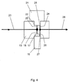
- Fig. 4 a schematic view of a valve block according to the invention with a pressure relief valve and a purge valve.
- Fig. 1 is a common rail heavy fuel injection system shown schematically. From the tank 1 is fed by a prefeed pump 3 fuel, which was heated in the preheater 2 via a fuel filter 4 and fuel lines 11 at least one high pressure pump 5, in which the fuel is compressed to system pressures of higher than 1400 bar.
- the compressed fuel passes through high pressure lines 12 in at least one rail 6, which is equipped, inter alia, with at least one valve block 13 and a rail pressure sensor 7.
- the valve block 13 includes a pressure relief valve and a purge valve.
- the pressure in the rail 6 is set by the control unit 10 by regulating the amount of fuel delivered by the high-pressure pump 5 into the high-pressure line 12.
- the fuel passes via a flow restrictor 9 via the high-pressure line 14 into the injection injector 8, which is likewise controlled by the control unit 10.
- the fuel control amount required for the function of the injection injector 8 passes back into the tank 1 via the low-pressure return line 15.
- a low-pressure return line 15 leads from the valve block 13 to the tank 1, so that a subset of the fuel can be diverted directly into the tank 1.
- a pressure relief valve 16 is received with its high pressure port side 17.
- the high-pressure inlet 18 of Pressure limiting valve 16 is closed by a spring-loaded in the closing direction valve closure member 19.
- the pressure of the high-pressure accumulator via the high-pressure inlet 18 is at.
- the valve closing member 19 is displaced inwardly against the spring force, so that fuel can escape from the high pressure accumulator.
- the diverted fuel quantity leaves the pressure relief valve 16 via the low-pressure outlet 20 and is via a piping into the low-pressure return line 15 (FIG. Fig. 1 ) of the common rail injection system.
- the low-pressure drain 20 is disposed on the high pressure port side 17 opposite side of the pressure relief valve 16.
- Fig. 3 the training of the invention is shown, in which the low-pressure discharge 20 now in contrast to the training according to Fig. 2 on the high-pressure connection side 17, ie is guided on the dipping into the valve block 13 region of the pressure relief valve 16 to the outside, so that the Abêtmenge can be discharged directly through the high pressure port side 17.
- This makes it possible to use a leakage return, not shown, of the valve block 13 for the removal of the amount of fuel which has been diverted by the pressure limiting valve 16, so that the pressure limiting valve 16 does not need its own connection for a return line.
- valve block 13 is now completely shown, in which the pressure relief valve 16 and a purge valve 21 are added or screwed high pressure port side.
- the high-pressure accumulator leads a line or bore 23 to the valve block 13.
- the fuel is passed through a run as a bore high-pressure inlet 18 to a arranged on the high-pressure port side 17 high-pressure port of the pressure relief valve 16.
- the fuel in the valve block 13 is passed via a high-pressure inlet 25 designed as a bore to a high-pressure connection of the flushing valve 21 arranged on the high-pressure connection side 22.
- the controlled low-pressure fuel amounts of the purge valve 21 and the pressure limiting valve 16 are passed back via arranged on the high pressure port side 17 and 22 low pressure ports 27 and 28 in the respective, arranged in the valve block 13 low-pressure outlet 20 and 24, where they are connected to each other and a separate Low pressure connection of the valve block 13 and a leakage return 26 are discharged.
- the low pressure drain 20 and the low pressure drain 24 are formed as running in the valve block 13 holes.
Landscapes
- Engineering & Computer Science (AREA)
- General Engineering & Computer Science (AREA)
- Mechanical Engineering (AREA)
- Chemical & Material Sciences (AREA)
- Combustion & Propulsion (AREA)
- Fuel-Injection Apparatus (AREA)
Description
- Die Erfindung betrifft einen Ventilblock für einen Hochdruckspeicher eines Common-Rail Schweröl-Einspritzsystems für Brennkraftmaschinen mit einem Druckbegrenzungsventil, wobei das Druckbegrenzungsventil mit seiner Hochdruckanschlussseite im Ventilblock aufgenommen ist und der Ventilblock einen Leckagerücklauf aufweist.
- Die Erfindung betrifft weiters ein Druckbegrenzungsventil zum Einbau in einen Ventilblock mit einer einen Hochdruckanschluss aufweisenden Hochdruckanschlussseite, die für die Aufnahme in den Ventilblock vorgesehen ist.
- Druckbegrenzungsventile dienen der Druckbegrenzung im Hochdruckspeicher (Rail) eines Common-Rail Schweröl-Einspritzsystems bei gleichzeitiger Bereitstellung einer Notfahreigenschaft. Das Druckbegrenzungsventil ist in der Regel in einem Ventilblock am Rail eingeschraubt und steht mit einem federbelasteten Ventilbolzen über einen Dichtsitz mit dem hochverdichteten Kraftstoff in Kontakt. Auf der Rückseite des Dichtsitzes ist das Ventil über eine Leitung mit dem Niederdruckrücklauf des Common-Rail Systems verbunden. Bewegt sich der Raildruck innerhalb des zulässigen Bereichs bleibt das Ventil durch die aufgeprägte Federkraft verschlossen und ist gegenüber dem Rücklauf dicht. Tritt im Fehlerfall eine Überschreitung des maximal zulässigen Raildrucks auf, öffnet das Ventil und begrenzt den Systemdruck. Ein Druckbegrenzungsventil ist beispielsweise in der
WO 2004/083695 A1 oder in derEP 1 314 883 A beschrieben. - Aus Kostengründen werden bei sehr großen Dieselmotoren, insbesondere bei Schiffsdieselmotoren, minderqualitative Kraftstoffe wie beispielsweise Schweröl eingesetzt. Aufgrund der besonderen physikalischen Eigenschaften von Schwerölen müssen für den Betrieb besondere Vorkehrungen getroffen werden. Beispielsweise ist die Viskosität von Schweröl wesentlich höher als von normalem Dieselkraftstoff, sodass eine Erwärmung auf mehr als 80°C erforderlich ist, damit das Schweröl überhaupt gepumpt werden kann.
- Die hohe Viskosität von Schweröl bedingt, dass auch während des Motorstillstands immer Kraftstoff im Leitungssystem im Kreis gepumpt werden muss, um das Festwerden von Schweröl in den Leitungen zu verhindern.
- Zu diesem Zweck ist in Common-Rail Schweröl-Einspritzsystemen ein Spülventil vorgesehen, welches während des Betriebs des Motors geschlossen ist und dabei die hochdruckseitigen Teile des Treibstoffsystems und damit auch das Rail gegenüber einer niederdruckseitigen Treibstoffrückführleitung, durch welche Treibstoff in den Tank rückgeführt werden kann, verschließt. Bei Stillstand des Motors kann nun dieses Spülventil geöffnet werden, sodass Treibstoff von der Hochdruckseite durch die Hochdruckleitungen und das Rail durch das Ventil zur Niederdruckseite und in der Folge in den Tank im Kreis geführt wird, wobei der Treibstoff durch einen Vorwärmer auf einer entsprechenden Temperatur gehalten wird, sodass ein Festwerden des Schweröls in den Leitungen verhindert wird.
- Neben der Möglichkeit, eine Kreislaufströmung zur Temperierung des Kraftstoffs im System zu erzeugen, besitzt das Spülventil gleichzeitig auch die Funktion eines Notstoppventils. Durch geeignete Ansteuerung des Spülventils kann im Notfall der Systemdruck sehr schnell abgesenkt werden, ohne dass die Einspritzinjektoren selbst deaktiviert werden müssen.
- Bei herkömmlichen Common-Rail Systemen sind das Druckbegrenzungsventil und das Spülventil mit ihrer Hochdruckanschlussseite in einen am Rail angeordneten Ventilblock aufgenommen. Die aus dem Rail abgeführte Kraftstoffmenge wird in der Regel über eine an der der Hochdruckanschlussseite gegenüberliegenden Seite des Druckbegrenzungsventils angeordnete Ablaufleitung in den Kraftstoffrücklauf abgeführt. Dies führt dazu, dass das Druckbegrenzungsventil und die ggf. vorgesehenen weiteren Ventile jeweils über eine eigene Rücklaufleitung verfügen müssen, was hinsichtlich der Verrohrung einen konstruktiven Aufwand bedeutet und hinsichtlich der Montage und der Handhabung nachteilig ist.
- Die vorliegende Erfindung zielt daher darauf ab, die erwähnten Nachteile zu vermeiden.
- Zur Lösung dieser Aufgabe ist das Ventil der eingangs genannten Art erfindungsgemäß dahingehend weitergebildet, dass ein Niederdruckanschluss des Druckbegrenzungsventils an den Ventilblock angeschlossen und mit dem Leckagerücklauf verbunden ist. Auf diese Art und Weise gelingt es, den Leckagerücklauf des Ventilblocks mitzuverwenden, um die Absteuermenge des Druckbegrenzungsventils abzuführen. Damit ist eine eigene Verrohrung für das Druckbegrenzungsventil auf der Niederdruckseite unnötig, was neben der Verringerung des konstruktiven Aufwands auch Vorteile in der Applikation und in der Handhabung mit sich bringt.
- Um ein Mitverwenden des Leckagerücklaufs des Ventilblocks in konstruktiv einfacher Weise zu ermöglichen, sieht eine bevorzugte Weiterbildung vor, dass der Niederdruckanschluss an der Hochdruckanschlussseite des Druckbegrenzungsventils in den Ventilblock mündet, also auf der Seite, mit welcher das Druckbegrenzungsventil im Ventilblock aufgenommen ist.
- Die Erfindung ermöglicht es, dass sich eine Mehrzahl von Ventilen, die in einem Ventilblock eines Hochdruckspeichers aufgenommen sind, niederdruckseitig eine gemeinsame Rücklaufleitung teilen. Das Zusammenführen der einzelnen niederdruckseitigen Abläufe erfolgt hierbei bevorzugt im Ventilblock, sodass an den Ventilblock tatsächlich lediglich eine einzige Rücklaufleitung angeschlossen werden muss. Erfindungsgemäss ist hierbei vorgesehen, dass der Ventilblock mit wenigstens einem weiteren Ventil, nämlich einem Spülventil, ausgestattet ist, das mit seiner Hochdruckanschlussseite im Ventilblock aufgenommen ist.
- Die der Erfindung zugrunde liegende Aufgabe wird erfindungsgemäß weiters durch ein Druckbegrenzungsventil gelöst, das sich zum Einbau in einen Ventilblock eignet und das eine einen Hochdruckanschluss aufweisenden Hochdruckanschlussseite aufweist, die für die Aufnahme in den Ventilblock vorgesehen ist, wobei ein Niederdruckablauf des Druckbegrenzungsventils an der Hochdruckanschlussseite mündet.
- Die Erfindung wird nachfolgend anhand eines in der Zeichnung schematisch dargestellten Ausführungsbeispieles näher erläutert. In dieser zeigt
Fig.1 ein Common-Rail Schweröl-Einspritzsystem,Fig.2 eine schematische Ansicht eines Ventilblocks mit einem Druckbegrenzungsventil nach dem Stand der Technik,Fig. 3 eine schematische Ansicht eines Ventilblocks mit einem Druckbegrenzungsventil gemäß der Erfindung undFig. 4 eine schematische Ansicht eines erfindungsgemäßen Ventilblocks mit einem Druckbegrenzungsventil und einem Spülventil. - In
Fig. 1 ist ein Common-Rail Schweröl-Einspritzsystem schematisch dargestellt. Vom Tank 1 wird von einer Vorförderpumpe 3 Kraftstoff, der im Vorwärmer 2 erwärmt wurde, über einen Kraftstofffilter 4 und Kraftstoffleitungen 11 zumindest einer Hochdruckpumpe 5 zugeführt, in welcher der Kraftstoff auf Systemdrücke von höher als 1400 bar verdichtet wird. Der verdichtete Kraftstoff gelangt über Hochdruckleitungen 12 in zumindest ein Rail 6, das unter anderem mit zumindest einem Ventilblock 13 und einem Raildrucksensor 7 ausgestattet ist. Der Ventilblock 13 umfasst ein Druckbegrenzungsventil und ein Spülventil. Der Druck im Rail 6 wird durch Regelung der von der Hochdruckpumpe 5 in die Hochdruckleitung 12 geförderten Kraftstoffmenge durch das Steuergerät 10 eingestellt. Vom Rail 6 ausgehend gelangt der Kraftstoff über einen Durchflussbegrenzer 9 über die Hochdruckleitung 14 in den Einspritzinjektor 8, der ebenfalls vom Steuergerät 10 angesteuert wird. Die zur Funktion des Einspritzinjektors 8 erforderliche Kraftstoffsteuermenge gelangt über die Niederdruck-Rücklaufleitung 15 wieder zurück in den Tank 1. Um auch während des Stillstands des Motors eine Zirkulation des Kraftstoffs im Leitungssystem gewährleisten zu können, führt vom Ventilblock 13 eine Niederdruck-Rücklaufleitung 15 zum Tank 1, sodass eine Teilmenge des Kraftstoffs direkt in den Tank 1 abgesteuert werden kann. - In
Fig. 2 ist der Ventilblock schematisch mit 13 angedeutet, in dem ein Druckbegrenzungsventil 16 mit seiner Hochdruckanschlussseite 17 aufgenommen ist. Der Hochdruckzulauf 18 des Druckbegrenzungsventils 16 ist durch ein in Schließrichtung federbelastetes Ventilschließglied 19 verschlossen. Am Ventilschließglied 19 steht der Druck des Hochdruckspeichers über den Hochdruckzulauf 18 an. Bei Überschreiten eines definierten Druckniveaus im Hochdruckspeicher wird das Ventilschließglied 19 entgegen der Federkraft nach innen verschoben, sodass Kraftstoff aus dem Hochdruckspeicher entweichen kann. Die abgesteuerte Kraftstoffmenge verlässt das Druckbegrenzungsventil 16 über den Niederdruckablauf 20 und wird über eine Verrohrung in die Niederdruck-Rücklaufleitung 15 (Fig. 1 ) des Common-Rail Einspritzsystems geführt. Bei der inFig. 2 dargestellten Ausbildung nach dem Stand der Technik ist der Niederdruckablauf 20 an der der Hochdruckanschlussseite 17 gegenüberliegenden Seite des Druckbegrenzungsventils 16 angeordnet. - In
Fig. 3 ist die erfindungsgemäße Ausbildung dargestellt, bei welcher der Niederdruckablauf 20 nun im Gegensatz zur Ausbildung gemäßFig. 2 an der Hochdruckanschlussseite 17, d.h. an dem in den Ventilblock 13 eintauchenden Bereich des Druckbegrenzungsventils 16 nach außen geführt ist, sodass die Absteuermenge direkt über die Hochdruckanschlussseite 17 abgeführt werden kann. Dies ermöglicht es, einen nicht dargestellten Leckagerücklauf des Ventilblocks 13 für die Abführung der durch das Druckbegrenzungsventil 16 abgesteuerten Kraftstoffmenge mitzuverwenden, sodass das Druckbegrenzungsventil 16 keinen eigenen Anschluss für eine Rückführungsleitung benötigt. - In
Fig. 4 ist der Ventilblock 13 nun vollständig gezeigt, in den das Druckbegrenzungsventil 16 und ein Spülventil 21 hochdruckanschlussseitig aufgenommen bzw. eingeschraubt sind. Vom Hochdruck-Speichersystem, insbesondere dem Hochdruckspeicher führt eine Leitung bzw. Bohrung 23 zum Ventilblock 13. Im Ventilblock 13 wird der Kraftstoff über einen als Bohrung ausgeführten Hochdruckzulauf 18 zu einem an der Hochdruckanschlussseite 17 angeordneten Hochdruckanschluss des Druckbegrenzungsventils 16 geleitet. Weiters wird der Kraftstoff im Ventilblock 13 über einen als Bohrung ausgeführten Hochdruckzulauf 25 zu einem an der Hochdruckanschlussseite 22 angeordneten Hochdruckanschluss des Spülventils 21 geleitet. Die abgesteuerten Niederdruckkraftstoffmengen des Spülventils 21 und des Druckbegrenzungsventils 16 werden zurück über an der Hochdruckanschlussseite 17 bzw. 22 angeordnete Niederdruckanschlüsse 27 bzw. 28 in den jeweiligen, im Ventilblock 13 angeordneten Niederdruckablauf 20 bzw. 24 geleitet, wo sie miteinander verbunden werden und über einen separaten Niederdruckanschluss des Ventilblocks 13 und einen Leckagerücklauf 26 abgeführt werden. Der Niederdruckablauf 20 und der Niederdruckablauf 24 sind als im Ventilblock 13 verlaufende Bohrungen ausgebildet.
Claims (3)
- Ventilblock (13) für einen Hochdruckspeicher eines Common-Rail Schweröl-Einspritzsystems für Brennkraftmaschinen mit einem Druckbegrenzungsventil (16), wobei das Druckbegrenzungsventil (16) mit seiner Hochdruckanschlussseite im Ventilblock aufgenommen ist und der Ventilblock einen Leckagerücklauf aufweist, wobei ein Niederdruckanschluss (27) des Druckbegrenzungsventils (16) an den Ventilblock (13) angeschlossen und mit dem Leckagerücklauf (15) verbunden ist, dadurch gekennzeichnet, dass der Ventilblock (13) mit wenigstens einem weiteren Ventil, nämlich einem Spülventil (21), ausgestattet ist, das mit seiner Hochdruckanschlussseite (22) im Ventilblock (13) aufgenommen ist.
- Ventilblock nach Anspruch 1, dadurch gekennzeichnet, dass der Niederdruckanschluss (27) an der Hochdruckanschlussseite (17) des Druckbegrenzungsventils (16) in den Ventilblock (13) mündet.
- Druckbegrenzungsventil zum Einbau in einen Ventilblock nach Anspruch 2 mit einer einen Hochdruckanschluss aufweisenden Hochdruckanschlussseite (17), die für die Aufnahme in den Ventilblock (13) vorgesehen ist, dadurch gekennzeichnet, dass ein Niederdruckanschluss (27) des Druckbegrenzungsventils (16) an der Hochdruckanschlussseite (17) mündet.
Applications Claiming Priority (2)
| Application Number | Priority Date | Filing Date | Title |
|---|---|---|---|
| ATA114/2012A AT512438B1 (de) | 2012-01-27 | 2012-01-27 | Ventilblock für einen hochdruckspeicher eines common-rail schweröl-einspritzsystems |
| PCT/IB2013/000226 WO2013111009A1 (de) | 2012-01-27 | 2013-01-22 | Ventilblock für einen hochdruckspeicher eines common-rail schweröl-einspritzsystems |
Publications (2)
| Publication Number | Publication Date |
|---|---|
| EP2807368A1 EP2807368A1 (de) | 2014-12-03 |
| EP2807368B1 true EP2807368B1 (de) | 2016-10-19 |
Family
ID=48050060
Family Applications (1)
| Application Number | Title | Priority Date | Filing Date |
|---|---|---|---|
| EP13714683.3A Active EP2807368B1 (de) | 2012-01-27 | 2013-01-22 | Ventilblock für einen hochdruckspeicher eines common-rail schweröl-einspritzsystems |
Country Status (3)
| Country | Link |
|---|---|
| EP (1) | EP2807368B1 (de) |
| AT (1) | AT512438B1 (de) |
| WO (1) | WO2013111009A1 (de) |
Families Citing this family (1)
| Publication number | Priority date | Publication date | Assignee | Title |
|---|---|---|---|---|
| DE102013006303A1 (de) * | 2013-04-12 | 2014-10-16 | Man Diesel & Turbo Se | Kraftstoffversorgungsanlage |
Family Cites Families (10)
| Publication number | Priority date | Publication date | Assignee | Title |
|---|---|---|---|---|
| DE19645243C2 (de) * | 1996-11-02 | 1998-10-29 | Orange Gmbh | Druckspeicher-Einspritzvorrichtung |
| DE10061873A1 (de) * | 2000-12-12 | 2002-06-27 | Orange Gmbh | Kraftstoffspeicherrohr eines Kraftstoffeinspritzsystems für eine mehrzylindrige Brennkraftmaschine |
| DE10125944A1 (de) * | 2001-05-29 | 2002-12-05 | Bosch Gmbh Robert | Kraftstoffeinspritzsystem für Brennkraftmaschinen, insbesondere Dieselmotoren |
| DE10138756A1 (de) * | 2001-08-07 | 2003-02-20 | Bosch Gmbh Robert | Kraftstoffhochdruckspeicher |
| SE520210C2 (sv) * | 2001-10-10 | 2003-06-10 | Volvo Lastvagnar Ab | Kombinationsventil vid ett bränslesystem för en förbränningsmotor samt dylikt bränslesystem |
| DE10312175A1 (de) * | 2003-03-19 | 2004-10-14 | Robert Bosch Gmbh | Druckbegrenzungsventil |
| DE10358864A1 (de) * | 2003-12-16 | 2005-07-14 | Volkswagen Ag | Kraftstoffversorgungseinrichtung für eine Brennkraftmaschine sowie Verfahren zum Betreiben dieser |
| DE102008036819B4 (de) * | 2008-08-07 | 2014-10-09 | Continental Mechanical Components Germany Gmbh | Überdrucksicherungsanordnung und Einspritzanlage für eine Brennkraftmaschine |
| WO2010040163A2 (de) * | 2008-10-10 | 2010-04-15 | Robert Bosch Gmbh | Kraftstoffversorgungsanlage für common-rail schweröl-einspritzsysteme |
| AT510464B1 (de) * | 2010-09-27 | 2012-07-15 | Bosch Gmbh Robert | Ventil mit druckbegrenzungsfunktion |
-
2012
- 2012-01-27 AT ATA114/2012A patent/AT512438B1/de active
-
2013
- 2013-01-22 WO PCT/IB2013/000226 patent/WO2013111009A1/de not_active Ceased
- 2013-01-22 EP EP13714683.3A patent/EP2807368B1/de active Active
Also Published As
| Publication number | Publication date |
|---|---|
| AT512438A1 (de) | 2013-08-15 |
| EP2807368A1 (de) | 2014-12-03 |
| AT512438B1 (de) | 2015-09-15 |
| WO2013111009A1 (de) | 2013-08-01 |
Similar Documents
| Publication | Publication Date | Title |
|---|---|---|
| AT510464B1 (de) | Ventil mit druckbegrenzungsfunktion | |
| AT11266U1 (de) | Kraftstoffversorgungsanlage für common-rail schweröl-einspritzsysteme | |
| EP2459865B1 (de) | Hochdruck-einspritzsystem mit kraftstoffkühlung aus niederdruckbereich | |
| AT513154B1 (de) | Niederdruckkreislauf für ein Kraftstoffeinspritzsystem | |
| EP2694796B1 (de) | Spülventil für common-rail schweröl-einspritzsysteme | |
| EP2423498B1 (de) | Passives Mengenbegrenzungsventil | |
| DE102011082645A1 (de) | Niederdruckkreislauf für ein Kraftstoffeinspritzsystem sowie Kraftstoffeinspritzsystem | |
| DE102010043963A1 (de) | Pumpenelement für eine Kraftstoffhochdruckpumpe, Kraftstoffhochdruckpumpe | |
| DE102011112947B3 (de) | Hochdruckpumpensystem | |
| DE102008036819B4 (de) | Überdrucksicherungsanordnung und Einspritzanlage für eine Brennkraftmaschine | |
| DE102013207169A1 (de) | Niederdruckkreislauf für ein Kraftstoffeinspritzsystem | |
| AT512438B1 (de) | Ventilblock für einen hochdruckspeicher eines common-rail schweröl-einspritzsystems | |
| DE102008058288A1 (de) | Druckbegrenzungsventil und Hochdruckpumpe mit einem Druckbegrenzungsventil | |
| EP2971746B1 (de) | Verfahren zur entlüftung einer kraftstoffversorgungsleitung und brennkraftmaschine | |
| EP3252299B1 (de) | Kraftstoffdruckspeicher, einspritzsystem mit einem kraftstoffdruckspeicher und verfahren zum betreiben eines einspritzsystems mit einem kraftstoffdruckspeicher | |
| WO2004027250A1 (de) | Kraftstoffeinspritzanlage für brennkraftmaschinen | |
| DE102005012165B4 (de) | Kraftstoffspeicher eines Kraftstoffeinspritzsystems für mehrzylindrige Brennkraftmaschinen und Mengenbegrenzungsventil für einen solchen | |
| WO2008122521A1 (de) | Ventil und einspritzanlage für eine brennkraftmaschine mit ventil | |
| DE102011089964A1 (de) | Drucksteuerventil für ein Kraftstoffeinspritzsystem sowie Kraftstoffeinspritzsystem | |
| DE102013203490B4 (de) | Verfahren zum Betreiben eines Verbrennungsmotors in einem Notfahrbetrieb | |
| DE102014201597A1 (de) | Kraftstoffleitung für einen Niederdruckkreis eines Kraftstoffeinspritzsystems, Niederdruckkreis sowie Kraftstoffeinspritzsystem | |
| WO2019170770A1 (de) | Anordnung mit einer hochdruckpumpe und einer dieser vorgeordneten regeleinrichtung | |
| DE102009001563A1 (de) | Hochdruckpumpe | |
| DE102015008135A1 (de) | Sicherheitsventil und Kraftstoffeinspritzsystem mit einem solchen | |
| DE102011005286A1 (de) | Verfahren zum Betreiben einer Brennkraftmaschine und Brennkraftmaschine |
Legal Events
| Date | Code | Title | Description |
|---|---|---|---|
| PUAI | Public reference made under article 153(3) epc to a published international application that has entered the european phase |
Free format text: ORIGINAL CODE: 0009012 |
|
| 17P | Request for examination filed |
Effective date: 20140827 |
|
| AK | Designated contracting states |
Kind code of ref document: A1 Designated state(s): AL AT BE BG CH CY CZ DE DK EE ES FI FR GB GR HR HU IE IS IT LI LT LU LV MC MK MT NL NO PL PT RO RS SE SI SK SM TR |
|
| DAX | Request for extension of the european patent (deleted) | ||
| GRAP | Despatch of communication of intention to grant a patent |
Free format text: ORIGINAL CODE: EPIDOSNIGR1 |
|
| INTG | Intention to grant announced |
Effective date: 20160601 |
|
| GRAS | Grant fee paid |
Free format text: ORIGINAL CODE: EPIDOSNIGR3 |
|
| GRAA | (expected) grant |
Free format text: ORIGINAL CODE: 0009210 |
|
| AK | Designated contracting states |
Kind code of ref document: B1 Designated state(s): AL AT BE BG CH CY CZ DE DK EE ES FI FR GB GR HR HU IE IS IT LI LT LU LV MC MK MT NL NO PL PT RO RS SE SI SK SM TR |
|
| REG | Reference to a national code |
Ref country code: GB Ref legal event code: FG4D Free format text: NOT ENGLISH |
|
| REG | Reference to a national code |
Ref country code: CH Ref legal event code: EP |
|
| REG | Reference to a national code |
Ref country code: AT Ref legal event code: REF Ref document number: 838578 Country of ref document: AT Kind code of ref document: T Effective date: 20161115 |
|
| REG | Reference to a national code |
Ref country code: IE Ref legal event code: FG4D Free format text: LANGUAGE OF EP DOCUMENT: GERMAN |
|
| REG | Reference to a national code |
Ref country code: DE Ref legal event code: R096 Ref document number: 502013005032 Country of ref document: DE |
|
| REG | Reference to a national code |
Ref country code: NL Ref legal event code: MP Effective date: 20161019 |
|
| REG | Reference to a national code |
Ref country code: LT Ref legal event code: MG4D |
|
| PG25 | Lapsed in a contracting state [announced via postgrant information from national office to epo] |
Ref country code: LV Free format text: LAPSE BECAUSE OF FAILURE TO SUBMIT A TRANSLATION OF THE DESCRIPTION OR TO PAY THE FEE WITHIN THE PRESCRIBED TIME-LIMIT Effective date: 20161019 |
|
| PG25 | Lapsed in a contracting state [announced via postgrant information from national office to epo] |
Ref country code: LT Free format text: LAPSE BECAUSE OF FAILURE TO SUBMIT A TRANSLATION OF THE DESCRIPTION OR TO PAY THE FEE WITHIN THE PRESCRIBED TIME-LIMIT Effective date: 20161019 Ref country code: GR Free format text: LAPSE BECAUSE OF FAILURE TO SUBMIT A TRANSLATION OF THE DESCRIPTION OR TO PAY THE FEE WITHIN THE PRESCRIBED TIME-LIMIT Effective date: 20170120 Ref country code: NO Free format text: LAPSE BECAUSE OF FAILURE TO SUBMIT A TRANSLATION OF THE DESCRIPTION OR TO PAY THE FEE WITHIN THE PRESCRIBED TIME-LIMIT Effective date: 20170119 Ref country code: SE Free format text: LAPSE BECAUSE OF FAILURE TO SUBMIT A TRANSLATION OF THE DESCRIPTION OR TO PAY THE FEE WITHIN THE PRESCRIBED TIME-LIMIT Effective date: 20161019 |
|
| PG25 | Lapsed in a contracting state [announced via postgrant information from national office to epo] |
Ref country code: BE Free format text: LAPSE BECAUSE OF NON-PAYMENT OF DUE FEES Effective date: 20170131 Ref country code: IS Free format text: LAPSE BECAUSE OF FAILURE TO SUBMIT A TRANSLATION OF THE DESCRIPTION OR TO PAY THE FEE WITHIN THE PRESCRIBED TIME-LIMIT Effective date: 20170219 Ref country code: HR Free format text: LAPSE BECAUSE OF FAILURE TO SUBMIT A TRANSLATION OF THE DESCRIPTION OR TO PAY THE FEE WITHIN THE PRESCRIBED TIME-LIMIT Effective date: 20161019 Ref country code: RS Free format text: LAPSE BECAUSE OF FAILURE TO SUBMIT A TRANSLATION OF THE DESCRIPTION OR TO PAY THE FEE WITHIN THE PRESCRIBED TIME-LIMIT Effective date: 20161019 Ref country code: PL Free format text: LAPSE BECAUSE OF FAILURE TO SUBMIT A TRANSLATION OF THE DESCRIPTION OR TO PAY THE FEE WITHIN THE PRESCRIBED TIME-LIMIT Effective date: 20161019 Ref country code: PT Free format text: LAPSE BECAUSE OF FAILURE TO SUBMIT A TRANSLATION OF THE DESCRIPTION OR TO PAY THE FEE WITHIN THE PRESCRIBED TIME-LIMIT Effective date: 20170220 Ref country code: ES Free format text: LAPSE BECAUSE OF FAILURE TO SUBMIT A TRANSLATION OF THE DESCRIPTION OR TO PAY THE FEE WITHIN THE PRESCRIBED TIME-LIMIT Effective date: 20161019 Ref country code: NL Free format text: LAPSE BECAUSE OF FAILURE TO SUBMIT A TRANSLATION OF THE DESCRIPTION OR TO PAY THE FEE WITHIN THE PRESCRIBED TIME-LIMIT Effective date: 20161019 |
|
| REG | Reference to a national code |
Ref country code: DE Ref legal event code: R097 Ref document number: 502013005032 Country of ref document: DE |
|
| PG25 | Lapsed in a contracting state [announced via postgrant information from national office to epo] |
Ref country code: SK Free format text: LAPSE BECAUSE OF FAILURE TO SUBMIT A TRANSLATION OF THE DESCRIPTION OR TO PAY THE FEE WITHIN THE PRESCRIBED TIME-LIMIT Effective date: 20161019 Ref country code: DK Free format text: LAPSE BECAUSE OF FAILURE TO SUBMIT A TRANSLATION OF THE DESCRIPTION OR TO PAY THE FEE WITHIN THE PRESCRIBED TIME-LIMIT Effective date: 20161019 Ref country code: EE Free format text: LAPSE BECAUSE OF FAILURE TO SUBMIT A TRANSLATION OF THE DESCRIPTION OR TO PAY THE FEE WITHIN THE PRESCRIBED TIME-LIMIT Effective date: 20161019 Ref country code: CZ Free format text: LAPSE BECAUSE OF FAILURE TO SUBMIT A TRANSLATION OF THE DESCRIPTION OR TO PAY THE FEE WITHIN THE PRESCRIBED TIME-LIMIT Effective date: 20161019 Ref country code: RO Free format text: LAPSE BECAUSE OF FAILURE TO SUBMIT A TRANSLATION OF THE DESCRIPTION OR TO PAY THE FEE WITHIN THE PRESCRIBED TIME-LIMIT Effective date: 20161019 |
|
| PLBE | No opposition filed within time limit |
Free format text: ORIGINAL CODE: 0009261 |
|
| STAA | Information on the status of an ep patent application or granted ep patent |
Free format text: STATUS: NO OPPOSITION FILED WITHIN TIME LIMIT |
|
| PG25 | Lapsed in a contracting state [announced via postgrant information from national office to epo] |
Ref country code: BG Free format text: LAPSE BECAUSE OF FAILURE TO SUBMIT A TRANSLATION OF THE DESCRIPTION OR TO PAY THE FEE WITHIN THE PRESCRIBED TIME-LIMIT Effective date: 20170119 Ref country code: SM Free format text: LAPSE BECAUSE OF FAILURE TO SUBMIT A TRANSLATION OF THE DESCRIPTION OR TO PAY THE FEE WITHIN THE PRESCRIBED TIME-LIMIT Effective date: 20161019 |
|
| REG | Reference to a national code |
Ref country code: CH Ref legal event code: PL |
|
| 26N | No opposition filed |
Effective date: 20170720 |
|
| GBPC | Gb: european patent ceased through non-payment of renewal fee |
Effective date: 20170122 |
|
| PG25 | Lapsed in a contracting state [announced via postgrant information from national office to epo] |
Ref country code: MC Free format text: LAPSE BECAUSE OF FAILURE TO SUBMIT A TRANSLATION OF THE DESCRIPTION OR TO PAY THE FEE WITHIN THE PRESCRIBED TIME-LIMIT Effective date: 20161019 |
|
| REG | Reference to a national code |
Ref country code: FR Ref legal event code: ST Effective date: 20170929 |
|
| PG25 | Lapsed in a contracting state [announced via postgrant information from national office to epo] |
Ref country code: LI Free format text: LAPSE BECAUSE OF NON-PAYMENT OF DUE FEES Effective date: 20170131 Ref country code: FR Free format text: LAPSE BECAUSE OF NON-PAYMENT OF DUE FEES Effective date: 20170131 Ref country code: CH Free format text: LAPSE BECAUSE OF NON-PAYMENT OF DUE FEES Effective date: 20170131 |
|
| REG | Reference to a national code |
Ref country code: IE Ref legal event code: MM4A |
|
| PG25 | Lapsed in a contracting state [announced via postgrant information from national office to epo] |
Ref country code: GB Free format text: LAPSE BECAUSE OF NON-PAYMENT OF DUE FEES Effective date: 20170122 Ref country code: LU Free format text: LAPSE BECAUSE OF NON-PAYMENT OF DUE FEES Effective date: 20170122 Ref country code: SI Free format text: LAPSE BECAUSE OF FAILURE TO SUBMIT A TRANSLATION OF THE DESCRIPTION OR TO PAY THE FEE WITHIN THE PRESCRIBED TIME-LIMIT Effective date: 20161019 |
|
| REG | Reference to a national code |
Ref country code: BE Ref legal event code: MM Effective date: 20170131 |
|
| PG25 | Lapsed in a contracting state [announced via postgrant information from national office to epo] |
Ref country code: IE Free format text: LAPSE BECAUSE OF NON-PAYMENT OF DUE FEES Effective date: 20170122 |
|
| PG25 | Lapsed in a contracting state [announced via postgrant information from national office to epo] |
Ref country code: MT Free format text: LAPSE BECAUSE OF FAILURE TO SUBMIT A TRANSLATION OF THE DESCRIPTION OR TO PAY THE FEE WITHIN THE PRESCRIBED TIME-LIMIT Effective date: 20161019 |
|
| REG | Reference to a national code |
Ref country code: AT Ref legal event code: MM01 Ref document number: 838578 Country of ref document: AT Kind code of ref document: T Effective date: 20180122 |
|
| PG25 | Lapsed in a contracting state [announced via postgrant information from national office to epo] |
Ref country code: AT Free format text: LAPSE BECAUSE OF NON-PAYMENT OF DUE FEES Effective date: 20180122 |
|
| PG25 | Lapsed in a contracting state [announced via postgrant information from national office to epo] |
Ref country code: HU Free format text: LAPSE BECAUSE OF FAILURE TO SUBMIT A TRANSLATION OF THE DESCRIPTION OR TO PAY THE FEE WITHIN THE PRESCRIBED TIME-LIMIT; INVALID AB INITIO Effective date: 20130122 |
|
| PG25 | Lapsed in a contracting state [announced via postgrant information from national office to epo] |
Ref country code: CY Free format text: LAPSE BECAUSE OF FAILURE TO SUBMIT A TRANSLATION OF THE DESCRIPTION OR TO PAY THE FEE WITHIN THE PRESCRIBED TIME-LIMIT Effective date: 20161019 |
|
| PG25 | Lapsed in a contracting state [announced via postgrant information from national office to epo] |
Ref country code: MK Free format text: LAPSE BECAUSE OF FAILURE TO SUBMIT A TRANSLATION OF THE DESCRIPTION OR TO PAY THE FEE WITHIN THE PRESCRIBED TIME-LIMIT Effective date: 20161019 |
|
| PG25 | Lapsed in a contracting state [announced via postgrant information from national office to epo] |
Ref country code: TR Free format text: LAPSE BECAUSE OF FAILURE TO SUBMIT A TRANSLATION OF THE DESCRIPTION OR TO PAY THE FEE WITHIN THE PRESCRIBED TIME-LIMIT Effective date: 20161019 |
|
| PG25 | Lapsed in a contracting state [announced via postgrant information from national office to epo] |
Ref country code: AL Free format text: LAPSE BECAUSE OF FAILURE TO SUBMIT A TRANSLATION OF THE DESCRIPTION OR TO PAY THE FEE WITHIN THE PRESCRIBED TIME-LIMIT Effective date: 20161019 |
|
| P01 | Opt-out of the competence of the unified patent court (upc) registered |
Effective date: 20230509 |
|
| PGFP | Annual fee paid to national office [announced via postgrant information from national office to epo] |
Ref country code: DE Payment date: 20260319 Year of fee payment: 14 |
|
| PGFP | Annual fee paid to national office [announced via postgrant information from national office to epo] |
Ref country code: FI Payment date: 20260120 Year of fee payment: 14 Ref country code: IT Payment date: 20260130 Year of fee payment: 14 |