EP2807376B1 - Pumpe und verfahren zur herstellung einer solchen pumpe - Google Patents
Pumpe und verfahren zur herstellung einer solchen pumpe Download PDFInfo
- Publication number
- EP2807376B1 EP2807376B1 EP13703902.0A EP13703902A EP2807376B1 EP 2807376 B1 EP2807376 B1 EP 2807376B1 EP 13703902 A EP13703902 A EP 13703902A EP 2807376 B1 EP2807376 B1 EP 2807376B1
- Authority
- EP
- European Patent Office
- Prior art keywords
- circumferential wall
- bolt receiving
- pump housing
- pump
- connection means
- Prior art date
- Legal status (The legal status is an assumption and is not a legal conclusion. Google has not performed a legal analysis and makes no representation as to the accuracy of the status listed.)
- Active
Links
Images


Classifications
-
- F—MECHANICAL ENGINEERING; LIGHTING; HEATING; WEAPONS; BLASTING
- F04—POSITIVE - DISPLACEMENT MACHINES FOR LIQUIDS; PUMPS FOR LIQUIDS OR ELASTIC FLUIDS
- F04D—NON-POSITIVE-DISPLACEMENT PUMPS
- F04D29/00—Details, component parts, or accessories
- F04D29/40—Casings; Connections of working fluid
- F04D29/403—Casings; Connections of working fluid especially adapted for elastic fluid pumps
-
- B—PERFORMING OPERATIONS; TRANSPORTING
- B22—CASTING; POWDER METALLURGY
- B22D—CASTING OF METALS; CASTING OF OTHER SUBSTANCES BY THE SAME PROCESSES OR DEVICES
- B22D25/00—Special casting characterised by the nature of the product
- B22D25/02—Special casting characterised by the nature of the product by its peculiarity of shape; of works of art
-
- F—MECHANICAL ENGINEERING; LIGHTING; HEATING; WEAPONS; BLASTING
- F04—POSITIVE - DISPLACEMENT MACHINES FOR LIQUIDS; PUMPS FOR LIQUIDS OR ELASTIC FLUIDS
- F04D—NON-POSITIVE-DISPLACEMENT PUMPS
- F04D29/00—Details, component parts, or accessories
- F04D29/60—Mounting; Assembling; Disassembling
- F04D29/62—Mounting; Assembling; Disassembling of radial or helico-centrifugal pumps
- F04D29/628—Mounting; Assembling; Disassembling of radial or helico-centrifugal pumps especially adapted for liquid pumps
-
- F—MECHANICAL ENGINEERING; LIGHTING; HEATING; WEAPONS; BLASTING
- F04—POSITIVE - DISPLACEMENT MACHINES FOR LIQUIDS; PUMPS FOR LIQUIDS OR ELASTIC FLUIDS
- F04D—NON-POSITIVE-DISPLACEMENT PUMPS
- F04D7/00—Pumps adapted for handling specific fluids, e.g. by selection of specific materials for pumps or pump parts
- F04D7/02—Pumps adapted for handling specific fluids, e.g. by selection of specific materials for pumps or pump parts of centrifugal type
- F04D7/04—Pumps adapted for handling specific fluids, e.g. by selection of specific materials for pumps or pump parts of centrifugal type the fluids being viscous or non-homogenous
-
- F—MECHANICAL ENGINEERING; LIGHTING; HEATING; WEAPONS; BLASTING
- F05—INDEXING SCHEMES RELATING TO ENGINES OR PUMPS IN VARIOUS SUBCLASSES OF CLASSES F01-F04
- F05B—INDEXING SCHEME RELATING TO WIND, SPRING, WEIGHT, INERTIA OR LIKE MOTORS, TO MACHINES OR ENGINES FOR LIQUIDS COVERED BY SUBCLASSES F03B, F03D AND F03G
- F05B2230/00—Manufacture
- F05B2230/20—Manufacture essentially without removing material
- F05B2230/21—Manufacture essentially without removing material by casting
-
- F—MECHANICAL ENGINEERING; LIGHTING; HEATING; WEAPONS; BLASTING
- F05—INDEXING SCHEMES RELATING TO ENGINES OR PUMPS IN VARIOUS SUBCLASSES OF CLASSES F01-F04
- F05D—INDEXING SCHEME FOR ASPECTS RELATING TO NON-POSITIVE-DISPLACEMENT MACHINES OR ENGINES, GAS-TURBINES OR JET-PROPULSION PLANTS
- F05D2240/00—Components
Definitions
- the invention relates to a pump, a pump housing and a method of manufacturing such as a pump and pump housing.
- Centrifugal pumps are known, for instance from European patent applications EP1903216 and EP1906029 . Such pumps can be used for dredging purposes, i.e. to pump slurry comprising water and dredged materials.
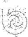
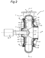
- An example of such a centrifugal pump is depicted in Fig.'s 1 and 2.
- Fig.'s 1 and 2 schematically depict an example of such a known centrifugal pump 1, both Figures showing a cross-sectional view in different directions.
- the pump 1 comprises a pump housing 2 shaped like a volute (spiral casing).
- the pump housing 2 comprises a circumferential wall 3, a pump casing 20 and a shaft cover 40.
- the circumferential wall 3 comprises a spout-shaped outlet 5 attached tangentially to the circumferential wall 3 .
- the junction between the inner surface of the tangential outlet 5 and the inner surface of the circumferential wall 3 of the pump housing 2 defines what is known as a cutwater 4.
- the pump housing 2 also has an axial inlet 6, shown in Fig. 2 .
- the circumferential wall 3 may have a U-shaped or semicircular cross-section, comprising two (parallel) legs 31 extending in a radial inward direction and a middle part connecting the two legs forming the outer wall 32 of the circumferential wall.
- This outer wall 32 may be a straight part or may be curved.
- the outer wall 32 spirals outwardly about the axial rotation axis A of the pump 1 (defined below) towards the tangential outlet 5.
- a rotor 7 is attached in the pump housing 2 such that it may rotate about an axial rotation axis A.
- the rotor 7 comprises rotor blades 15, a shaft shield 11 and a suction shield 12.
- the rotor 7 also comprises a central boss 9 which may be fastened to a drive shaft (51).
- the shaft shield 11 extends from the central boss 9.
- the shaft shield 11 forms a first wall for delimiting the flow within the rotor 7.
- the rotor 7 has the suction shield 12 which defines a second wall for delimiting the flow within the rotor 7.
- the suction shield 12 has an axial supply 14 which is aligned with the axial inlet of the pump housing 2.
- a plurality of rotor blades 15 are fastened between the shields 11, 12.
- the rotor 7 comprises three rotor blades 15.
- the rotor blades 15 each extend substantially radial to the rotation axis A.
- the circumferential wall 3 of the pump housing 2 substantially closes the inner space of the rotor 7 along its outer circumference between the shields 11, 12 and may have a rounded shape.
- the pump housing 2 further comprises a pump casing 20 and a shaft cover 40, both attached to the circumferential wall 3.
- the pump casing 20 is attached to the pump housing 2, i.e. to the circumferential wall 3, by suitable connection means 22.
- the pump casing 20 has a central opening which may form the axial supply 14 or may surround the axial supply 14.
- the pump casing 20 may comprise a stepped part 23 and reinforcing ribs 21 (not shown in Fig.'s 1 and 2).
- the term pump casing in this text is used to refer to a part of the pump housing 2 extending between the central opening to the circumferential wall 3.
- the pump casing 20 may also be referred to as the suction cover or suction lid 20.
- the shaft cover 40 (or shaft lid 40) is also attached to the circumferential wall 3 opposite the pump casing 20, by suitable connection means 42.
- the shaft cover 40 also has a central opening to allow a drive axis 51 of a pump motor 50 to be connected to the rotor 7.
- the drive axis 51 and the rotor 7 rotate about the rotation axis A.
- the mass to be pumped is forced radially outward into the pump housing 2 under the influence of centrifugal forces. Said mass is then entrained in the circumferential direction of the pump housing 2 toward the tangential outlet spout 5 of the pump housing 2.
- the pumped mass which, after leaving the rotor 7, is entrained in the circumferential direction of the pump housing 2 flows largely out of the tangential outlet of the pump housing 2.
- a small amount of the entrained mass re-circulates, i.e. flows along the cutwater 4 back into the pump housing 2.
- the pumps When such pumps are used for dredging, the pumps may be subjected to extreme wear, especially the rotor 7 and the circumferential wall 3. Therefore preferably wear resistant material is used.
- these materials are in general not well suited for construction purposes, as they are usually brittle.
- An example of such a material is white cast iron such as maxidur.
- connection means 22 may be transferred via connection means 22. From Fig. 2 it can be seen that these loads may introduce a bending moment in the circumferential wall 3 of the pump housing 2, as the leg 31 to which the pump casing 20 is attached is forced in an outward direction. To prevent introducing a bending moment, or keeping the bending moment relatively small, in the circumferential wall 3 of the pump housing 2, it is known to position the connection means 22 more outwardly than shown in Fig. 2 , i.e.
- centrifugal pumps and connection means for housings provided along the outer circumference are provided by DE2541422A1 , GB719285A , US3018736 (closest prior art), US3265002 , CN201661518 and FR567370A .
- WO2009149511 shows a pump assembly with a pump housing comprising two casting parts which are joined together about the periphery of the two side casing parts, without the use of a circumferential wall as described above.
- the two side casing parts comprise apertures to allow the two side casing parts to be joined together by bolts.
- One of the side casing parts also comprises apertures for receiving liner locating and fixing pins for locating the main liner or volute and the pump outer casing relative to another.
- a pump housing comprising a circumferential wall, a pump casing and a shaft cover, wherein the pump casing is attached to the circumferential wall by a plurality of connection means, and wherein the pump casing comprises a central opening to form an axial supply of the pump housing for material to be pumped, the circumferential wall closing the pump housing along an outer circumference of the pump housing, wherein the pump comprises a plurality of connection means connecting the pump casing to the circumferential wall, characterized in that the connection means are positioned in groups along the circumference of the pump housing, wherein the groups are regularly distributed along the circumference of the pump housing.
- connection means in groups a group comprising two or more connection means, and distributing the groups at regular intervals along the circumference of the pump housing, a strong and stiff pump housing is created, which can also be manufactured in an advantageous way.
- connection means in groups are not present in WO2009149511 ,
- the groups may be pairs comprising two connection means, whereby a pair is defined as two connection means with a distance between those two connection means which is at least 1/2 the distance between each connection means of that pair to the next closest connection means. This ratio may preferably be 1/3 or even 1/5.
- a group may also comprise more than two connection means, whereby a group is defined as a plurality of connection means whereby a largest distance between any two connection means of the group is at least 1/2 the distance between each connection means of that group to the next closest connection means of a different group. This ratio may preferably be 1/3 or even 1/5.
- the term regularly distributed is used to indicate that the groups or pairs are distributed along the circumference of the pump housing at substantially constant angles when seen from a centre point of the pump housing, i.e. at angles ⁇ equal to 360/n, n being an integer greater than 1, for instance 2, 3, 4, 5, 6, 7, 8, ....
- substantially constant is used to indicate that the different angles deviate less than 5%, preferably less than 2% with respect to each other.
- connection means in this text is used to refer to connection means capable of securing the pump casing to the circumferential wall.
- the connection means are arranged to withstand forces pushing the pump casing and the circumferential wall away from each other, in particular in a direction perpendicular to the interface of the pump casing and the circumferential wall. Such forces are generated inside the pump housing as a result of increased pressure inside the pump housing when the pump is in operation.
- connection means may be formed by a screw bolt and corresponding screw bolt receiving holes with an inner screw thread.
- receiving holes may be provided in the pump casing and the circumferential wall of which only the receiving holes in the circumferential wall are screw bolt receiving holes.
- the pump casing comprises a plurality of reinforcing ribs positioned radially with respect to the central opening, wherein the connection means are positioned adjacent reinforcing ribs.
- connection means By providing the connection means adjacent the reinforcing ribs, the pump is stronger and stiffer, which is beneficial to the performance of the pump.
- the connection means hold the pump casing in position.
- the connection means are now positioned close to the reinforcing ribs, i.e. at a position where the pump casing is relatively strong. This results in an improved stress distribution, making the pump relatively strong and stiff.
- the reinforcing ribs may extend from the axial supply towards the outer circumference of the pump casing.
- the ribs may have a triangular shape and may be orientated such that the height of the ribs reduces towards the outer circumference of the pump casing.
- the ribs may be uniformly distributed.
- the circumferential wall closes the pump housing along its outer circumference, but it will be understood that the circumferential wall may also comprise an outlet for the pumped materials.
- connection means and the nearest reinforcing rib are at least 5 times smaller than the distance between the connection means and the second nearest reinforcing rib. Preferably, this distance may be at least 10 times smaller.
- connection means of a group are positioned on opposite sides of the adjacent reinforcing rib.
- connection means forming a group or pair may be provided on opposite sides of the reinforcing ribs to provide a strong and symmetric construction.
- the connection means forming a pair may be positioned at the same distance from the associated reinforcing rib at opposite sides of the reinforcing rib.
- Each reinforcing rib 21 may be provided with a pair of connection means 22, possibly with an exception for a minority of reinforcing ribs 21, e.g. one or two reinforcing ribs 21, which may be left without connection means 22 to meet certain constructional requirements or the like.
- connection means By placing connection means on either side of the reinforcing ribs the construction becomes even stiffer and the even stress distribution results in lower stresses.
- connection means may be provided, wherein a group comprises two, three, four or more connection means to provide an even stronger pump housing.
- connection means or pairs of connection means may be regularly distributed along the outer circumference, one or two connection means may be omitted, as already indicated above.
- connection means which may be bolt receiving structures provided on the outside of the outer circumference may also function as casting inlets for the casting material (such as liquid steel) during the casting process.
- connection means are provided in pairs, an additional advantage is provided.
- One casting inlet may then be provided for each pair. This allows a relatively large casting inlet, which is beneficial, as the casting material needs to be supplied to the mould sufficiently fast such that it can spread through the mould before it is solidified.
- connection means are positioned along the outer circumference of the pump and connect the pump casing to a radial outer wall of the circumferential wall.
- connection means along the outer circumference provides an even stronger and stiffer pump as bending moments in the circumferential wall, especially in the radial inwardly protruding legs of the circumferential wall are minimized and the connection means engage the circumferential wall at the outer wall, i.e. at a position where the circumferential wall is relatively thick in the axial direction.
- connection means are formed by a connection member, such as a bolt, and bolt receiving holes provided on the circumferential wall and bolt receiving holes provided on the pump casing.
- the connection member may be a screw bolt.
- One or both of the bolt receiving holes may be a screw bolt receiving hole comprising an inner thread to receive the screw bolt and hold the screw bolt in position.
- a soft insert may be used.
- the material used for the pump housing is typically wear resistant material, i.e. it is hard but brittle, which is thus, mechanically and production wise, not well suited for threaded holes.
- An example of such a material is steel S235.
- a soft insert may be applied which is more suitable for providing an inner thread.
- the bolt receiving holes provided on the circumferential wall and the bolt receiving holes provided on the pump casing are aligned with respect to each other.
- the circumferential wall comprises bolt receiving structures provided on the outer circumference of the circumferential wall.
- the bolt receiving structures may protrude in a radial outward direction.
- the bolt receiving structures may be integrally formed with the circumferential wall. This provides a robust circumferential wall. This embodiment also provides advantages for the manufacturing process, as will be described in more detail below.
- each bolt receiving structure comprises at least two bolt receiving holes.
- the bolt receiving holes may not be positioned too close to each other, especially when soft inserts are used. As a consequence, the bolt receiving structures may not be too small.
- Such bolt receiving structures provide advantages in the manufacturing process. Also, such a design minimizes the amount of material that is needed.
- a pump comprising a pump housing according to the above.
- a circumferential wall of a pump housing the circumferential wall comprises a spiral shaped outer wall and two inwardly protruding legs attached to the outer wall, wherein the circumferential wall comprises bolt receiving holes which are positioned in groups along the circumference of the circumferential wall, wherein the groups are regularly distributed along the circumference of the circumferential wall.
- the bolt receiving holes may be screw bolt receiving holes provided with an inner thread.
- a method of manufacturing a circumferential wall for a pump housing and wherein the circumferential wall comprises bolt receiving holes provided on the outside of the circumferential wall, wherein the method comprises:
- the circumferential wall comprises bolt receiving structures provided on the outer circumference of the circumferential wall, which bolt receiving structures coincide with the casting openings and/or function as risers during casting.
- the design of the circumferential wall in combination with the positioning of the casting openings provides an advantageous method of manufacturing a circumferential wall.
- the bolt receiving structures which may be formed as a structure protruding in a radial outward direction from the spiral shaped outer wall provides an optimal structure for the casting openings of the mould.
- such bolt receiving structures are suitable to be used as risers, especially since the connecting means are provided in groups making the bolt receiving structures relatively large.
- risers are not too small as this will cause the casting material to solidify too quickly prohibiting the riser to function properly.
- each bolt receiving structure comprises at least two bolt receiving holes.
- Such bolt receiving structures will typically be larger than bolt receiving structures for one bolt receiving hole, making these bolt receiving structures even more suitable to be used as casting inlets, as relative large quantities of casting material may be supplied into the mould via each cast opening, allowing a fast casting process.
- the casting material is one of steel, cast steel, grey or white cast iron.
- Fig.'s 1 and 2 show a pump according to the prior art and were discussed above.
- Fig. 3 shows an embodiment of a pump 1, a centrifugal pump, comprising a pump housing 2 with a circumferential wall 3, a pump casing 20 and a shaft cover 40 as described above.
- the circumferential wall spirals outwardly to form a tangential outlet 5, as shown in the figures.
- the pump housing 2 may be suitable for pumping a slurry comprising a mixture of water and dredged materials, such as sand, rocks etc. Therefore, the pump 1 is arranged to accommodate a rotor 7 comprising rotor blades 15, a shaft shield 11 and a suction shield 12 as described above.
- the pump casing 20 is formed as a lid arranged to cover the pump housing 2 and provide the pump housing 2 with additional strength.
- the pump casing 20 has a substantially disc shaped part 26, although the disc shaped part 26 may not have a circular outer circumference, as it may deviate from a circular shape at the position of the outlet 5.
- a central opening 27 is provided to allow mass to be pumped to enter the pump housing 2 via the axial inlet 6 and axial supply 14.
- an inlet conduit 28 may be formed as integral part of the pump casing 20, the inlet conduit 28 protruding from the pump casing 20 in the direction of the axial rotation axis A, away from the shaft cover 40 (not shown in Fig. 3 ).
- the inlet conduit 28 may form the axial inlet 6.
- the pump casing 20 comprises a stepped part 23 forming a transition between the disc shaped part 26 and the inlet conduit 28, making the pump casing 20 strong. Furthermore, a plurality of reinforcing ribs 21 are provided. Each reinforcing rib 21 is substantially perpendicular with respect to the disc shaped part 26 and each reinforcing rib 21 is orientated in a different radial direction.
- a shaft cover 40 forming the counterpart of the pump casing 20, positioned on the shaft side of the pump housing.
- the shaft cover 40 also comprises a central opening to allow the drive shaft 51 of motor 50 to pass through and drive the rotor 7 to rotate about axis A.
- connection means 22 (connecting the pump casing 20 to the circumferential wall 3) are provided in groups, such as pairs, positioned regularly, i.e. at regular intervals. This will be explained in more detail below with reference to Fig. 6 .
- connection means 22 are also positioned adjacent the reinforcing ribs 21.
- the term adjacent is used her to indicate that that the connection means 22 are positioned close to a reinforcing rib 21, for instance at least 5 times, preferably at least 10 times closer to the closest reinforcing rib 21 than to the second closest reinforcing rib 21.
- connection means 22 may also be positioned close to the outer circumference of the pump casing 20, such that the connection means 22 engage the circumferential wall 3 at the position of the radial outer wall 32.
- the term 'close to' is used to indicate that the distance between the connection means 22 and the outer circumference of the pump casing 20 is less than 25%, or preferably less than 10%, of the radius of the pump casing 20, measured from the centre of the central opening 27 to the outer circumference of the disc shaped part 26.
- connection means 22 are provided in pairs, i.e. each reinforcing rib 21 has two associated, adjacent, connection means 20, which are provided symmetrically on both sides of the reinforcing rib 21.
- connection means 22 may be provided in association with one reinforcing rib 21.
- a group of connection means 22 may be provided in association with a reinforcing rib 21.
- connection means 22 are provided for each reinforcing rib 21.
- some reinforcing ribs 21 may be without associated connection means 22, for instance the reinforcing ribs 21' near the outlet 5.
- connection means 22 may be any suitable connection means 22, such as clamping devices clamping the pump casing against the circumferential wall 3 or clamping the pump casing 20 and the shaft cover 40 together squeezing them against the circumferential wall 3.
- connection means 22 may be formed by a connection member 223, such as a bolt, and a corresponding bolt receiving hole 224 provided on the circumferential wall 3 and a bolt receiving hole 222 provided on the pump casing 20. This is shown in more detail in Fig. 5 , showing part of the circumferential wall 3 and the pump casing 20.
- the circumferential wall 3 may be provided with bolt receiving members or bolt receiving structures 221 provided on the outer circumference of the circumferential wall 3, protruding from the spiral outer shape of the outer wall 32 of the circumferential wall 3, and comprising bolt receiving holes 21.
- the dashed line L shown in Fig. 5 shows the contour of the circumferential wall 3 as it would be without the bolt receiving structure 221, clearly showing that the bolt receiving structure 221 protrudes from the outer wall of the circumferential wall 3.
- One bolt receiving structure or structure 221 may comprise one or two bolt receiving holes 21.
- the bolt receiving holes 222, 224 are parallel to the axial rotation axis A of the pump, i.e. parallel to the direction in which the internal pressure of the pump 1 will try to move the pump casing 20.
- Fig. 5 further shows that the pump casing 20 may comprise annular slots 241 in which sealing members 242, such as O-rings, may be positioned to provide a fluid-tight connection between the circumferential wall 3 and the pump casing 20.
- sealing members 242 such as O-rings
- the circumferential wall 3 may be provided with soft inserts 228 which are suitable for forming a threaded bolt receiving hole 224 therein.
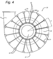
- Fig. 4 shows a side view of the pump 1 in the direction of the axial supply 14. It can be seen that the reinforcing ribs 21 are all orientated in a different radial direction at regular mutual angles ⁇ .
- the reinforcing rib 21 or reinforcing ribs 21 close to the outlet 5 may be a bit longer or shorter in radial direction to follow the irregularity of the outer circumference of the pump casing 20 and the circumferential wall 3.
- connection means 22 will now be explained in more detailwith reference to Fig. 6a- b , showing a view of the pump housing 20 in the direction of the rotation axis A.
- connection means 22 may be positioned in groups, such as pairs ( Fig. 6a ) or in larger groups, for instance comprising four connection means 22, as shown in Fig. 6b .
- the groups are positioned along the circumference of the pump housing 2 and are regularly distributed along the circumference of the pump housing 2.
- a group may be defined as a number of connection means 22 that are relatively close to each other compared to other connection means 22 which thus not belong to that group.
- a group may be defined as a plurality of connection means 22 whereby a largest distance between any two connection means of the group (d1 in Fig. 6b ) is at least 1/2 the distance between each connection means of that group to the next closest connection means of a different group (d2 in Fig. 6b ).
- This ratio may preferably be 1/3 or even 1/5.
- This definition also applies to a group of two connection means 22.
- Fig. 6a also shows distances d1 and d2, whereby d1 ⁇ 1 ⁇ 2d2, preferably d1 ⁇ 1/3 d2 or d1 ⁇ 1/5 d2.
- the term regularly distributed is used to indicate that the groups are distributed along the circumference of the pump housing 2 at substantially constant angles ⁇ as shown in Fig.'s 6a - b when seen from a centre point of the pump housing 2.
- substantially constant is used to indicate that the different angles deviate less than 5°, preferably less than 2° with respect to each other.
- the term regularly distributed may be used to indicate that the groups are distributed along the circumference of the pump housing 2 at substantially constant intervals.
- the term constant is used to indicate that these distances do not deviate more than 15%, preferably less than 10%.
- the groups are regularly distributed along a substantial part of the circumference of the pump housing 2, whereby the substantial part of the circumference of the pump housing 2 forms at least 75% of the total circumference, so is at least 270°.
- Manufacturing a pump 1 or a pump housing 2 as described above may involve casting one or more of the pump parts, such as the circumferential wall 3.
- the bolt receiving structures 221 or bolt receiving structures provided on the outer circumference of the circumferential wall 3, protruding from the outer wall of the circumferential wall 3 allow for an advantageous casting process.
- the casting mould is provided with casting openings to supply casting material into the mould.
- the bolt receiving structures 221 can be aligned with the casting openings of the mould providing an excellent structure for supplying the casting material into the casting mould. This saves material and thus cost with respect to supplying casting material at other positions.
- the bolt receiving structures 221 can advantageously function as risers.
- the casing material inside the mould will solidify and thus shrink.
- Risers can function as a buffer reservoir for casting material. Once the material inside the mould has shrunk, the space in between the mould and the shrunk casting material will be filled with casting material from the risers. The risers may not be too small, as this will cause the casting material to cool down relatively quickly compared to the cooling of the rest of the casting material in the mould.
- connection means 42 may also be positioned in groups along the circumference of the pump housing 2, wherein the groups are regularly distributed along the circumference of the pump housing 2.
- the shaft cover 40 may comprises a plurality of reinforcing ribs positioned radially with respect to a central opening for the drive shaft, wherein the connection means 42 are positioned adjacent the reinforcing ribs.
- the connection means 42 of a group may be positioned on opposite sides of the adjacent reinforcing rib.
- the connection means may be positioned along the outer circumference of the pump 1 and connect the shaft cover 40 to a radial outer wall 32 of the circumferential wall 3.
- connection means 42 may be formed by a connection member, such as a bolt, and bolt receiving holes provided on the circumferential wall 3 and bolt receiving holes provided on the shaft cover 40.
- the circumferential wall 3 may comprise bolt receiving structures provided on the outer circumference of the circumferential wall. Each bolt receiving structure may comprise two bolt receiving holes.
- the embodiments described provide a pump, which is relatively strong and stiff.
- the pump can be casted in an efficient way, still resulting in a pump which is strong and stiff.
Landscapes
- Engineering & Computer Science (AREA)
- Mechanical Engineering (AREA)
- General Engineering & Computer Science (AREA)
- Structures Of Non-Positive Displacement Pumps (AREA)
Claims (8)
- Pumpengehäuse (2), umfassend eine Umfangswand (3), einen Pumpenkörper (20) und eine Welleneinfassung (40), wobei der Pumpenkörper (20) an der Umfangswand (3) befestigt ist, und wobei der Pumpenkörper (20) eine mittlere Öffnung (27) aufweist, die eine axiale Zuführung (14) des Pumpengehäuses (2) für zu pumpenden Stoff bildet, die Umfangswand (3) eine Außenwand des Pumpengehäuses (2) ist,
wobei das Pumpengehäuse (2) Verbindungsmittel (22) aufweist, die den Pumpenkörper (20) mit der Umfangswand (3) verbinden,
wobei die Verbindungsmittel (22) in Gruppen über den Umfang des Pumpengehäuses (2) angeordnet sind, jede Gruppe eine Vielzahl von Verbindungsmitteln (22) umfasst, wobei die Gruppen regelmäßig über den Umfang des Pumpengehäuses (2) verteilt sind, wobei die Verbindungsmittel (22) durch Schrauben und auf der Umfangswand (3) vorgesehene Schraubenaufnahmebohrungen (224) sowie auf dem Pumpenkörper (20) vorgesehene Schraubenaufnahmebohrungen(222) ausgebildet sind, wobei die Umfangswand (3) Schraubenaufnahmestrukturen (221) umfasst, die auf dem äußeren Umfang der Umfangswand (3) vorgesehen sind, wobei die Schraubenaufnahmestrukturen in einer Richtung radial nach außen vorstehen, dadurch gekennzeichnet das jede Schraubenaufnahmestruktur (221) mindestens zwei Schraubenaufnahmebohrungen (224) aufweist. - Pumpengehäuse (2) nach Anspruch 1, wobei der Pumpenkörper (20) eine Vielzahl von Verstärkungsrippen (21) aufweist, die bezüglich der mittleren Öffnung (27) radial angeordnet sind, wobei die Verbindungsmittel (22) den Verstärkungsrippen (21) benachbart angeordnet sind.
- Pumpengehäuse (2) nach Anspruch 2, wobei die Verbindungsmittel (22) einer Gruppe auf gegenüberliegenden Seiten der benachbarten Verstärkungsrippe (21) angeordnet sind.
- Pumpengehäuse (2) nach einem der vorhergehenden Ansprüche, wobei die Verbindungsmittel (22) über den äußeren Umfang des Pumpengehäuses (2) angeordnet sind und den Pumpenkörper (20) mit einer radialen Außenwand (32) der Umfangswand (3) verbinden.
- Pumpe (1), umfassend ein Pumpengehäuse (2) nach einem der vorhergehenden Ansprüche 1-4.
- Umfangswand (3) eines Pumpengehäuses (2), wobei die Umfangswand (3) eine spiralförmige Außenwand (32) und zwei nach innen vorstehende Schenkel (31) aufweist, die an der Außenwand (32) befestigt sind, wobei die Umfangswand (3) Schraubenaufnahmestrukturen (221) umfasst, die auf dem äußeren Umfang der Umfangswand (3) vorgesehen sind, wobei die Schraubenaufnahmestrukturen in einer Richtung radial nach außen vorstehen, die Schraubenaufnahmestrukturen (221) Schraubenaufnahmebohrungen (224) umfassen, dadurch gekennzeichnet, dass die Schraubenaufnahmestrukturen (221) in Gruppen über den Umfang der Umfangswand (3) angeordnet sind, wobei die Gruppen regelmäßig über den Umfang der Umfangswand (3) verteilt sind, wobei jede Schraubenaufnahmestruktur (221) mindestens zwei Schraubenaufnahmebohrungen (224) umfasst.
- Verfahren zur Herstellung einer Umfangswand (3) für ein Pumpengehäuse (2), wobei die Umfangswand (3) Schraubenaufnahmebohrungen (224) aufweist, die auf der Außenseite der Umfangswand (33) vorgesehen sind, wobei das Verfahren umfasst:- Bereitstellen einer Form für die Umfangswand (3), wobei die Form eine Vielzahl von Gießöffnungen aufweist;- Füllen der Form mit einem flüssigen Gießwerkstoff, indem der Gießwerkstoff über die Gießöffnungen der Form zugeführt wird;- Erstarren lassen des Gießwerkstoffs in der Form;- Entfernen der Form;gekennzeichnet durch die Schraubenaufnahmebohrungen (224), die in Gruppen über den Umfang der Umfangswand (3) angeordnet sind, wobei die Gruppen regelmäßig über den Umfang der Umfangswand (3) verteilt sind, wobei die Umfangswand (3) Schraubenaufnahmestrukturen (221) umfasst, die auf dem äußeren Umfang der Umfangswand (3) vorgesehen sind, wobei die Schraubenaufnahmestrukturen (221) in einer Richtung radial nach außen vorstehen, wobei jede Schraubenaufnahmestruktur (221) mindestens zwei Schraubenaufnahmebohrungen (224) aufweist, wobei die Schraubenaufnahmestrukturen mit den Gießöffnungen übereinstimmen und/oder während des Gießens als Steiger funktionieren.
- Verfahren nach Anspruch 7, wobei der Gießwerkstoff einer von Stahl, Gussstahl, Gusseisen mit Lamellengraphit oder Hartguss ist.
Applications Claiming Priority (2)
| Application Number | Priority Date | Filing Date | Title |
|---|---|---|---|
| NL2008180A NL2008180C2 (en) | 2012-01-25 | 2012-01-25 | Pump and a method of manufacturing such a pump. |
| PCT/NL2013/050030 WO2013112045A1 (en) | 2012-01-25 | 2013-01-23 | Pump and a method of manufacturing such a pump |
Publications (3)
| Publication Number | Publication Date |
|---|---|
| EP2807376A1 EP2807376A1 (de) | 2014-12-03 |
| EP2807376B1 true EP2807376B1 (de) | 2016-01-20 |
| EP2807376B8 EP2807376B8 (de) | 2016-03-16 |
Family
ID=47710276
Family Applications (1)
| Application Number | Title | Priority Date | Filing Date |
|---|---|---|---|
| EP13703902.0A Active EP2807376B8 (de) | 2012-01-25 | 2013-01-23 | Pumpe und verfahren zur herstellung einer solchen pumpe |
Country Status (7)
| Country | Link |
|---|---|
| US (1) | US9726193B2 (de) |
| EP (1) | EP2807376B8 (de) |
| CN (1) | CN104204534B (de) |
| ES (1) | ES2563236T3 (de) |
| NL (1) | NL2008180C2 (de) |
| WO (1) | WO2013112045A1 (de) |
| ZA (1) | ZA201405507B (de) |
Cited By (1)
| Publication number | Priority date | Publication date | Assignee | Title |
|---|---|---|---|---|
| GB2548472B (en) * | 2016-02-09 | 2021-07-28 | Brunswick Corp | Centrifugal pumps having anti-air-locking features |
Families Citing this family (9)
| Publication number | Priority date | Publication date | Assignee | Title |
|---|---|---|---|---|
| USD751685S1 (en) * | 2013-08-06 | 2016-03-15 | Shinano Kenshi Co., Ltd. | Blower |
| BR112017002009B1 (pt) * | 2014-07-31 | 2022-09-06 | Weir Minerals Australia Ltd | Revestimento de bomba para uma bomba centrífuga e método para produzir uma parte lateral de um revestimento de bomba para uma bomba centrífuga |
| CN106968984B (zh) * | 2015-12-11 | 2020-10-23 | 松下知识产权经营株式会社 | 涡轮机 |
| US10339962B2 (en) | 2017-04-11 | 2019-07-02 | Texas Instruments Incorporated | Methods and apparatus for low cost voice activity detector |
| CN109210009A (zh) * | 2018-10-09 | 2019-01-15 | 浙江亿迈达泵业有限公司 | 一种泵体前端盖、泵体及磁力泵 |
| NL2022881B1 (en) | 2019-04-05 | 2020-10-12 | Ihc Holland Ie Bv | Pump |
| DE102019115741A1 (de) * | 2019-06-11 | 2020-12-17 | Ebm-Papst Landshut Gmbh | Versteiftes Gebläsegehäuseteil zur Anordnung an einem Gasgebläse |
| RU195238U1 (ru) * | 2019-10-03 | 2020-01-17 | Акционерное общество (АО) "Турбонасос" | Корпус центробежного насоса для перекачки абразивсодержащих сред |
| CN115095532A (zh) * | 2022-06-10 | 2022-09-23 | 广东易得电器有限公司 | 一种循环洗涤泵 |
Family Cites Families (30)
| Publication number | Priority date | Publication date | Assignee | Title |
|---|---|---|---|---|
| NL111055C (de) | ||||
| FR567370A (fr) | 1923-06-13 | 1924-02-29 | Pompes en plomb armé pour acides | |
| US2537084A (en) * | 1948-09-04 | 1951-01-09 | Morris Machine Works | Fabricated centrifugal pump |
| GB719285A (en) | 1951-10-03 | 1954-12-01 | British Thomson Houston Co Ltd | Improvements in rotary liquid pumps |
| US2856858A (en) * | 1953-07-13 | 1958-10-21 | Grace W R & Co | Centrifugal pump |
| US3018736A (en) | 1954-01-04 | 1962-01-30 | Hetherington & Berner Inc | Dredge pump |
| US2976809A (en) | 1954-08-11 | 1961-03-28 | Buschhorn Walther | Centrifugal pump and method of its production |
| DE1112897B (de) | 1958-05-20 | 1961-08-17 | Schauenburg Hans Georg | Pumpengehaeuse mit aus Ringen aufgebautem Gehaeusemantel |
| GB867802A (en) | 1959-07-18 | 1961-05-10 | Mervyn Joseph Alexander Carrie | Improvements in rotary gravel or like pumps |
| US3265002A (en) * | 1961-01-13 | 1966-08-09 | Res & Dev Pty Ltd | Centrifugal pumps and the like |
| US3333872A (en) * | 1964-11-18 | 1967-08-01 | Standard Fire Prot Equipment C | Mechanical pipe joint construction |
| US3473573A (en) * | 1966-10-06 | 1969-10-21 | Baker Mfg Co | Well cap and seal therefor |
| US3465681A (en) * | 1967-08-24 | 1969-09-09 | March Mfg Co | Magnetically-coupled pump with detachable motor |
| SE428957B (sv) * | 1975-06-02 | 1983-08-01 | Warman Int Ltd | Invendigt fodrat hogtryckspumphus |
| SE429255B (sv) * | 1975-06-13 | 1983-08-22 | Warman Int Ltd | Hus och foder for centrifugalpumpar av snecktyp |
| DE2541422B2 (de) | 1975-09-17 | 1979-04-05 | Schmalenberger Gmbh & Co, 7400 Tuebingen | Motorpumpeneinheit mit einem mindestens aus zwei Gehäusehälften bestehenden Pumpengehäuse |
| GB1517400A (en) | 1975-12-17 | 1978-07-12 | Mitsui Mining & Smelting Co | Impeller-type pump |
| DE2837986C2 (de) * | 1978-08-31 | 1984-04-12 | Elektro-Thermit Gmbh, 4300 Essen | Gießform zur aluminothermischen Schienenverbindungsschweißung |
| US6267268B1 (en) * | 1999-08-31 | 2001-07-31 | The Coca-Cola Company | Mounting block for syrup pump and accessories |
| GB2391266A (en) * | 1999-10-06 | 2004-02-04 | Vaughan Co | Impeller and intake arrangement for a centrifugal pump |
| US7470106B1 (en) * | 2001-07-10 | 2008-12-30 | Townley Manufacturing, Inc. | Centrifugal slurry pump |
| JP4484470B2 (ja) * | 2002-10-23 | 2010-06-16 | エドワーズ株式会社 | 分子ポンプ、及びフランジ |
| EP1903216B1 (de) | 2006-09-18 | 2009-10-28 | IHC Holland IE B.V. | Zentrifugalpumpe und deren Anwendung |
| EP1906029B1 (de) | 2006-09-19 | 2009-12-16 | IHC Holland IE B.V. | Kreiselpumpe mit Innen- und Aussengehäuse |
| DE202007018626U1 (de) | 2007-07-19 | 2009-04-02 | Elektror K.W. + M. Müller GmbH | Gebläseeinrichtung |
| CN201106566Y (zh) * | 2007-09-05 | 2008-08-27 | 林心怡 | 污水处理泵的改良结构 |
| ES2528237T3 (es) * | 2008-06-13 | 2015-02-06 | Weir Minerals Australia Ltd | Mejoras referentes a conjuntos de estanqueidad para bombas |
| CN201273302Y (zh) * | 2008-09-19 | 2009-07-15 | 沈阳鼓风机集团有限公司 | 一种筒形压缩机端盖与筒体的装配结构 |
| FR2949517B1 (fr) | 2009-08-25 | 2011-10-21 | Snecma | Carter de turbomachine a etancheite renforcee |
| CN201661518U (zh) * | 2010-02-03 | 2010-12-01 | 李正奇 | 多级离心泵用出水段 |
-
2012
- 2012-01-25 NL NL2008180A patent/NL2008180C2/en not_active IP Right Cessation
-
2013
- 2013-01-23 US US14/374,597 patent/US9726193B2/en active Active
- 2013-01-23 ES ES13703902.0T patent/ES2563236T3/es active Active
- 2013-01-23 WO PCT/NL2013/050030 patent/WO2013112045A1/en not_active Ceased
- 2013-01-23 EP EP13703902.0A patent/EP2807376B8/de active Active
- 2013-01-23 CN CN201380016384.XA patent/CN104204534B/zh active Active
-
2014
- 2014-07-25 ZA ZA2014/05507A patent/ZA201405507B/en unknown
Cited By (1)
| Publication number | Priority date | Publication date | Assignee | Title |
|---|---|---|---|---|
| GB2548472B (en) * | 2016-02-09 | 2021-07-28 | Brunswick Corp | Centrifugal pumps having anti-air-locking features |
Also Published As
| Publication number | Publication date |
|---|---|
| US9726193B2 (en) | 2017-08-08 |
| WO2013112045A1 (en) | 2013-08-01 |
| EP2807376B8 (de) | 2016-03-16 |
| CN104204534A (zh) | 2014-12-10 |
| US20140348645A1 (en) | 2014-11-27 |
| ZA201405507B (en) | 2015-10-28 |
| NL2008180C2 (en) | 2013-07-29 |
| EP2807376A1 (de) | 2014-12-03 |
| CN104204534B (zh) | 2017-10-17 |
| ES2563236T3 (es) | 2016-03-11 |
Similar Documents
| Publication | Publication Date | Title |
|---|---|---|
| EP2807376B1 (de) | Pumpe und verfahren zur herstellung einer solchen pumpe | |
| EP2542784B1 (de) | Pumpeneinlassvorrichtung | |
| RU2551909C2 (ru) | Центробежное рабочее колесо и турбомашина | |
| CN101624989B (zh) | 泵 | |
| US7780406B2 (en) | Molded pump | |
| CA2831985C (en) | An improved impeller for a centrifugal slurry pump | |
| CA1270148A (en) | Vane core assembly for use in making centrifugal elastomer-coated impellers | |
| US9410529B2 (en) | Rotor blade for a wind turbine | |
| EP3559477B1 (de) | Laufrad mit rotorblättern für kreiselpumpe | |
| CN104603451B (zh) | 一种用于液压流体机的叶轮装置 | |
| KR20230025929A (ko) | 원심 펌프의 3차원 플라스틱 임펠러 | |
| EP1028256B1 (de) | Laufrad für elektrisch angetriebene Fahrzeugbrennstoffpumpe | |
| US20110182734A1 (en) | Centrifugal pump impeller | |
| JP5984588B2 (ja) | 水ポンプ用羽根車 | |
| US1107591A (en) | Pump construction. | |
| CA2667497C (en) | Hydraulic machine | |
| EP3947977B1 (de) | Pumpe | |
| CN202946437U (zh) | 二代加核主泵推力轴承油叶轮 | |
| CN116806292A (zh) | 用于泵的主衬垫 | |
| WO2025160622A1 (en) | Front side liner for a pump | |
| WO2018049439A1 (en) | Volute liner arrangement | |
| Yedidiah | Axial and Radial Thrust and Balancing |
Legal Events
| Date | Code | Title | Description |
|---|---|---|---|
| PUAI | Public reference made under article 153(3) epc to a published international application that has entered the european phase |
Free format text: ORIGINAL CODE: 0009012 |
|
| 17P | Request for examination filed |
Effective date: 20140822 |
|
| AK | Designated contracting states |
Kind code of ref document: A1 Designated state(s): AL AT BE BG CH CY CZ DE DK EE ES FI FR GB GR HR HU IE IS IT LI LT LU LV MC MK MT NL NO PL PT RO RS SE SI SK SM TR |
|
| DAX | Request for extension of the european patent (deleted) | ||
| GRAP | Despatch of communication of intention to grant a patent |
Free format text: ORIGINAL CODE: EPIDOSNIGR1 |
|
| INTG | Intention to grant announced |
Effective date: 20150731 |
|
| GRAS | Grant fee paid |
Free format text: ORIGINAL CODE: EPIDOSNIGR3 |
|
| GRAA | (expected) grant |
Free format text: ORIGINAL CODE: 0009210 |
|
| AK | Designated contracting states |
Kind code of ref document: B1 Designated state(s): AL AT BE BG CH CY CZ DE DK EE ES FI FR GB GR HR HU IE IS IT LI LT LU LV MC MK MT NL NO PL PT RO RS SE SI SK SM TR |
|
| REG | Reference to a national code |
Ref country code: GB Ref legal event code: FG4D |
|
| REG | Reference to a national code |
Ref country code: CH Ref legal event code: EP |
|
| REG | Reference to a national code |
Ref country code: IE Ref legal event code: FG4D |
|
| GRAT | Correction requested after decision to grant or after decision to maintain patent in amended form |
Free format text: ORIGINAL CODE: EPIDOSNCDEC |
|
| REG | Reference to a national code |
Ref country code: AT Ref legal event code: REF Ref document number: 771865 Country of ref document: AT Kind code of ref document: T Effective date: 20160215 |
|
| RAP2 | Party data changed (patent owner data changed or rights of a patent transferred) |
Owner name: IHC HOLLAND IE B.V. |
|
| REG | Reference to a national code |
Ref country code: DE Ref legal event code: R096 Ref document number: 602013004739 Country of ref document: DE |
|
| REG | Reference to a national code |
Ref country code: ES Ref legal event code: FG2A Ref document number: 2563236 Country of ref document: ES Kind code of ref document: T3 Effective date: 20160311 |
|
| REG | Reference to a national code |
Ref country code: DE Ref legal event code: R082 Ref document number: 602013004739 Country of ref document: DE Representative=s name: KILBURN & STRODE LLP, NL Ref country code: DE Ref legal event code: R082 Ref document number: 602013004739 Country of ref document: DE Representative=s name: KILBURN & STRODE LLP, GB Ref country code: DE Ref legal event code: R081 Ref document number: 602013004739 Country of ref document: DE Owner name: IHC HOLLAND IE B.V., NL Free format text: FORMER OWNER: IHC HOLLAND IE N.V., SLIEDRECHT, NL |
|
| REG | Reference to a national code |
Ref country code: NL Ref legal event code: FP |
|
| REG | Reference to a national code |
Ref country code: LT Ref legal event code: MG4D |
|
| REG | Reference to a national code |
Ref country code: AT Ref legal event code: MK05 Ref document number: 771865 Country of ref document: AT Kind code of ref document: T Effective date: 20160120 |
|
| PG25 | Lapsed in a contracting state [announced via postgrant information from national office to epo] |
Ref country code: HR Free format text: LAPSE BECAUSE OF FAILURE TO SUBMIT A TRANSLATION OF THE DESCRIPTION OR TO PAY THE FEE WITHIN THE PRESCRIBED TIME-LIMIT Effective date: 20160120 Ref country code: NO Free format text: LAPSE BECAUSE OF FAILURE TO SUBMIT A TRANSLATION OF THE DESCRIPTION OR TO PAY THE FEE WITHIN THE PRESCRIBED TIME-LIMIT Effective date: 20160420 Ref country code: IT Free format text: LAPSE BECAUSE OF FAILURE TO SUBMIT A TRANSLATION OF THE DESCRIPTION OR TO PAY THE FEE WITHIN THE PRESCRIBED TIME-LIMIT Effective date: 20160120 Ref country code: FI Free format text: LAPSE BECAUSE OF FAILURE TO SUBMIT A TRANSLATION OF THE DESCRIPTION OR TO PAY THE FEE WITHIN THE PRESCRIBED TIME-LIMIT Effective date: 20160120 Ref country code: GR Free format text: LAPSE BECAUSE OF FAILURE TO SUBMIT A TRANSLATION OF THE DESCRIPTION OR TO PAY THE FEE WITHIN THE PRESCRIBED TIME-LIMIT Effective date: 20160421 |
|
| PG25 | Lapsed in a contracting state [announced via postgrant information from national office to epo] |
Ref country code: PT Free format text: LAPSE BECAUSE OF FAILURE TO SUBMIT A TRANSLATION OF THE DESCRIPTION OR TO PAY THE FEE WITHIN THE PRESCRIBED TIME-LIMIT Effective date: 20160520 Ref country code: LV Free format text: LAPSE BECAUSE OF FAILURE TO SUBMIT A TRANSLATION OF THE DESCRIPTION OR TO PAY THE FEE WITHIN THE PRESCRIBED TIME-LIMIT Effective date: 20160120 Ref country code: RS Free format text: LAPSE BECAUSE OF FAILURE TO SUBMIT A TRANSLATION OF THE DESCRIPTION OR TO PAY THE FEE WITHIN THE PRESCRIBED TIME-LIMIT Effective date: 20160120 Ref country code: SE Free format text: LAPSE BECAUSE OF FAILURE TO SUBMIT A TRANSLATION OF THE DESCRIPTION OR TO PAY THE FEE WITHIN THE PRESCRIBED TIME-LIMIT Effective date: 20160120 Ref country code: IS Free format text: LAPSE BECAUSE OF FAILURE TO SUBMIT A TRANSLATION OF THE DESCRIPTION OR TO PAY THE FEE WITHIN THE PRESCRIBED TIME-LIMIT Effective date: 20160520 Ref country code: LT Free format text: LAPSE BECAUSE OF FAILURE TO SUBMIT A TRANSLATION OF THE DESCRIPTION OR TO PAY THE FEE WITHIN THE PRESCRIBED TIME-LIMIT Effective date: 20160120 Ref country code: AT Free format text: LAPSE BECAUSE OF FAILURE TO SUBMIT A TRANSLATION OF THE DESCRIPTION OR TO PAY THE FEE WITHIN THE PRESCRIBED TIME-LIMIT Effective date: 20160120 Ref country code: PL Free format text: LAPSE BECAUSE OF FAILURE TO SUBMIT A TRANSLATION OF THE DESCRIPTION OR TO PAY THE FEE WITHIN THE PRESCRIBED TIME-LIMIT Effective date: 20160120 |
|
| REG | Reference to a national code |
Ref country code: CH Ref legal event code: PL |
|
| REG | Reference to a national code |
Ref country code: DE Ref legal event code: R097 Ref document number: 602013004739 Country of ref document: DE |
|
| PG25 | Lapsed in a contracting state [announced via postgrant information from national office to epo] |
Ref country code: EE Free format text: LAPSE BECAUSE OF FAILURE TO SUBMIT A TRANSLATION OF THE DESCRIPTION OR TO PAY THE FEE WITHIN THE PRESCRIBED TIME-LIMIT Effective date: 20160120 Ref country code: LI Free format text: LAPSE BECAUSE OF NON-PAYMENT OF DUE FEES Effective date: 20160131 Ref country code: DK Free format text: LAPSE BECAUSE OF FAILURE TO SUBMIT A TRANSLATION OF THE DESCRIPTION OR TO PAY THE FEE WITHIN THE PRESCRIBED TIME-LIMIT Effective date: 20160120 Ref country code: MC Free format text: LAPSE BECAUSE OF FAILURE TO SUBMIT A TRANSLATION OF THE DESCRIPTION OR TO PAY THE FEE WITHIN THE PRESCRIBED TIME-LIMIT Effective date: 20160120 Ref country code: CH Free format text: LAPSE BECAUSE OF NON-PAYMENT OF DUE FEES Effective date: 20160131 |
|
| REG | Reference to a national code |
Ref country code: IE Ref legal event code: MM4A |
|
| PLBE | No opposition filed within time limit |
Free format text: ORIGINAL CODE: 0009261 |
|
| STAA | Information on the status of an ep patent application or granted ep patent |
Free format text: STATUS: NO OPPOSITION FILED WITHIN TIME LIMIT |
|
| PG25 | Lapsed in a contracting state [announced via postgrant information from national office to epo] |
Ref country code: SK Free format text: LAPSE BECAUSE OF FAILURE TO SUBMIT A TRANSLATION OF THE DESCRIPTION OR TO PAY THE FEE WITHIN THE PRESCRIBED TIME-LIMIT Effective date: 20160120 Ref country code: RO Free format text: LAPSE BECAUSE OF FAILURE TO SUBMIT A TRANSLATION OF THE DESCRIPTION OR TO PAY THE FEE WITHIN THE PRESCRIBED TIME-LIMIT Effective date: 20160120 Ref country code: SM Free format text: LAPSE BECAUSE OF FAILURE TO SUBMIT A TRANSLATION OF THE DESCRIPTION OR TO PAY THE FEE WITHIN THE PRESCRIBED TIME-LIMIT Effective date: 20160120 Ref country code: CZ Free format text: LAPSE BECAUSE OF FAILURE TO SUBMIT A TRANSLATION OF THE DESCRIPTION OR TO PAY THE FEE WITHIN THE PRESCRIBED TIME-LIMIT Effective date: 20160120 |
|
| 26N | No opposition filed |
Effective date: 20161021 |
|
| REG | Reference to a national code |
Ref country code: FR Ref legal event code: ST Effective date: 20161130 |
|
| PG25 | Lapsed in a contracting state [announced via postgrant information from national office to epo] |
Ref country code: FR Free format text: LAPSE BECAUSE OF NON-PAYMENT OF DUE FEES Effective date: 20160321 Ref country code: IE Free format text: LAPSE BECAUSE OF NON-PAYMENT OF DUE FEES Effective date: 20160123 |
|
| PG25 | Lapsed in a contracting state [announced via postgrant information from national office to epo] |
Ref country code: SI Free format text: LAPSE BECAUSE OF FAILURE TO SUBMIT A TRANSLATION OF THE DESCRIPTION OR TO PAY THE FEE WITHIN THE PRESCRIBED TIME-LIMIT Effective date: 20160120 Ref country code: BG Free format text: LAPSE BECAUSE OF FAILURE TO SUBMIT A TRANSLATION OF THE DESCRIPTION OR TO PAY THE FEE WITHIN THE PRESCRIBED TIME-LIMIT Effective date: 20160420 |
|
| PG25 | Lapsed in a contracting state [announced via postgrant information from national office to epo] |
Ref country code: MT Free format text: LAPSE BECAUSE OF FAILURE TO SUBMIT A TRANSLATION OF THE DESCRIPTION OR TO PAY THE FEE WITHIN THE PRESCRIBED TIME-LIMIT Effective date: 20160120 |
|
| GBPC | Gb: european patent ceased through non-payment of renewal fee |
Effective date: 20170123 |
|
| PG25 | Lapsed in a contracting state [announced via postgrant information from national office to epo] |
Ref country code: GB Free format text: LAPSE BECAUSE OF NON-PAYMENT OF DUE FEES Effective date: 20170123 |
|
| PG25 | Lapsed in a contracting state [announced via postgrant information from national office to epo] |
Ref country code: HU Free format text: LAPSE BECAUSE OF FAILURE TO SUBMIT A TRANSLATION OF THE DESCRIPTION OR TO PAY THE FEE WITHIN THE PRESCRIBED TIME-LIMIT; INVALID AB INITIO Effective date: 20130123 |
|
| PG25 | Lapsed in a contracting state [announced via postgrant information from national office to epo] |
Ref country code: MK Free format text: LAPSE BECAUSE OF FAILURE TO SUBMIT A TRANSLATION OF THE DESCRIPTION OR TO PAY THE FEE WITHIN THE PRESCRIBED TIME-LIMIT Effective date: 20160120 Ref country code: CY Free format text: LAPSE BECAUSE OF FAILURE TO SUBMIT A TRANSLATION OF THE DESCRIPTION OR TO PAY THE FEE WITHIN THE PRESCRIBED TIME-LIMIT Effective date: 20160120 Ref country code: LU Free format text: LAPSE BECAUSE OF NON-PAYMENT OF DUE FEES Effective date: 20160123 Ref country code: MT Free format text: LAPSE BECAUSE OF FAILURE TO SUBMIT A TRANSLATION OF THE DESCRIPTION OR TO PAY THE FEE WITHIN THE PRESCRIBED TIME-LIMIT Effective date: 20160131 |
|
| PG25 | Lapsed in a contracting state [announced via postgrant information from national office to epo] |
Ref country code: AL Free format text: LAPSE BECAUSE OF FAILURE TO SUBMIT A TRANSLATION OF THE DESCRIPTION OR TO PAY THE FEE WITHIN THE PRESCRIBED TIME-LIMIT Effective date: 20160120 Ref country code: TR Free format text: LAPSE BECAUSE OF FAILURE TO SUBMIT A TRANSLATION OF THE DESCRIPTION OR TO PAY THE FEE WITHIN THE PRESCRIBED TIME-LIMIT Effective date: 20160120 |
|
| REG | Reference to a national code |
Ref country code: NL Ref legal event code: RC Free format text: DETAILS LICENCE OR PLEDGE: RIGHT OF PLEDGE, ESTABLISHED, 1E RANG Name of requester: ING BANK N.V. Effective date: 20190826 |
|
| REG | Reference to a national code |
Ref country code: NL Ref legal event code: RC Free format text: DETAILS LICENCE OR PLEDGE: RIGHT OF PLEDGE, ESTABLISHED, 2E PANDRECHT Name of requester: ING BANK N.V. Effective date: 20190903 |
|
| REG | Reference to a national code |
Ref country code: NL Ref legal event code: RC Free format text: DETAILS LICENCE OR PLEDGE: RIGHT OF PLEDGE, ESTABLISHED Name of requester: GLAS TRUST CORPORATION LIMITED Effective date: 20200623 |
|
| REG | Reference to a national code |
Ref country code: DE Ref legal event code: R082 Ref document number: 602013004739 Country of ref document: DE Representative=s name: KILBURN & STRODE LLP, NL |
|
| REG | Reference to a national code |
Ref country code: NL Ref legal event code: RC Free format text: DETAILS LICENCE OR PLEDGE: RIGHT OF PLEDGE, ESTABLISHED Name of requester: GLAS TRUST CORPORATION LIMITED Effective date: 20230524 |
|
| P01 | Opt-out of the competence of the unified patent court (upc) registered |
Effective date: 20230527 |
|
| REG | Reference to a national code |
Ref country code: NL Ref legal event code: RC Free format text: DETAILS LICENCE OR PLEDGE: RIGHT OF PLEDGE, ESTABLISHED Name of requester: GLAS SAS Effective date: 20250828 |
|
| REG | Reference to a national code |
Ref country code: BE Ref legal event code: PD Free format text: DETAILS ASSIGNMENT: CHANGE OF OWNER(S), OTHER; FORMER OWNER NAME: KORSTEN MARIUS Effective date: 20250130 Ref country code: BE Ref legal event code: PD Owner name: IHC HOLLAND IE B.V.; NL Free format text: DETAILS ASSIGNMENT: CHANGE OF OWNER(S), OTHER; FORMER OWNER NAME: IHC HOLLAND IE B.V. Effective date: 20251219 |
|
| PGFP | Annual fee paid to national office [announced via postgrant information from national office to epo] |
Ref country code: NL Payment date: 20260121 Year of fee payment: 14 |
|
| PGFP | Annual fee paid to national office [announced via postgrant information from national office to epo] |
Ref country code: ES Payment date: 20260217 Year of fee payment: 14 |
|
| PGFP | Annual fee paid to national office [announced via postgrant information from national office to epo] |
Ref country code: DE Payment date: 20260120 Year of fee payment: 14 |
|
| PGFP | Annual fee paid to national office [announced via postgrant information from national office to epo] |
Ref country code: BE Payment date: 20260121 Year of fee payment: 14 |