EP2807413B1 - Kraftmultiplizierendes magnetventil - Google Patents
Kraftmultiplizierendes magnetventil Download PDFInfo
- Publication number
- EP2807413B1 EP2807413B1 EP12702699.5A EP12702699A EP2807413B1 EP 2807413 B1 EP2807413 B1 EP 2807413B1 EP 12702699 A EP12702699 A EP 12702699A EP 2807413 B1 EP2807413 B1 EP 2807413B1
- Authority
- EP
- European Patent Office
- Prior art keywords
- solenoid
- fluid
- fluid chamber
- valve
- valve member
- Prior art date
- Legal status (The legal status is an assumption and is not a legal conclusion. Google has not performed a legal analysis and makes no representation as to the accuracy of the status listed.)
- Not-in-force
Links
- 239000012530 fluid Substances 0.000 claims description 184
- 238000000034 method Methods 0.000 claims description 18
- 230000000007 visual effect Effects 0.000 claims description 15
- 238000004891 communication Methods 0.000 claims description 11
- 230000008878 coupling Effects 0.000 claims description 3
- 238000010168 coupling process Methods 0.000 claims description 3
- 238000005859 coupling reaction Methods 0.000 claims description 3
- 230000008901 benefit Effects 0.000 description 2
- 230000000694 effects Effects 0.000 description 2
- 239000007789 gas Substances 0.000 description 2
- 239000007788 liquid Substances 0.000 description 2
- 229910000831 Steel Inorganic materials 0.000 description 1
- 230000003321 amplification Effects 0.000 description 1
- 238000002485 combustion reaction Methods 0.000 description 1
- 230000003247 decreasing effect Effects 0.000 description 1
- 230000001419 dependent effect Effects 0.000 description 1
- 238000006073 displacement reaction Methods 0.000 description 1
- 238000007667 floating Methods 0.000 description 1
- 230000001939 inductive effect Effects 0.000 description 1
- 230000007246 mechanism Effects 0.000 description 1
- 238000003199 nucleic acid amplification method Methods 0.000 description 1
- 230000004044 response Effects 0.000 description 1
- 238000007789 sealing Methods 0.000 description 1
- 239000002002 slurry Substances 0.000 description 1
- 239000007787 solid Substances 0.000 description 1
- 239000010959 steel Substances 0.000 description 1
Images




Classifications
-
- F—MECHANICAL ENGINEERING; LIGHTING; HEATING; WEAPONS; BLASTING
- F16—ENGINEERING ELEMENTS AND UNITS; GENERAL MEASURES FOR PRODUCING AND MAINTAINING EFFECTIVE FUNCTIONING OF MACHINES OR INSTALLATIONS; THERMAL INSULATION IN GENERAL
- F16K—VALVES; TAPS; COCKS; ACTUATING-FLOATS; DEVICES FOR VENTING OR AERATING
- F16K31/00—Actuating devices; Operating means; Releasing devices
- F16K31/02—Actuating devices; Operating means; Releasing devices electric; magnetic
- F16K31/06—Actuating devices; Operating means; Releasing devices electric; magnetic using a magnet, e.g. diaphragm valves, cutting off by means of a liquid
- F16K31/0686—Braking, pressure equilibration, shock absorbing
-
- F—MECHANICAL ENGINEERING; LIGHTING; HEATING; WEAPONS; BLASTING
- F16—ENGINEERING ELEMENTS AND UNITS; GENERAL MEASURES FOR PRODUCING AND MAINTAINING EFFECTIVE FUNCTIONING OF MACHINES OR INSTALLATIONS; THERMAL INSULATION IN GENERAL
- F16K—VALVES; TAPS; COCKS; ACTUATING-FLOATS; DEVICES FOR VENTING OR AERATING
- F16K31/00—Actuating devices; Operating means; Releasing devices
- F16K31/02—Actuating devices; Operating means; Releasing devices electric; magnetic
- F16K31/06—Actuating devices; Operating means; Releasing devices electric; magnetic using a magnet, e.g. diaphragm valves, cutting off by means of a liquid
-
- F—MECHANICAL ENGINEERING; LIGHTING; HEATING; WEAPONS; BLASTING
- F16—ENGINEERING ELEMENTS AND UNITS; GENERAL MEASURES FOR PRODUCING AND MAINTAINING EFFECTIVE FUNCTIONING OF MACHINES OR INSTALLATIONS; THERMAL INSULATION IN GENERAL
- F16K—VALVES; TAPS; COCKS; ACTUATING-FLOATS; DEVICES FOR VENTING OR AERATING
- F16K31/00—Actuating devices; Operating means; Releasing devices
- F16K31/02—Actuating devices; Operating means; Releasing devices electric; magnetic
- F16K31/06—Actuating devices; Operating means; Releasing devices electric; magnetic using a magnet, e.g. diaphragm valves, cutting off by means of a liquid
- F16K31/10—Actuating devices; Operating means; Releasing devices electric; magnetic using a magnet, e.g. diaphragm valves, cutting off by means of a liquid with additional mechanism between armature and closure member
-
- F—MECHANICAL ENGINEERING; LIGHTING; HEATING; WEAPONS; BLASTING
- F16—ENGINEERING ELEMENTS AND UNITS; GENERAL MEASURES FOR PRODUCING AND MAINTAINING EFFECTIVE FUNCTIONING OF MACHINES OR INSTALLATIONS; THERMAL INSULATION IN GENERAL
- F16K—VALVES; TAPS; COCKS; ACTUATING-FLOATS; DEVICES FOR VENTING OR AERATING
- F16K31/00—Actuating devices; Operating means; Releasing devices
- F16K31/12—Actuating devices; Operating means; Releasing devices actuated by fluid
- F16K31/122—Actuating devices; Operating means; Releasing devices actuated by fluid the fluid acting on a piston
-
- F—MECHANICAL ENGINEERING; LIGHTING; HEATING; WEAPONS; BLASTING
- F16—ENGINEERING ELEMENTS AND UNITS; GENERAL MEASURES FOR PRODUCING AND MAINTAINING EFFECTIVE FUNCTIONING OF MACHINES OR INSTALLATIONS; THERMAL INSULATION IN GENERAL
- F16K—VALVES; TAPS; COCKS; ACTUATING-FLOATS; DEVICES FOR VENTING OR AERATING
- F16K37/00—Special means in or on valves or other cut-off apparatus for indicating or recording operation thereof, or for enabling an alarm to be given
- F16K37/0008—Mechanical means
-
- Y—GENERAL TAGGING OF NEW TECHNOLOGICAL DEVELOPMENTS; GENERAL TAGGING OF CROSS-SECTIONAL TECHNOLOGIES SPANNING OVER SEVERAL SECTIONS OF THE IPC; TECHNICAL SUBJECTS COVERED BY FORMER USPC CROSS-REFERENCE ART COLLECTIONS [XRACs] AND DIGESTS
- Y10—TECHNICAL SUBJECTS COVERED BY FORMER USPC
- Y10T—TECHNICAL SUBJECTS COVERED BY FORMER US CLASSIFICATION
- Y10T137/00—Fluid handling
- Y10T137/8158—With indicator, register, recorder, alarm or inspection means
- Y10T137/8225—Position or extent of motion indicator
- Y10T137/8275—Indicator element rigidly carried by the movable element whose position is indicated
-
- Y—GENERAL TAGGING OF NEW TECHNOLOGICAL DEVELOPMENTS; GENERAL TAGGING OF CROSS-SECTIONAL TECHNOLOGIES SPANNING OVER SEVERAL SECTIONS OF THE IPC; TECHNICAL SUBJECTS COVERED BY FORMER USPC CROSS-REFERENCE ART COLLECTIONS [XRACs] AND DIGESTS
- Y10—TECHNICAL SUBJECTS COVERED BY FORMER USPC
- Y10T—TECHNICAL SUBJECTS COVERED BY FORMER US CLASSIFICATION
- Y10T29/00—Metal working
- Y10T29/49—Method of mechanical manufacture
- Y10T29/49405—Valve or choke making
- Y10T29/49412—Valve or choke making with assembly, disassembly or composite article making
Definitions
- Embodiments disclosed herein relate generally to fluid control.
- embodiments disclosed herein relate to solenoid actuated valves and methods of use.
- Valves are typically used to regulate, direct, or control a fluid flow (e.g., gases, liquids, fluidized solids, or slurries) by opening, closing, or partially obstructing various passageways.
- Solenoid valves are typically electromechanical valves for use with liquid or gas. The solenoid valve is controlled by an electric current through a solenoid: in the case of a two-port valve the fluid flow is switched on or off; in the case of a three-port valve, the fluid flow is switched between the two outlet ports. Solenoid valves offer fast and safe switching, high reliability, long service life, lower power control, and compact design.
- valves with direct acting solenoid actuators may be limited to closing against pressures of 20.7 MPa (3,000 psi) or less.
- pressures above about 20.7 MPa (3,000 psi) systems to create additional force through mechanical leverage to aid the valve in closing may be required.
- these systems are typically complex, expensive, and may be subject to performance problems due to the harsh service environments such as in the well service industry.
- US2005/098748 A1 describes an actuator operated by a solenoid and a force amplifying means utilizing hydraulic pressure used in combination with a diaphragm.
- the force amplifying means comprises a cylinder including cylinder portions having different cross-sectional areas and oil filled in the cylinder.
- a force amplification ratio is equal to a ratio between the cross-sectional areas of the cylinder portions.
- a plunger which receives a biasing force of a spring is provided on an upper side of the force amplifying means. The plunger is operated by a solenoid, and a driving force of the plunger is amplified by the force amplifying means and transmitted to the diaphragm, thus adjusting a degree of valve opening.
- DE 10 240 523 A1 describes an inlet or exhaust valve for an internal combustion engine having a valve stem carrying a piston with a seal in a cylinder. Oil in a pressure chamber presses on the top surface of the piston.
- valves with armatures have different degrees of lift and control a high-pressure oil inlet and oil drainage channels. The valves are controlled by electric coils.
- a solenoid actuated valve assembly including a valve body comprising a fluid inlet and fluid outlet, a valve member disposed within the valve body, wherein a position of the valve member controls a fluid flow between the fluid inlet and fluid outlet, and a fluid chamber above the valve member, wherein the fluid chamber is fluidly isolated from the fluid inlet and outlet.
- the solenoid actuated valve assembly further includes a solenoid actuator coupled to the valve body comprising a solenoid plunger proximate the fluid chamber, wherein a force multiplying ratio of a surface area of the valve member exposed to the fluid chamber to a surface area of the solenoid plunger exposed to the fluid chamber is at least 1.5:1.
- the solenoid actuated valve assembly further includes a bleed screw disposed in a first port in fluid communication with the fluid chamber.
- the bleed screw includes a bleed channel therethrough.
- the solenoid actuated valve assembly further includes a solenoid adjustment screw disposed in a second port in fluid communication with the fluid chamber.
- embodiments disclosed herein relate to a method for assembling a solenoid actuated valve including providing a valve comprising a fluid inlet and fluid outlet, a valve member disposed within the valve body, wherein a position of the valve member controls a fluid flow between the fluid inlet and fluid outlet, and a fluid chamber above the valve member, wherein the fluid chamber is fluidly isolated from the fluid inlet and outlet.
- the method further includes providing a solenoid actuator comprising a solenoid plunger, positioning the valve member in a closed position, filling the fluid chamber with hydraulic fluid, and coupling the solenoid actuator to the valve body, wherein a stem portion of the solenoid plunger is positioned proximate the fluid chamber.
- the method further includes relieving excess hydraulic fluid from the fluid chamber through a bleed screw port in the valve body and adjusting a position of the solenoid plunger with a solenoid adjustment screw.
- the solenoid adjustment screw is disposed in a port in fluid communication with the fluid chamber. The solenoid adjustment screw allows to displace the hydraulic fluid locked in the fluid chamber in order to move the solenoid plunger.
- embodiments disclosed herein relate to a method for using a solenoid actuated valve including providing the solenoid actuated valve comprising a valve body comprising, a fluid inlet and fluid outlet, a valve member disposed within the valve body, wherein a position of the valve member controls a fluid flow between the fluid inlet and fluid outlet, and a fluid chamber above the valve member filled with hydraulic fluid, wherein the fluid chamber is fluidly isolated from the fluid inlet and outlet, and a solenoid actuator coupled to the valve body comprising a solenoid plunger proximate the fluid chamber.
- the method further includes providing a multiplied force against the valve member, wherein the multiplied force corresponds with a force multiplying ratio of a surface area of the valve member exposed to the fluid chamber to a surface area of the solenoid plunger exposed to the fluid chamber.
- the method further includes relieving excess hydraulic fluid from the fluid chamber through a bleed screw port in the valve body.
- the solenoid adjustment screw is disposed in a port in fluid communication with the fluid chamber. The solenoid adjustment screw allows to displace the hydraulic fluid locked in the fluid chamber in order to move the solenoid plunger.
- the terms “including” and “comprising” are used in an open-ended fashion, and thus should be interpreted to mean “including, but not limited to ."
- the term “couple” or “couples” is intended to mean either an indirect or direct connection. Thus, if a first component is coupled to a second component, that connection may be through a direct connection, or through an indirect connection via other components, devices, and connections.
- the terms “axial” and “axially” generally mean along or parallel to a central or longitudinal axis, while the terms “radial” and “radially” generally mean perpendicular to a central longitudinal axis.
- inventions disclosed herein relate to force multiplying solenoid actuated valves 50 having a solenoid actuator 100 coupled to a valve 120 shown in Figures 1A and 1B and related methods of use.
- FIG 2A a cross-section view of a solenoid actuated valve assembly 50 in accordance with one or more embodiments of the present disclosure is shown.
- the valve assembly 50 includes a solenoid 100 in which a solenoid plunger 102 is disposed.
- the solenoid 100 may be an electromagnetic solenoid including an electromagnetically inductive coil (not shown) wound around a movable steel structure, or armature 106.
- the coil may be shaped such that the armature 106 (and the solenoid plunger 102) may be moved in and out of the solenoid 100.
- the solenoid 100 further includes a visual position indicator 104 disposed on an outer end of the solenoid plunger 102.
- the visual position indicator 104 may include a flat shoulder which also acts a stop against an outer surface of the solenoid 100. The visual indicator 104 is used to indicate whether the valve is open or closed, as will be described in more detail below.
- the solenoid actuated valve assembly 50 further includes a valve 120 having a valve body 122 to which the solenoid 100 may be coupled.
- the solenoid 100 may be coupled to the valve body 122 with mechanical fasteners (not shown) (e.g ., bolts or studs with nuts).
- the valve body 122 has a high pressure inlet port 132 connected to an inlet flowline (not shown) and a low pressure outlet port 134 connected to an outlet flowline (not shown) formed therein.
- a substantially cylindrical valve member 128 is disposed within a bore in the valve body 122. A position of the valve member 128 controls the fluid flow from the inlet port 132 through the valve body 122 to the outlet port 134.
- the valve member 128 slides within a lower cage 126 in the valve body 122.
- the lower cage 126 may be free-floating within the valve body 122 or attached ( e.g ., screwed in or welded to the valve body 122).
- the lower cage 126 has a valve seat 130 formed in a lower surface against which the valve member 128 seats.
- the bottom of the valve member 128 is forced down against the valve seat 130 when the valve 120 is closed to prevent fluid communication between the inlet port 132 and the outlet port 134.
- the bottom of the valve member 128 may be forced down against a valve seat formed directly in the valve body 122 (with no lower cage installed).
- the fluid chamber 140 is located above the valve member 128 and below a stem portion 110 of the solenoid plunger 102.
- the stem portion 110 of the solenoid plunger 102 extends through an upper cage 124 disposed in the valve body 122 ( i.e ., typically screwed in) above the fluid chamber 140. Seals 127 located between the stem portion 110 and the upper cage 124 prevent fluid loss therebetween.
- the fluid chamber 140 is sealed by seals 125 between the upper cage 124 and the valve body 122, in addition to seals 123 and 129 previously described.
- a spring 136 or other biasing mechanism may be disposed within the fluid chamber 140 to bias the valve member 128 to a closed position (i.e ., to bias a bottom of the valve member 128 into contact with the valve seat 130) when the valve 120 is not in use.
- the spring may be a coil, Belleville, or other type of spring known to those skilled in the art.
- the spring 136 may provide a force of between about 1 and 5 pounds against the valve member 128.
- the fluid chamber 140 may be filled with an incompressible fluid (e.g ., hydraulic fluid) through a bore in the upper cage 124 prior to coupling the solenoid 100 to the valve body 122.
- the fluid chamber 140 may be filled with hydraulic fluid through a first port 141 in which a bleed screw 142 is installed, or a second port 143 in which a solenoid adjustment screw 144 is installed. Hydraulic fluid reaches the fluid chamber 140 through the first and second ports 141 and 143, which communicate with one or more orifices 149 of the upper cage 124 and disposed adjacent an annular recess 148 formed in the valve body 122.
- the bleed screw 142 has a bleed channel 146 formed therein through which fluid may flow out from the fluid chamber 140 when the bleed screw 142 is unseated.
- the solenoid adjustment screw 144 is used to adjust the travel of the solenoid plunger 102 and prevent the solenoid plunger 102 from contacting the solenoid 100 when the valve 120 is closed.
- the solenoid adjustment screw 144 may include a lock nut (not shown) or other locking device that is tightened after the solenoid adjustment screw 144 is fully seated. Operation of the bleed screw 142 and solenoid adjustment screw 144 is described in detail below.
- both the bleed screw 142 and solenoid adjustment screw 144 may be turned outward one or two turns off their seated positions in the first and second ports 141 and 143. While one or two turns are given as an example, those skilled in the art will appreciate that any number of turns may be used to unseat the solenoid adjustment and bleed screws. While setting the bleed and solenoid adjustment screws, the valve member 128 remains in contact with the valve seat 130 in the lower cage 126 ( i.e ., in a closed position).
- the bleed screw 142 allows excess hydraulic fluid to escape from the fluid chamber 140 as the stem portion 110 of the solenoid plunger 102 is moved toward the fluid chamber 140 and displaces hydraulic fluid (which occurs when the solenoid 100 is coupled to the valve body 122). Once the visual indicator 104 of the solenoid plunger 102 is positioned on top of the solenoid 100, and any excess hydraulic fluid has escaped from the fluid chamber 140, the bleed screw 142 may be returned to a fully seated position by turning the bleed screw 142 back in to the first port 141. The fully seated bleed screw 142 locks the hydraulic fluid in the fluid chamber 140.
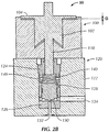
- the solenoid adjustment screw 144 may also be returned to a fully seated position (i.e ., turned inward to seat) to set the travel of the solenoid plunger 102. Moving the solenoid adjustment screw 144 inward to a seated position displaces hydraulic fluid in the second port 143 back against the stem portion 110 of the solenoid plunger 102, causing the solenoid plunger 102 to move upward and move the visual position indicator 104 slightly off (illustrated by gap "G”) the solenoid 100, as shown in Figure 2B .
- the visual position indicator 104 may be moved between 0.038 and 0.114 cm (0.015 and 0.045 of an inch) off the solenoid 100. In other embodiments, the distance G may be about 0.076 cm (0.030 of an inch).
- FIG. 3B other embodiments disclosed herein may include a solenoid adjustment/bleed screw 150 which incorporates both features of a bleed screw and a solenoid adjustment screw.
- the solenoid adjustment/bleed screw 150 is installed in a single port 152 in fluid communication with the fluid chamber 140.
- the solenoid adjustment/bleed screw 150 has a bleed channel 154 formed therein and, in addition, an O-ring located ahead of the bleed channel 154. Fluid may flow from the fluid chamber 140 through the bleed channel 154 when the adjustment/bleed screw 150 is positioned such that it is out of contact from seat 151 ( i.e ., unseated) and the O-ring 156 is not engaged in bore 157.
- the solenoid adjustment/bleed screw 150 may be turned outward four turns and unseated from seat 151, which moves the O-ring 156 out of contact with bore 157 in port 152 to allow fluid to escape through the bleed channel 154 from the fluid chamber 140. Once excess hydraulic fluid is removed from the fluid chamber 140, the solenoid adjustment/bleed screw 150 may then be turned inward two turns, which moves O-ring 156 back into sealing contact with bore 157 in port 152 so that hydraulic fluid is locked in the fluid chamber 140. Finally, the solenoid adjustment/bleed screw 150 may be turned in an additional two turns to fully seat the solenoid adjustment/bleed screw 150 on the seat 151.
- the fully seated solenoid adjustment/bleed screw 150 displaces hydraulic fluid in the fluid chamber 140 to move the visual indicator 104 ( Figure 2B ) off the solenoid 100.
- the number of turns of the solenoid adjustment/bleed screw 150 may be varied and still accomplish both the bleed and solenoid adjustment functions.
- force provided by the solenoid 100 may be transferred through the hydraulic fluid and multiplied against a surface of the valve member 128 exposed to the fluid chamber 140.
- the force multiplication is accomplished by the surface area differences between the stem portion 110 of the solenoid plunger 102 and the valve member 128.
- the valve member 128 has a surface area exposed to the fluid chamber 140 that is larger than a surface area of the stem portion 110 exposed to the fluid chamber 140. Therefore, a force multiplying effect is created between the stem portion 110 of the solenoid plunger 102 and the valve member 128 surfaces exposed to the fluid chamber 140.
- a surface area of the stem portion 110 exposed to the fluid chamber 140 may be one-fourth a surface area of the valve member 128 exposed to the fluid chamber, which provides a 4:1 force multiplying ratio between the surfaces.
- a 4:1 force multiplying ratio a force generated by the solenoid actuator 100 provides a force that is approximately 4 times greater between the valve member 128 and the valve seat 130.
- a 4:1 force multiplying ratio is illustrated as an example, one of ordinary skill in the art will appreciate that other force multiplying ratios between surface areas of the stem portion 110 and the valve member 128 exposed to the fluid chamber 140 may be used depending on the application and the force multiplying effect desired.
- a 2:1 force multiplying ratio or greater may be used in accordance with one or more embodiments disclosed herein. In other embodiments, a 1.25:1 force multiplying ratio or greater may be used.
- valve member 128 is maintained in the closed position against the valve seat 130 while filling the fluid chamber 140 with hydraulic fluid.
- the fluid chamber 140 is filled with hydraulic fluid through a bore in the upper cage 124 and the solenoid 100 is then coupled to the valve body 122.
- the bleed screw 142 and solenoid adjustment screw 144 are unseated (e.g., turned outward) as the solenoid 100 is coupled to the valve body 122 to allow excess hydraulic fluid in the fluid chamber 140 to be relieved through the bleed screw 142 ( Figure 3A ).
- the visual indicator 104 will sit flush on the solenoid 100 when all excess hydraulic fluid is out.
- the bleed screw 142 is then turned inward and returned to a fully seated position to lock hydraulic fluid in the fluid chamber 140.
- the solenoid adjustment screw 144 is turned inward to a fully seated position, which causes the visual indicator 104 to lift off the solenoid 100 a distance G ( Figure 2B ) due to displacement of the hydraulic fluid locked in the fluid chamber 140.
- Figure 2B represents the solenoid actuated valve assembly 50 in a final position after assembly.
- the solenoid 100 may be energized to cause the solenoid plunger 102 to provide a force against the hydraulic fluid in the fluid chamber 140.
- the force is transferred through the hydraulic fluid in the fluid chamber 140 and against the valve member 128.
- the force applied against the valve member 128 is multiplied according to the force multiplying ratio provided between surface areas of the solenoid plunger 102 and valve member 128 exposed to the fluid chamber 140.
- the solenoid 100 is energized, the valve member 128 will remain seated against the valve seat 130 and inlet port 132 will remain closed to prevent fluid communication between the fluid inlet 132 and outlet 134.
- the solenoid actuated valve assembly 50 may be closed against fluid pressures present in the inlet port 132 of up to 138 MPa (20,000 psi).
- the solenoid 100 may be deenergized. With no downward force provided from the solenoid 100, the pressure in the inlet port 132 forces the valve member 128 upward to allow fluid flow from the inlet port 132 to the outlet port 134.
- the solenoid plunger 102 is forced upward by a distance which corresponds to the force multiplying ratio. For example, for a 4:1 force multiplying ratio, the solenoid plunger 102 is forced upward by a distances that is four times greater than the travel of the valve member 128 in the lower cage 126. Upward movement of the visual indicator 104 gives a positive indication that the valve 120 is open.
- the valve 120 may be opened and closed by alternately energizing and de-energizing the solenoid 100.
- embodiments of the present disclosure provide a compact solenoid actuated valve assembly that is capable of closing against very high fluid pressure without requiring larger, more complex pneumatic or hydraulic actuator systems.
- the size, weight, and complexity of the solenoid actuated valve is reduced and requires less assembly time.
- the volume of hydraulic fluid in the fluid chamber of the valve rather than its pressure, retains the valve in a closed position, a high pressure fluid source is not required to operate the valve.
- response time of the valve is reduced because a high volume of fluid is no longer required to operate the actuator.
- the valve member due to the force multiplying ratios provided between the valve member and the solenoid plunger, the valve itself does not need to generate sufficient force to counterbalance high pressures present in the fluid inlet. Therefore, the valve member can be relatively small and compact. Moreover, costs to the end user are decreased due to the simplicity of the actuator and because no separate pneumatic or hydraulic supply lines are required to operate the valve. Overall, the one or more embodiments disclosed herein provide a more compact, less expensive, more reliable solenoid actuated valve assembly capable of operating against pressures of up to about 138 MPa (20,000 psi), or higher.
Landscapes
- Engineering & Computer Science (AREA)
- General Engineering & Computer Science (AREA)
- Mechanical Engineering (AREA)
- Magnetically Actuated Valves (AREA)
Claims (14)
- Elektromagnetisch betätigbare Ventilbaugruppe (50), die Folgendes umfasst:einen Ventilkörper (122) mit:einem Fluideingang (132) und Fluidausgang (134);einem im Ventilkörper (122) befindlichen Ventilglied (128), wobei eine Position des Ventilglieds (128) einen Fluidstrom zwischen dem Fluideingang (132) und Fluidausgang (134) steuert;einer Fluidkammer (140) über dem Ventilglied (128), wobei die Fluidkammer (140) fluidisch vom Fluideingang (132) und Ausgang (134) isoliert ist;einen mit dem Ventilkörper (122) gekoppelten Magnetantrieb (100) mit:einem Magnetkolben (102) nahe der Fluidkammer (140);wobei ein Kraftverstärkungsverhältnis eines gegenüber der Fluidkammer (140) ausgesetzten Oberflächenbereichs des Ventilglieds (128) zu einem gegenüber der Fluidkammer (140) ausgesetzten Oberflächenbereich des Magnetkolbens (102) mindestens 1,5:1 beträgt,dadurch gekennzeichnet, dass die elektromagnetisch betätigbare Ventilbaugruppe (50) weiterhin Folgendes umfasst:eine in einem ersten Anschluss (141) angeordnete Entlüftungsschraube (142) in Fluidverbindung mit der Fluidkammer (140), wobei die Entlüftungsschraube (142) einen Entlüftungskanal (146) dadurch umfasst; undeine in einem zweiten Anschluss (143) angeordnete Magneteinstellschraube (144) in Fluidverbindung mit der Fluidkammer (140).
- Elektromagnetisch betätigbare Ventilbaugruppe (50) nach Anspruch 1, die außerdem einen im Ventilkörper (122) angeordneten unteren Käfig (126) umfasst, in welchem das Ventilglied (128) gleitet.
- Elektromagnetisch betätigbare Ventilbaugruppe (50) nach Anspruch 2, wobei der untere Käfig (126) einen Ventilsitz (130) umfasst, der das Ventilglied (128) berührt.
- Elektromagnetisch betätigbare Ventilbaugruppe (50) nach Anspruch 1, die außerdem einen über der Fluidkammer (140) positionierten oberen Käfig (124) umfasst.
- Elektromagnetisch betätigbare Ventilbaugruppe (50) nach Anspruch 4, wobei der obere Käfig (124) einen oder mehrere Anschlüsse (149) umfasst, die über dessen Umfang verteilt sind und an eine Ringnut (148) des Ventilkörpers (122) angrenzend positioniert sind.
- Elektromagnetisch betätigbare Ventilbaugruppe (50) nach Anspruch 1, die weiterhin Folgendes umfasst:einen optischen Anzeiger (104) an einem Ende des Magnetkolbens (102),wobei die Magneteinstellschraube (144) so konfiguriert ist, dass sie den optischen Anzeiger (104) in einer Entfernung von zwischen ungefähr 0,038 und 0,114 cm (0,015 und 0,045 eines Zolls) zum Solenoid einstellt.
- Elektromagnetisch betätigbare Ventilbaugruppe (50) nach Anspruch 1, wobei die Magneteinstellschraube (144) des Weiteren einen O-Ring umfasst.
- Elektromagnetisch betätigbare Ventilbaugruppe (50) nach Anspruch 1, die außerdem einen Ventilsitz (130) im Ventilkörper (122) umfasst, welcher das Ventilglied (128) berührt.
- Elektromagnetisch betätigbare Ventilbaugruppe (50) nach Anspruch 1, die weiterhin eine Feder (136) in der Fluidkammer (140) umfasst, die das Ventilglied (128) in einer ersten Richtung vorspannt.
- Verfahren zum Zusammenbau eines elektromagnetisch betätigbaren Ventils (50), wobei das Verfahren Folgendes umfasst:Bereitstellung eines Ventilkörpers (122) umfassend:einen Fluideingang (132) und Fluidausgang (134);ein im Ventilkörper (122) angeordnetes Ventilglied (128), wobei eine Position des Ventilglieds (128) einen Fluidstrom zwischen dem Fluideingang (132) und Fluidausgang (134) steuert; undeine Fluidkammer (140) über dem Ventilglied (128), wobei die Fluidkammer (140) fluidisch vom Fluideingang (132) und Ausgang (134) isoliert ist;Bereitstellung eines Magnetantriebs (100) mit:einem Magnetkolben (102);Positionierung des Ventilglieds (128) in einer geschlossenen Position;Füllen der Fluidkammer (140) mit Hydraulikfluid; undAnkopplung des Magnetantriebs (100) an den Ventilkörper (122), wobei ein Schaftabschnitt (110) des Magnetkolbens (102) nahe der Fluidkammer (140) positioniert wird;dadurch gekennzeichnet, dass das Verfahren weiterhin Folgendes umfasst:Ablassen von überschüssigem Hydraulikfluid aus der Fluidkammer (140) durch den Entlüftungsschraubenanschluss (141) im Ventilkörper (122); sowie Anpassen einer Position des Magnetkolbens (102) mit einer Magneteinstellschraube (144);wobei die Magneteinstellschraube (144) in einem Anschluss (143) in Fluidverbindung mit der Fluidkammer (140) angeordnet ist;die Magneteinstellschraube (144) ermöglicht, dass das in der Fluidkammer (140) eingeschlossene Hydraulikfluid verdrängt wird, sodass der Magnetkolben (102) bewegt werden kann.
- Verfahren nach Anspruch 10, welches weiterhin umfasst, dass ein optischer Anzeiger (104) an einem Ende des Magnetkolbens (102) in einer Entfernung von zwischen ungefähr 0,038 und 0,114 cm (0,015 und 0,045 eines Zolls) vom Magnetantrieb (100) positioniert wird.
- Verfahren zur Verwendung eines elektromagnetisch betätigbaren Ventils (50), wobei das Verfahren Folgendes umfasst:Bereitstellen des elektromagnetisch betätigbaren Ventils (50) umfassend:einen Ventilkörper (122) umfassend:einen Fluideingang (132) und Fluidausgang (134);ein im Ventilkörper (122) angeordnetes Ventilglied (128), wobei eine Position des Ventilglieds (128) einen Fluidstrom zwischen dem Fluideingang (132) und Fluidausgang (134) steuert; und eine Fluidkammer (140), die über dem Ventilglied (128) angeordnet und mit Hydraulikfluid gefüllt ist, wobei die Fluidkammer (140) vom Fluideingang (132) und Ausgang (134) fluidisch isoliert ist; und einen mit dem Ventilkörper (122) gekoppelten Magnetantrieb (100) umfassend:einen Magnetkolben (102) nahe der Fluidkammer (140);dadurch gekennzeichnet, dass das Verfahren weiterhin Folgendes umfasst:Ablassen von überschüssigem Hydraulikfluid aus der Fluidkammer (140) durch den Entlüftungsschraubenanschluss (141) im Ventilkörper (122); sowie Aufbringen einer verstärken Kraft gegen das Ventilglied (128),wobei die verstärkte Kraft einem Kraftverstärkungsverhältnis eines gegenüber der Fluidkammer (140) ausgesetzten Oberflächenbereichs des Ventilglieds (128) zu einem gegenüber der Fluidkammer (140) ausgesetzten Oberflächenbereich des Magnetkolbens (102) entspricht;eine Magneteinstellschraube (144) in einem Anschluss (143) in Fluidverbindung mit der Fluidkammer (140) angeordnet ist; unddie Magneteinstellschraube (144) ermöglicht, dass das in der Fluidkammer (140) eingeschlossene Hydraulikfluid verdrängt wird, sodass der Magnetkolben (102) bewegt werden kann.
- Verfahren nach Anspruch 12, wobei das Kraftverstärkungsverhältnis mindestens 1,5:1 beträgt.
- Verfahren nach Anspruch 12, wobei das Aufbringen einer verstärkten Kraft des Weiteren das Einschalten des Magnetantriebs (100) umfasst.
Applications Claiming Priority (1)
| Application Number | Priority Date | Filing Date | Title |
|---|---|---|---|
| PCT/US2012/022208 WO2013112128A1 (en) | 2012-01-23 | 2012-01-23 | Force multiplying solenoid valve |
Publications (2)
| Publication Number | Publication Date |
|---|---|
| EP2807413A1 EP2807413A1 (de) | 2014-12-03 |
| EP2807413B1 true EP2807413B1 (de) | 2017-05-03 |
Family
ID=45563578
Family Applications (1)
| Application Number | Title | Priority Date | Filing Date |
|---|---|---|---|
| EP12702699.5A Not-in-force EP2807413B1 (de) | 2012-01-23 | 2012-01-23 | Kraftmultiplizierendes magnetventil |
Country Status (5)
| Country | Link |
|---|---|
| US (1) | US9371934B2 (de) |
| EP (1) | EP2807413B1 (de) |
| CA (1) | CA2862415C (de) |
| SG (1) | SG11201404346QA (de) |
| WO (1) | WO2013112128A1 (de) |
Families Citing this family (2)
| Publication number | Priority date | Publication date | Assignee | Title |
|---|---|---|---|---|
| CN109751417B (zh) * | 2017-11-01 | 2020-03-06 | 浙江三花制冷集团有限公司 | 一种先导式电磁阀 |
| US12102969B2 (en) * | 2021-02-03 | 2024-10-01 | GAT8 CFV Solutions, INC. | Valve device |
Family Cites Families (16)
| Publication number | Priority date | Publication date | Assignee | Title |
|---|---|---|---|---|
| US1822668A (en) * | 1927-02-23 | 1931-09-08 | O F Jordan Co | Electromagnetic valve |
| US3223112A (en) * | 1960-04-26 | 1965-12-14 | Clifford L Ashbrook | Automatic control system for a piston operated valve |
| US4335743A (en) * | 1980-03-27 | 1982-06-22 | Leon Jones | Milking machine system, and pressure regulator incorporated therein |
| US4385546A (en) * | 1981-10-13 | 1983-05-31 | Lee Richard J | Cartridge reloading dies |
| US4993456A (en) * | 1982-03-02 | 1991-02-19 | Akos Sule | Pinch valve assembly |
| US4603832A (en) * | 1985-06-07 | 1986-08-05 | Evolutionary Concepts, Inc. | Solenoid actuator with bleed screw |
| US4932439A (en) * | 1988-12-12 | 1990-06-12 | Colt Industries Inc. | Solenoid actuated three-way valve |
| US5204652A (en) * | 1990-11-20 | 1993-04-20 | National Irrigation Specialists, Inc. | Adjustable bleed system for a universal solenoid for fluid control valves |
| US5074326A (en) * | 1990-11-20 | 1991-12-24 | National Irrigation Specialists | Adjustable plunger system for a universal solenoid for fluid control valves |
| US5548263A (en) * | 1992-10-05 | 1996-08-20 | Aura Systems, Inc. | Electromagnetically actuated valve |
| DE19843534A1 (de) * | 1998-09-23 | 2000-03-30 | Bosch Gmbh Robert | Brennstoffeinspritzventil |
| DE19950224A1 (de) | 1999-10-19 | 2001-04-26 | Bosch Gmbh Robert | Doppelschaltendes Steuerventil für einen Injektor eines Kraftstoffeinspritzsystems für Brennkraftmaschinen mit kugelförmigem Stellglied |
| JP2003232464A (ja) * | 2002-02-06 | 2003-08-22 | Komatsu Ltd | 電磁駆動弁 |
| DE10240523A1 (de) | 2002-09-03 | 2004-03-11 | Ufermann, Rüdiger | Freie Elektrohydraulische-Ventilsteuerung für Brennkraftmaschinen |
| JP2005140223A (ja) * | 2003-11-06 | 2005-06-02 | Nippon M K S Kk | 制御弁 |
| JP5150425B2 (ja) * | 2008-09-11 | 2013-02-20 | 川崎重工業株式会社 | 油浸型ソレノイドの調整ネジ構造及びそれを備える油浸型ソレノイド |
-
2012
- 2012-01-23 EP EP12702699.5A patent/EP2807413B1/de not_active Not-in-force
- 2012-01-23 CA CA2862415A patent/CA2862415C/en active Active
- 2012-01-23 WO PCT/US2012/022208 patent/WO2013112128A1/en not_active Ceased
- 2012-01-23 US US14/374,166 patent/US9371934B2/en active Active
- 2012-01-23 SG SG11201404346QA patent/SG11201404346QA/en unknown
Also Published As
| Publication number | Publication date |
|---|---|
| WO2013112128A1 (en) | 2013-08-01 |
| CA2862415A1 (en) | 2013-08-01 |
| EP2807413A1 (de) | 2014-12-03 |
| US9371934B2 (en) | 2016-06-21 |
| SG11201404346QA (en) | 2014-10-30 |
| CA2862415C (en) | 2016-10-04 |
| US20150034187A1 (en) | 2015-02-05 |
Similar Documents
| Publication | Publication Date | Title |
|---|---|---|
| US9057448B2 (en) | Internal relief valve for a valve actuator | |
| CN102203479B (zh) | 阀门组件 | |
| EP2689141B1 (de) | Vorgesteuertes elektroproportionalsitzventil mit druckausgleich | |
| GB2177458A (en) | Dual stage hydraulic actuator | |
| US3324889A (en) | Solenoid-actuated valve | |
| US6588724B2 (en) | On-off valves for high pressure fluids | |
| US9404513B2 (en) | Servo valve | |
| US6701959B1 (en) | High flow rate balanced poppet valve | |
| US20100320407A1 (en) | Fluid-biased hydraulic control valve | |
| KR20130014555A (ko) | 연료 공급용 압력 조절기 및 그 압력 조절기로 구성된 조절 유닛을 포함하는 연료 공급 시스템 | |
| JP2004069069A (ja) | ソレノイド作動圧力制御弁 | |
| CN107850233A (zh) | 电磁阀 | |
| CA2862415C (en) | Force multiplying solenoid valve | |
| US9476514B2 (en) | Valve, in particular a pressure regulating valve or pressure limiting valve | |
| JP6592300B2 (ja) | バイパス通路付きチェック弁を備えるソレノイドバルブ | |
| US8622080B2 (en) | Pressure reducer | |
| EP1486712B1 (de) | Dreiwegeventil | |
| CN113775764A (zh) | 一种大流量无泄漏卸荷阀 | |
| JP6088608B1 (ja) | 一方向流制御弁 | |
| WO2019115828A1 (en) | Pilot controlled electromagnetic valve with auxiliary piston | |
| EP4244511B1 (de) | Ventilsystem | |
| JP3626634B2 (ja) | 弁装置 | |
| RU1836600C (ru) | Электромагнитный клапан | |
| JP2024130293A (ja) | リリーフ弁 | |
| JP2017053377A (ja) | 複合弁及びそれを用いたソレノイドバルブ |
Legal Events
| Date | Code | Title | Description |
|---|---|---|---|
| PUAI | Public reference made under article 153(3) epc to a published international application that has entered the european phase |
Free format text: ORIGINAL CODE: 0009012 |
|
| 17P | Request for examination filed |
Effective date: 20140814 |
|
| AK | Designated contracting states |
Kind code of ref document: A1 Designated state(s): AL AT BE BG CH CY CZ DE DK EE ES FI FR GB GR HR HU IE IS IT LI LT LU LV MC MK MT NL NO PL PT RO RS SE SI SK SM TR |
|
| DAX | Request for extension of the european patent (deleted) | ||
| 17Q | First examination report despatched |
Effective date: 20160616 |
|
| GRAP | Despatch of communication of intention to grant a patent |
Free format text: ORIGINAL CODE: EPIDOSNIGR1 |
|
| STAA | Information on the status of an ep patent application or granted ep patent |
Free format text: STATUS: GRANT OF PATENT IS INTENDED |
|
| INTG | Intention to grant announced |
Effective date: 20161110 |
|
| GRAS | Grant fee paid |
Free format text: ORIGINAL CODE: EPIDOSNIGR3 |
|
| GRAA | (expected) grant |
Free format text: ORIGINAL CODE: 0009210 |
|
| STAA | Information on the status of an ep patent application or granted ep patent |
Free format text: STATUS: THE PATENT HAS BEEN GRANTED |
|
| AK | Designated contracting states |
Kind code of ref document: B1 Designated state(s): AL AT BE BG CH CY CZ DE DK EE ES FI FR GB GR HR HU IE IS IT LI LT LU LV MC MK MT NL NO PL PT RO RS SE SI SK SM TR |
|
| REG | Reference to a national code |
Ref country code: GB Ref legal event code: FG4D |
|
| REG | Reference to a national code |
Ref country code: AT Ref legal event code: REF Ref document number: 890375 Country of ref document: AT Kind code of ref document: T Effective date: 20170515 Ref country code: CH Ref legal event code: EP |
|
| REG | Reference to a national code |
Ref country code: IE Ref legal event code: FG4D |
|
| REG | Reference to a national code |
Ref country code: DE Ref legal event code: R096 Ref document number: 602012031872 Country of ref document: DE |
|
| REG | Reference to a national code |
Ref country code: NL Ref legal event code: FP |
|
| REG | Reference to a national code |
Ref country code: NO Ref legal event code: T2 Effective date: 20170503 |
|
| REG | Reference to a national code |
Ref country code: AT Ref legal event code: MK05 Ref document number: 890375 Country of ref document: AT Kind code of ref document: T Effective date: 20170503 |
|
| REG | Reference to a national code |
Ref country code: LT Ref legal event code: MG4D |
|
| PG25 | Lapsed in a contracting state [announced via postgrant information from national office to epo] |
Ref country code: HR Free format text: LAPSE BECAUSE OF FAILURE TO SUBMIT A TRANSLATION OF THE DESCRIPTION OR TO PAY THE FEE WITHIN THE PRESCRIBED TIME-LIMIT Effective date: 20170503 Ref country code: FI Free format text: LAPSE BECAUSE OF FAILURE TO SUBMIT A TRANSLATION OF THE DESCRIPTION OR TO PAY THE FEE WITHIN THE PRESCRIBED TIME-LIMIT Effective date: 20170503 Ref country code: AT Free format text: LAPSE BECAUSE OF FAILURE TO SUBMIT A TRANSLATION OF THE DESCRIPTION OR TO PAY THE FEE WITHIN THE PRESCRIBED TIME-LIMIT Effective date: 20170503 Ref country code: ES Free format text: LAPSE BECAUSE OF FAILURE TO SUBMIT A TRANSLATION OF THE DESCRIPTION OR TO PAY THE FEE WITHIN THE PRESCRIBED TIME-LIMIT Effective date: 20170503 Ref country code: GR Free format text: LAPSE BECAUSE OF FAILURE TO SUBMIT A TRANSLATION OF THE DESCRIPTION OR TO PAY THE FEE WITHIN THE PRESCRIBED TIME-LIMIT Effective date: 20170804 Ref country code: LT Free format text: LAPSE BECAUSE OF FAILURE TO SUBMIT A TRANSLATION OF THE DESCRIPTION OR TO PAY THE FEE WITHIN THE PRESCRIBED TIME-LIMIT Effective date: 20170503 |
|
| PG25 | Lapsed in a contracting state [announced via postgrant information from national office to epo] |
Ref country code: RS Free format text: LAPSE BECAUSE OF FAILURE TO SUBMIT A TRANSLATION OF THE DESCRIPTION OR TO PAY THE FEE WITHIN THE PRESCRIBED TIME-LIMIT Effective date: 20170503 Ref country code: SE Free format text: LAPSE BECAUSE OF FAILURE TO SUBMIT A TRANSLATION OF THE DESCRIPTION OR TO PAY THE FEE WITHIN THE PRESCRIBED TIME-LIMIT Effective date: 20170503 Ref country code: PL Free format text: LAPSE BECAUSE OF FAILURE TO SUBMIT A TRANSLATION OF THE DESCRIPTION OR TO PAY THE FEE WITHIN THE PRESCRIBED TIME-LIMIT Effective date: 20170503 Ref country code: BG Free format text: LAPSE BECAUSE OF FAILURE TO SUBMIT A TRANSLATION OF THE DESCRIPTION OR TO PAY THE FEE WITHIN THE PRESCRIBED TIME-LIMIT Effective date: 20170803 Ref country code: IS Free format text: LAPSE BECAUSE OF FAILURE TO SUBMIT A TRANSLATION OF THE DESCRIPTION OR TO PAY THE FEE WITHIN THE PRESCRIBED TIME-LIMIT Effective date: 20170903 Ref country code: LV Free format text: LAPSE BECAUSE OF FAILURE TO SUBMIT A TRANSLATION OF THE DESCRIPTION OR TO PAY THE FEE WITHIN THE PRESCRIBED TIME-LIMIT Effective date: 20170503 |
|
| PG25 | Lapsed in a contracting state [announced via postgrant information from national office to epo] |
Ref country code: CZ Free format text: LAPSE BECAUSE OF FAILURE TO SUBMIT A TRANSLATION OF THE DESCRIPTION OR TO PAY THE FEE WITHIN THE PRESCRIBED TIME-LIMIT Effective date: 20170503 Ref country code: DK Free format text: LAPSE BECAUSE OF FAILURE TO SUBMIT A TRANSLATION OF THE DESCRIPTION OR TO PAY THE FEE WITHIN THE PRESCRIBED TIME-LIMIT Effective date: 20170503 Ref country code: RO Free format text: LAPSE BECAUSE OF FAILURE TO SUBMIT A TRANSLATION OF THE DESCRIPTION OR TO PAY THE FEE WITHIN THE PRESCRIBED TIME-LIMIT Effective date: 20170503 Ref country code: EE Free format text: LAPSE BECAUSE OF FAILURE TO SUBMIT A TRANSLATION OF THE DESCRIPTION OR TO PAY THE FEE WITHIN THE PRESCRIBED TIME-LIMIT Effective date: 20170503 Ref country code: SK Free format text: LAPSE BECAUSE OF FAILURE TO SUBMIT A TRANSLATION OF THE DESCRIPTION OR TO PAY THE FEE WITHIN THE PRESCRIBED TIME-LIMIT Effective date: 20170503 |
|
| REG | Reference to a national code |
Ref country code: DE Ref legal event code: R097 Ref document number: 602012031872 Country of ref document: DE |
|
| PG25 | Lapsed in a contracting state [announced via postgrant information from national office to epo] |
Ref country code: SM Free format text: LAPSE BECAUSE OF FAILURE TO SUBMIT A TRANSLATION OF THE DESCRIPTION OR TO PAY THE FEE WITHIN THE PRESCRIBED TIME-LIMIT Effective date: 20170503 Ref country code: IT Free format text: LAPSE BECAUSE OF FAILURE TO SUBMIT A TRANSLATION OF THE DESCRIPTION OR TO PAY THE FEE WITHIN THE PRESCRIBED TIME-LIMIT Effective date: 20170503 |
|
| PLBE | No opposition filed within time limit |
Free format text: ORIGINAL CODE: 0009261 |
|
| STAA | Information on the status of an ep patent application or granted ep patent |
Free format text: STATUS: NO OPPOSITION FILED WITHIN TIME LIMIT |
|
| 26N | No opposition filed |
Effective date: 20180206 |
|
| PG25 | Lapsed in a contracting state [announced via postgrant information from national office to epo] |
Ref country code: SI Free format text: LAPSE BECAUSE OF FAILURE TO SUBMIT A TRANSLATION OF THE DESCRIPTION OR TO PAY THE FEE WITHIN THE PRESCRIBED TIME-LIMIT Effective date: 20170503 |
|
| REG | Reference to a national code |
Ref country code: FR Ref legal event code: PLFP Year of fee payment: 7 |
|
| REG | Reference to a national code |
Ref country code: CH Ref legal event code: PL |
|
| PG25 | Lapsed in a contracting state [announced via postgrant information from national office to epo] |
Ref country code: LU Free format text: LAPSE BECAUSE OF NON-PAYMENT OF DUE FEES Effective date: 20180123 |
|
| REG | Reference to a national code |
Ref country code: IE Ref legal event code: MM4A |
|
| REG | Reference to a national code |
Ref country code: BE Ref legal event code: MM Effective date: 20180131 |
|
| PG25 | Lapsed in a contracting state [announced via postgrant information from national office to epo] |
Ref country code: BE Free format text: LAPSE BECAUSE OF NON-PAYMENT OF DUE FEES Effective date: 20180131 Ref country code: LI Free format text: LAPSE BECAUSE OF NON-PAYMENT OF DUE FEES Effective date: 20180131 Ref country code: CH Free format text: LAPSE BECAUSE OF NON-PAYMENT OF DUE FEES Effective date: 20180131 |
|
| PG25 | Lapsed in a contracting state [announced via postgrant information from national office to epo] |
Ref country code: IE Free format text: LAPSE BECAUSE OF NON-PAYMENT OF DUE FEES Effective date: 20180123 |
|
| PG25 | Lapsed in a contracting state [announced via postgrant information from national office to epo] |
Ref country code: MC Free format text: LAPSE BECAUSE OF FAILURE TO SUBMIT A TRANSLATION OF THE DESCRIPTION OR TO PAY THE FEE WITHIN THE PRESCRIBED TIME-LIMIT Effective date: 20170503 |
|
| PG25 | Lapsed in a contracting state [announced via postgrant information from national office to epo] |
Ref country code: MT Free format text: LAPSE BECAUSE OF NON-PAYMENT OF DUE FEES Effective date: 20180123 |
|
| PG25 | Lapsed in a contracting state [announced via postgrant information from national office to epo] |
Ref country code: TR Free format text: LAPSE BECAUSE OF FAILURE TO SUBMIT A TRANSLATION OF THE DESCRIPTION OR TO PAY THE FEE WITHIN THE PRESCRIBED TIME-LIMIT Effective date: 20170503 |
|
| PG25 | Lapsed in a contracting state [announced via postgrant information from national office to epo] |
Ref country code: HU Free format text: LAPSE BECAUSE OF FAILURE TO SUBMIT A TRANSLATION OF THE DESCRIPTION OR TO PAY THE FEE WITHIN THE PRESCRIBED TIME-LIMIT; INVALID AB INITIO Effective date: 20120123 Ref country code: PT Free format text: LAPSE BECAUSE OF FAILURE TO SUBMIT A TRANSLATION OF THE DESCRIPTION OR TO PAY THE FEE WITHIN THE PRESCRIBED TIME-LIMIT Effective date: 20170503 |
|
| PG25 | Lapsed in a contracting state [announced via postgrant information from national office to epo] |
Ref country code: MK Free format text: LAPSE BECAUSE OF NON-PAYMENT OF DUE FEES Effective date: 20170503 Ref country code: CY Free format text: LAPSE BECAUSE OF FAILURE TO SUBMIT A TRANSLATION OF THE DESCRIPTION OR TO PAY THE FEE WITHIN THE PRESCRIBED TIME-LIMIT Effective date: 20170503 |
|
| PG25 | Lapsed in a contracting state [announced via postgrant information from national office to epo] |
Ref country code: AL Free format text: LAPSE BECAUSE OF FAILURE TO SUBMIT A TRANSLATION OF THE DESCRIPTION OR TO PAY THE FEE WITHIN THE PRESCRIBED TIME-LIMIT Effective date: 20170503 |
|
| PGFP | Annual fee paid to national office [announced via postgrant information from national office to epo] |
Ref country code: NL Payment date: 20221220 Year of fee payment: 12 Ref country code: GB Payment date: 20221201 Year of fee payment: 12 Ref country code: FR Payment date: 20221208 Year of fee payment: 12 |
|
| PGFP | Annual fee paid to national office [announced via postgrant information from national office to epo] |
Ref country code: NO Payment date: 20230110 Year of fee payment: 12 |
|
| PGFP | Annual fee paid to national office [announced via postgrant information from national office to epo] |
Ref country code: DE Payment date: 20221130 Year of fee payment: 12 |
|
| REG | Reference to a national code |
Ref country code: DE Ref legal event code: R119 Ref document number: 602012031872 Country of ref document: DE |
|
| REG | Reference to a national code |
Ref country code: NL Ref legal event code: MM Effective date: 20240201 |
|
| GBPC | Gb: european patent ceased through non-payment of renewal fee |
Effective date: 20240123 |
|
| PG25 | Lapsed in a contracting state [announced via postgrant information from national office to epo] |
Ref country code: DE Free format text: LAPSE BECAUSE OF NON-PAYMENT OF DUE FEES Effective date: 20240801 |
|
| PG25 | Lapsed in a contracting state [announced via postgrant information from national office to epo] |
Ref country code: GB Free format text: LAPSE BECAUSE OF NON-PAYMENT OF DUE FEES Effective date: 20240123 |
|
| PG25 | Lapsed in a contracting state [announced via postgrant information from national office to epo] |
Ref country code: FR Free format text: LAPSE BECAUSE OF NON-PAYMENT OF DUE FEES Effective date: 20240131 |
|
| PG25 | Lapsed in a contracting state [announced via postgrant information from national office to epo] |
Ref country code: NL Free format text: LAPSE BECAUSE OF NON-PAYMENT OF DUE FEES Effective date: 20240201 |
|
| PG25 | Lapsed in a contracting state [announced via postgrant information from national office to epo] |
Ref country code: NO Free format text: LAPSE BECAUSE OF NON-PAYMENT OF DUE FEES Effective date: 20240131 Ref country code: NL Free format text: LAPSE BECAUSE OF NON-PAYMENT OF DUE FEES Effective date: 20240201 Ref country code: GB Free format text: LAPSE BECAUSE OF NON-PAYMENT OF DUE FEES Effective date: 20240123 Ref country code: FR Free format text: LAPSE BECAUSE OF NON-PAYMENT OF DUE FEES Effective date: 20240131 Ref country code: DE Free format text: LAPSE BECAUSE OF NON-PAYMENT OF DUE FEES Effective date: 20240801 |