EP2807499B1 - Circuit de commande et procédé d'amortissement actif d'un transducteur ultrasonore, et système de mesure par ultrasons - Google Patents
Circuit de commande et procédé d'amortissement actif d'un transducteur ultrasonore, et système de mesure par ultrasons Download PDFInfo
- Publication number
- EP2807499B1 EP2807499B1 EP12808723.6A EP12808723A EP2807499B1 EP 2807499 B1 EP2807499 B1 EP 2807499B1 EP 12808723 A EP12808723 A EP 12808723A EP 2807499 B1 EP2807499 B1 EP 2807499B1
- Authority
- EP
- European Patent Office
- Prior art keywords
- actuating
- circuit
- voltage
- ultrasonic transducer
- amplitude
- Prior art date
- Legal status (The legal status is an assumption and is not a legal conclusion. Google has not performed a legal analysis and makes no representation as to the accuracy of the status listed.)
- Not-in-force
Links
- 238000013016 damping Methods 0.000 title claims description 24
- 238000000034 method Methods 0.000 title claims description 11
- 239000003990 capacitor Substances 0.000 claims description 15
- 230000003247 decreasing effect Effects 0.000 claims description 6
- 230000005284 excitation Effects 0.000 claims description 5
- 238000002604 ultrasonography Methods 0.000 claims description 5
- 238000005259 measurement Methods 0.000 claims 2
- 238000010586 diagram Methods 0.000 description 11
- 239000012528 membrane Substances 0.000 description 10
- 230000010355 oscillation Effects 0.000 description 7
- 230000004913 activation Effects 0.000 description 6
- 238000001514 detection method Methods 0.000 description 3
- 230000005540 biological transmission Effects 0.000 description 2
- 230000001276 controlling effect Effects 0.000 description 2
- 230000000694 effects Effects 0.000 description 2
- 230000002349 favourable effect Effects 0.000 description 2
- 230000005855 radiation Effects 0.000 description 2
- 239000004065 semiconductor Substances 0.000 description 2
- 230000001360 synchronised effect Effects 0.000 description 2
- 230000002238 attenuated effect Effects 0.000 description 1
- 230000003111 delayed effect Effects 0.000 description 1
- 230000001419 dependent effect Effects 0.000 description 1
- 238000011161 development Methods 0.000 description 1
- 230000018109 developmental process Effects 0.000 description 1
- 230000008030 elimination Effects 0.000 description 1
- 238000003379 elimination reaction Methods 0.000 description 1
- 238000011156 evaluation Methods 0.000 description 1
- 239000006260 foam Substances 0.000 description 1
- 239000000463 material Substances 0.000 description 1
- 230000010363 phase shift Effects 0.000 description 1
- 238000013139 quantization Methods 0.000 description 1
- 230000001105 regulatory effect Effects 0.000 description 1
- 238000001228 spectrum Methods 0.000 description 1
Images



Classifications
-
- G—PHYSICS
- G01—MEASURING; TESTING
- G01S—RADIO DIRECTION-FINDING; RADIO NAVIGATION; DETERMINING DISTANCE OR VELOCITY BY USE OF RADIO WAVES; LOCATING OR PRESENCE-DETECTING BY USE OF THE REFLECTION OR RERADIATION OF RADIO WAVES; ANALOGOUS ARRANGEMENTS USING OTHER WAVES
- G01S7/00—Details of systems according to groups G01S13/00, G01S15/00, G01S17/00
- G01S7/52—Details of systems according to groups G01S13/00, G01S15/00, G01S17/00 of systems according to group G01S15/00
- G01S7/523—Details of pulse systems
- G01S7/524—Transmitters
-
- B—PERFORMING OPERATIONS; TRANSPORTING
- B06—GENERATING OR TRANSMITTING MECHANICAL VIBRATIONS IN GENERAL
- B06B—METHODS OR APPARATUS FOR GENERATING OR TRANSMITTING MECHANICAL VIBRATIONS OF INFRASONIC, SONIC, OR ULTRASONIC FREQUENCY, e.g. FOR PERFORMING MECHANICAL WORK IN GENERAL
- B06B1/00—Methods or apparatus for generating mechanical vibrations of infrasonic, sonic, or ultrasonic frequency
- B06B1/02—Methods or apparatus for generating mechanical vibrations of infrasonic, sonic, or ultrasonic frequency making use of electrical energy
- B06B1/0207—Driving circuits
- B06B1/0215—Driving circuits for generating pulses, e.g. bursts of oscillations, envelopes
-
- B—PERFORMING OPERATIONS; TRANSPORTING
- B06—GENERATING OR TRANSMITTING MECHANICAL VIBRATIONS IN GENERAL
- B06B—METHODS OR APPARATUS FOR GENERATING OR TRANSMITTING MECHANICAL VIBRATIONS OF INFRASONIC, SONIC, OR ULTRASONIC FREQUENCY, e.g. FOR PERFORMING MECHANICAL WORK IN GENERAL
- B06B2201/00—Indexing scheme associated with B06B1/0207 for details covered by B06B1/0207 but not provided for in any of its subgroups
- B06B2201/30—Indexing scheme associated with B06B1/0207 for details covered by B06B1/0207 but not provided for in any of its subgroups with electronic damping
Definitions
- the invention relates to a drive circuit for driving an ultrasonic transducer.
- the invention relates to a drive circuit having an input for a supply voltage, an input for receiving a drive pulse, an envelope generator, and an output for outputting voltage pulses to the ultrasonic transducer to be controlled.
- the invention relates to an associated method for damping a transducer element of an ultrasonic transducer by active counter-control with electrical drive pulses, and a measuring system for detecting objects by means of ultrasound.
- acoustic environment detection of vehicles currently systems are usually used in the ultrasonic range, preferably measuring pulse. In this case, typically every 10 ms to 300 ms via an electro-acoustic transducer acoustic pulses emitted at about 50 kHz. From the pulse transit time to the transmitting and / or non-transmitting transducers, the object distance in space is inferred.
- a piezo-diaphragm is set in vibration by means of electrical pulses. This vibration is used for sound radiation.
- the membrane To be able to, the membrane must be brought as soon as possible after the sound radiation to a halt. The sound reflected on an object then hits the stationary membrane and vibrates it again.
- the vibration of the membrane produced by the original excitation decays only very slowly, so that this vibration can be superimposed on the reflected signal.
- the oscillation can also be selectively actively damped by counter-activation in order to bring the membrane back to a standstill.
- the in DE 10 2009 027 221 A1 shown method after the first sending the control of the ultrasonic transducer switched high impedance, so that the membrane can swing freely. Thereafter, the converter for active damping is driven out of phase or out of phase. After a few periods, the control must be synchronized again with the resonant circuit of the ultrasonic transducer to measure the vibration state of the ultrasonic sensor or its independent vibration. For this purpose, the control must again be temporarily switched to high impedance.
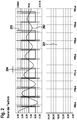
- FIG. 1 By way of example, the principle of such an active damping method is shown by means of a voltage-time and current-time diagram. It is in the upper part of FIG. 1 the voltage waveform of a drive voltage 101 is shown, which runs in accordance with a square wave signal with a temporarily constant amplitude. In comparison, the lower part of FIG. 1 the simulated current 102 in a controlled according to the above drive voltage oscillator, for example, an ultrasonic sensor. Like from the FIG. 1 can be seen, in the example shown, the ultrasonic sensor is first excited with a square wave constant amplitude of the order of 50 V and thereby finally reaches an oscillator AC 102 of more than 20 mA.
- the ultrasonic sensor is first excited with a square wave constant amplitude of the order of 50 V and thereby finally reaches an oscillator AC 102 of more than 20 mA.
- the converter After a short drive pause, the converter is driven again with the same amplitude, but phase-shifted. This dampens the membrane vibration. Furthermore, after the damping drive cycle, which consists of a plurality of pulses, the current oscillation of the sensor is newly detected and synchronized 103. In the next control is then again driven in phase opposition to the natural oscillation of the ultrasonic sensor. The synchronization is necessary in this case, since a detection of the natural vibration of the sensor during a control is usually not possible. Thus, several drive cycles of different amplitude are performed to bring the membrane to a standstill. As in FIG. 1 shown by way of example, 3 damping cycles 104, 105, 106 are traversed in the example. The synchronization 103 between the cycles 104, 105, 106 requires time, which is no longer available for damping in a row.
- FIG. 2 On the basis of in FIG. 2 The illustration shows the above-mentioned effect, namely that vibration of the transducer can be detected only delayed. This makes it difficult to make the synchronization fast enough.
- a drive signal 201 is shown with decreasing amplitude, and in the upper part of the current 202 through the inductance of the transducer and the resulting output signal 203 of the signal amplifier are shown.
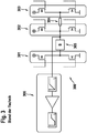
- FIG. 3 For example, one example of such a step-wise multi-half-bridge arrangement 300 is shown.
- the excitation of the ultrasonic transducer 305 and the initial attenuation with a connected to the full operating voltage, consisting of two Mosfet transistors half bridge 301.
- a smaller amplitude is then generated with a further half stage 302, which is either connected to a lower supply voltage, or with a half stage 303, which is connected via a resistor 304 to the transducer 305.
- each voltage stage available for attenuation requires a separate half-bridge 301, 302, 303.
- a measuring amplifier 306 for the output signal of the ultrasonic transducer 305 is shown.
- FIG. 4 shows the equivalent circuit diagram of a typical ultrasonic transducer according to the prior art with exemplary numerical values for the occurring inductances, capacitances, and ohmic resistances. with capacitances As part of the attenuation this current should be reduced by L1 to a few ⁇ A up to nA.
- a drive circuit for driving an ultrasonic transducer is off US 2010/113935 A1 known.
- a method for damping a transducer element of an ultrasonic transducer by active counter-control with electrical drive pulses is off DE 195 48 161 C1 known.
- a drive circuit for driving an ultrasonic transducer has an input for a supply voltage, an input for receiving a drive pulse, and an output for outputting voltage pulses to the ultrasonic transducer.
- the circuit arrangement has a first circuit block for generating a first voltage and a second circuit block for generating a second voltage, which are coupled to one another during operation of the circuit arrangement to supply the ultrasonic transducer alternately via the first circuit block and via the second circuit block in accordance with the received drive pulse, the time mean value of the voltage pulses output to the ultrasonic transducer is always kept at the value of half the supply voltage.
- the ultrasonic transducer in a method for damping a resonant transducer element of an ultrasonic transducer for active countersteering, the ultrasonic transducer is driven by electrical drive pulses having a temporally monotonically decreasing drive amplitude, the time average of the drive pulses always being kept at the value of half the supply voltage of the drive circuit used.
- a measuring system for detecting objects by means of ultrasound which has an ultrasonic sensor with a resonant transducer element and the drive circuit according to the invention.
- the measuring system is set up to carry out an active damping of the resonant transducer element in such a manner after an excitation made to emit ultrasonic waves the amplitude of the voltage pulses output to the ultrasonic sensor during the active damping is always smaller than the amplitude of the sensor signal of the ultrasonic sensor.
- a solution for use in the control of ultrasonic transducers in ultrasonic transducer having measuring systems, on the one hand, can be exploited a wide dynamic range.
- the full operating voltage can be used for a control, but in many stages, continuously and safely guided to a defined average.
- the shape of the envelope may optionally also be adjusted such that it operates with a lower start amplitude.
- the invention can be used with conventional pulse generators, wherein the driving frequency is adjusted depending on the application. The same applies, as already indicated, for the supply voltage. If required, it is possible to react to changed requirements with regard to the signal amplitude by changing the time activation of the lowering of the activation.
- the invention operates ratiometrically, ie by the same value by which the voltage in one of the voltage blocks increases, the voltage in the other voltage block is reduced. Because of the symmetrical about the average control is particularly ensured that no half wave output voltage pulses too large a swing of the voltage, which is particularly advantageous if the driven ultrasonic transducer was attenuated in the course of active damping already small sensor signals.
- the amplitude of the counter-control can be regulated over a wide range.
- the counter-control is permanent, ie without pauses.
- the drive circuit has a push-pull stage or a half-bridge with a first transistor and a second transistor, which can be driven via the input for receiving a drive pulse, wherein the first transistor is connected to the the first circuit block is coupled and the second transistor is coupled to the second circuit block and wherein the output of the push-pull stage is coupled to the output for outputting voltage pulses to the sensor.
- the drive circuit further comprises a pulse generator provided for driving the push-pull stage, in particular a square-wave signal generator, an envelope circuit, and a microcontroller for controlling the drive circuit, wherein the envelope circuit comprises an RC element with a capacitor and one or more resistors for charging of the capacitor, so that the drive circuit is adapted to drive the ultrasonic transducer with voltage pulses whose envelope is determined by the charging curve of the capacitor and whose time average is always maintained at the value of half the supply voltage.
- a pulse generator provided for driving the push-pull stage, in particular a square-wave signal generator, an envelope circuit, and a microcontroller for controlling the drive circuit
- the envelope circuit comprises an RC element with a capacitor and one or more resistors for charging of the capacitor, so that the drive circuit is adapted to drive the ultrasonic transducer with voltage pulses whose envelope is determined by the charging curve of the capacitor and whose time average is always maintained at the value of half the supply voltage.
- the drive circuit comprises the pulse generator provided for driving the push-pull stage, in particular a square-wave signal generator, a microcontroller for controlling the drive circuit, and an envelope generator having a pulse generator Digital-to-analog converter on.
- the envelope generator can be implemented in the microcontroller, and according to a variant of this embodiment, the microcontroller can also be designed to control the first circuit block provided for generating a first voltage and the second circuit block provided for generating a second voltage.
- the drive circuit is further configured to generate and output the voltage pulses to the ultrasonic transducer such that a decrease in the amplitude is distributed to both half-waves of the drive signal given by the voltage pulses.
- the adjustment of the amplitude of the driver of the counter-control can be made very quickly and in many stages.
- the invention thus advantageously makes it possible to avoid the problem that towards the end of the damping the remaining sensor signal is smaller than the available drive voltage, in which case the remaining oscillation could not be damped. It can be ensured by favorable choice of the envelope that the current through the converter, which is due to the changing amplitude, is not greater than the current that occurs due to the mechanical vibration.
- the control is carried out so that the excitation further vibration modes and unwanted phase rotations that impede active damping and synchronization, omitted, or at least significantly reduced.
- the embodiment using an RC element is preferred in many applications.
- the reason for this is still a further improved dynamics in the control allows, in particular, no quantization effects occur.
- Such a control is made possible in particular because when using an RC element, as described above, the amplitude of the attenuation signal is kept strictly monotone in any case. It has been shown that a modulation in the form of a falling exponential curve is particularly advantageous since it most closely corresponds to the decay of the sensor oscillation with active damping. Especially with an advantageous exponential curve, the resolution can be improved even with a small amplitude of the counter drive.
- the capacitor can be charged via different resistors.
- the resistance is merely to be chosen so that the drive amplitude remains so small that further synchronization is possible, i. is about as large as the residual vibration of the sensor. This is easy to do in practice.
- FIG. 5 schematically shows the structure of a measuring system 500 according to the invention for detecting objects by means of ultrasound, according to a first embodiment of the invention.
- the reference numeral 503 designates the ultrasonic sensor or the sensor membrane. This is controlled by means of a driver 502 having the drive circuit according to the invention.
- the signals of the ultrasonic transducer 503 are amplified by a signal amplifier 504, with which among other things a statement about the vibration state of the transducer or the ultrasonic sensor can be made to perform a permanent synchronization.
- the driver 502 and the drive circuit are by the Control unit 501, for example a microcontroller, controlled in accordance with the results of the signal evaluation of the sensor signals received from the signal amplifier 504.
- the Control unit 501 for example a microcontroller
- FIG. 6 the equivalent circuit of an ultrasonic transducer 20 is shown.
- the typical structure of the driving circuit 600 according to a second embodiment of the invention is shown.
- the ultrasonic sensor 601 is driven according to the invention and read out via the signal amplifier 602.
- the control of the ultrasonic sensor 601 is carried out in accordance with a square wave signal 603, which according to the invention is modulated such that it a) has a decreasing amplitude and that b) whose time average is always at half the supply voltage + Ub.
- the corresponding drive pulses are in Fig. 6 in the box shown at 608.
- the circuit has a half-bridge 604 or push-pull stage, which is driven by the square-wave signal 603.
- the power supply of the bridge 604 is provided by the two blocks V + and V-, which include a first voltage block 605 and a positive voltage driver, respectively, and a second voltage block 606 or negative driver implement. It operates ratiometrically, the voltage provided depends on the specified voltage and the operating voltage Ub.
- a setpoint voltage can be set in a fixed range. According to a favorable variant of the embodiment, for example, a range of 0-3V is predetermined, which is converted into a relative voltage in the range from 0 to Ub / 2.
- the circuit part V + however, generates a corresponding voltage in the range of Ub to Ub / 2 such that the sum of the two voltages Ub again results.
- the change in the amplitude is advantageously controlled in such a way that the change from large to small is divided between the two half-waves.
- half the operating voltage (Ub / 2) is applied to the input of the ultrasonic sensor. It is also a drive possible in which the voltage V + is lowered from Ub continuously to 0, while the voltage V at remains.
- the cross current through the sensor caused by the voltage drop would only occur during the duration of activation of V +. It would be twice as large, but would be the cross-flow through the sensor during the activation of v-zero.
- V variable and V + Ub.
- the specification of the voltage can come from a DA converter of a microcontroller. This can according to FIG. 6 be arranged in the block 607. At the output of the half-bridge results in a modulated square wave signal.
- the specification of the voltage is not performed by a DA converter, but instead is determined by the charging curve of a capacitor.
- a circuit is used with an RC element, which may be arranged, for example, in the block 607 according to FIG, as an alternative to the arrangement of the DA converter.
- an exemplary inventive circuit 700 is shown with an RC element for generating a lower envelope of the amplitude curve.
- the capacitor 701 is charged via different series resistors 702.
- the series resistors 702 may each be connected by a connected transistor via microcontroller (in FIG. 7 not shown) are controlled.
- a parallel resistor 704 then discharges the capacitor again.
- the resistor 704 is substantially larger than the series resistors 702.
- the parallel resistor 704 is even larger in magnitude than the series resistors 702.
- the voltage on the capacitor then forms the default lower envelope of the amplitude modulation according to FIG. 6 , In conjunction with here FIG. 7
- the capacitor voltage is output via an amplifier stage.
- an unloading curve is used to specify the envelope instead of the charge curve of the capacitor, as discussed in greater detail above.
- FIG. 8 is a voltage-time diagram with an example of the course of the driving circuit voltage pulses according to the invention shown.
- the drive circuit generates a modulated square wave signal 802 whose average time is at half the supply voltage Ub / 2.
- the amplitude of the signal 802 initially has the value of the supply voltage Ub.
- the controlled ultrasonic transducer or its piezoelectric diaphragm is excited to vibrate.
- a phase shift occurs to actively counteract the ultrasonic transducer. From the time of about 320-330 ⁇ s, a significant gradual reduction in the driving amplitude can be seen.
- the decrease is divided between the two half-waves and is kept continuous, which in the FIG. 8 Also can be seen at the upper and lower limits of the respective half-pulses.
- the signal settles safely to the value Ub / 2, which is the drive voltage when the sensor membrane is brought to a standstill.
- Ub / 2 is the drive voltage when the sensor membrane is brought to a standstill.
- FIG. 8 at the top the current through the inductance of the ultrasonic transducer is shown for comparison.
- the numbers and the scales in FIG. 8 are exemplary and are for illustrative purposes only. In addition to the written disclosure of the invention is hereby explicitly on their graphic representation in the Fig. 1 to 8 directed.
Landscapes
- Engineering & Computer Science (AREA)
- Computer Networks & Wireless Communication (AREA)
- Physics & Mathematics (AREA)
- General Physics & Mathematics (AREA)
- Radar, Positioning & Navigation (AREA)
- Remote Sensing (AREA)
- Mechanical Engineering (AREA)
- Measurement Of Velocity Or Position Using Acoustic Or Ultrasonic Waves (AREA)
- Apparatuses For Generation Of Mechanical Vibrations (AREA)
Claims (5)
- Circuit d'excitation (600) destiné à exciter un transducteur d'ultrasons (503, 601), possédant une entrée pour une tension d'alimentation (Ub), une entrée destinée à la réception d'une impulsion d'excitation et une sortie destinée à délivrer des impulsions de tension (608, 802) au transducteur d'ultrasons (503, 601), le circuit d'excitation (600) possédant un premier bloc de circuit (605) destiné à générer une première tension et un deuxième bloc de circuit (606) destiné à générer une deuxième tension, lesquels sont connectés ensemble pour, en fonctionnement de l'arrangement de circuit, alimenter le transducteur d'ultrasons (503, 601) en alternance par le biais du premier bloc de circuit (605) et par le biais du deuxième bloc de circuit (606) en fonction de l'impulsion d'excitation (603) reçue de telle sorte que la moyenne de l'impulsion de tension (608) délivrée au niveau du transducteur d'ultrasons (503, 601) est toujours maintenue à la valeur de la moitié de la tension d'alimentation (Ub/2), un étage symétrique (604) comprenant un premier transistor et un deuxième transistor, lesquels peuvent être pilotés par le biais de l'entrée destinée à la réception d'une impulsion d'excitation, le premier transistor étant connecté au premier bloc de circuit (605) et le deuxième transistor étant connecté au deuxième bloc de circuit (606) et la sortie de l'étage symétrique (604) étant connectée à la sortie destinée à délivrer des impulsions de tension (608) au transducteur d'ultrasons (503, 601), un générateur d'impulsions, notamment un générateur de signaux rectangulaires (603), un circuit à courbe d'enveloppe (700) et un microcontrôleur (501) destiné à commander le circuit d'excitation étant présents pour exciter l'étage symétrique (604), le circuit à courbe d'enveloppe (700) possédant un réseau RC comprenant un condensateur (701) et une ou plusieurs résistances (702) servant à charger le condensateur (701), de sorte que le circuit d'excitation (600) est conçu pour exciter le transducteur d'ultrasons (503, 601) avec des impulsions de tension dont l'extrémité d'enveloppe est déterminée par la courbe de charge du condensateur (701) et dont la moyenne dans le temps est toujours maintenue à la valeur de la moitié de la tension d'alimentation (Ub/2).
- Circuit d'excitation (600) selon la revendication 1, lequel est conçu pour générer les impulsions de tension (608) et les délivrer au transducteur d'ultrasons (503, 601) de telle sorte qu'une décroissance de l'amplitude se répartit toujours sur les deux demies ondes de la forme de signal d'excitation définie par les impulsions de tension (608).
- Procédé d'amortissement d'un élément convertisseur d'un transducteur d'ultrasons (503, 601) par contre-régulation active avec des impulsions d'excitation (608) électriques, la contre-régulation active s'effectuant en excitant le transducteur d'ultrasons (503, 601) avec une amplitude d'attaque à décroissance monotone, dont la moyenne dans le temps est toujours maintenue à la valeur d'une moitié de la tension d'alimentation (Ub/2) du circuit d'excitation (600) utilisé, caractérisé en ce qu'un circuit d'excitation (600) possédant un réseau RC est utilisé et l'extrémité d'enveloppe de l'amplitude d'excitation à décroissance monotone est déterminée par la courbe de charge du condensateur (701) du réseau RC.
- Procédé selon la revendication 3, la contre-régulation avec l'amplitude d'excitation à décroissance monotone s'effectuant de telle sorte que la décroissance de l'amplitude se répartit toujours sur les deux demies ondes de la forme de signal d'excitation utilisée.
- Système de mesure (500) destiné à détecter des objets au moyen d'ultrasons, possédant un capteur ultrasonique (503, 601) ayant un élément convertisseur (503) résonant et le circuit d'excitation (502, 600) selon l'une des revendications 1 ou 2, le système de mesure (500) étant conçu pour, après une excitation effectuée en vue de l'émission d'ondes ultrasoniques, effecteur un amortissement actif de l'élément convertisseur (503) résonant de telle sorte que l'amplitude de l'impulsion de tension (608) délivrée au capteur ultrasonique (503, 601) lorsque l'amortissement est actif est toujours inférieure à l'amplitude du signal de capteur du capteur ultrasonique (503, 601).
Applications Claiming Priority (2)
| Application Number | Priority Date | Filing Date | Title |
|---|---|---|---|
| DE102012201100A DE102012201100A1 (de) | 2012-01-26 | 2012-01-26 | Ansteuerungsschaltung und Verfahren zur aktiven Dämpfung eines Ultraschallwandlers, sowie Ultraschall-Messsystem |
| PCT/EP2012/074794 WO2013110391A1 (fr) | 2012-01-26 | 2012-12-07 | Circuit de commande et procédé d'amortissement actif d'un transducteur ultrasonore, et système de mesure par ultrasons |
Publications (2)
| Publication Number | Publication Date |
|---|---|
| EP2807499A1 EP2807499A1 (fr) | 2014-12-03 |
| EP2807499B1 true EP2807499B1 (fr) | 2019-02-20 |
Family
ID=47469905
Family Applications (1)
| Application Number | Title | Priority Date | Filing Date |
|---|---|---|---|
| EP12808723.6A Not-in-force EP2807499B1 (fr) | 2012-01-26 | 2012-12-07 | Circuit de commande et procédé d'amortissement actif d'un transducteur ultrasonore, et système de mesure par ultrasons |
Country Status (3)
| Country | Link |
|---|---|
| EP (1) | EP2807499B1 (fr) |
| DE (1) | DE102012201100A1 (fr) |
| WO (1) | WO2013110391A1 (fr) |
Families Citing this family (6)
| Publication number | Priority date | Publication date | Assignee | Title |
|---|---|---|---|---|
| DE102015109944A1 (de) * | 2015-06-22 | 2016-12-22 | Valeo Schalter Und Sensoren Gmbh | Sensoranordnung für ein Kraftfahrzeug mit Ultraschallsensor und Spannungsversorgungsvorrichtung, Fahrerassistenzsystem sowie Kraftfahrzeug |
| JP6993847B2 (ja) * | 2017-11-07 | 2022-01-14 | 富士フイルムヘルスケア株式会社 | 超音波撮像装置、超音波プローブ、および、送信装置 |
| US11442155B2 (en) | 2019-10-02 | 2022-09-13 | Semiconductor Components Industries, Llc | Devices, systems and processes for detecting saturation of received echo signals |
| US11759822B2 (en) | 2020-01-21 | 2023-09-19 | Semiconductor Components Industries, Llc | Devices, systems and processes for improving frequency measurements during reverberation periods for ultra-sonic transducers |
| US11520027B2 (en) | 2020-02-14 | 2022-12-06 | Semiconductor Components Industries, Llc | Devices, systems and processes for ultra-short range detection of obstacles |
| WO2024011519A1 (fr) * | 2022-07-14 | 2024-01-18 | 深圳市汇顶科技股份有限公司 | Appareil de détection d'empreintes digitales ultrasonore et équipement électronique |
Family Cites Families (9)
| Publication number | Priority date | Publication date | Assignee | Title |
|---|---|---|---|---|
| JP2758226B2 (ja) * | 1989-08-29 | 1998-05-28 | 株式会社東芝 | 超音波診断装置 |
| JPH05212034A (ja) * | 1992-02-06 | 1993-08-24 | Hitachi Medical Corp | 超音波断層装置の超音波送信パルス発生回路 |
| DE4314247A1 (de) | 1993-04-30 | 1994-11-03 | Bosch Gmbh Robert | Schaltungsanordnung zur Dämpfung eines Ultraschallwandlers |
| DE19548161C1 (de) * | 1995-12-22 | 1997-02-13 | Klaus Dipl Ing Petry | Verringerung der Nachlaufzeit eines elektromechanischen Systems |
| JP4116930B2 (ja) * | 2003-06-03 | 2008-07-09 | 古野電気株式会社 | 超音波送信装置、超音波送受信装置、および探知装置 |
| JP4643214B2 (ja) * | 2004-10-01 | 2011-03-02 | 株式会社東芝 | 超音波プローブ及び超音波診断装置 |
| JP2007117668A (ja) * | 2005-10-31 | 2007-05-17 | Toshiba Corp | 超音波プローブおよび超音波診断装置 |
| US8715192B2 (en) * | 2008-10-30 | 2014-05-06 | Texas Instruments Incorporated | High voltage ultrasound transmitter with symmetrical high and low side drivers comprising stacked transistors |
| DE102009027221A1 (de) | 2009-06-26 | 2010-12-30 | Robert Bosch Gmbh | Verfahren zum Abgleich von Ultraschallsensoren |
-
2012
- 2012-01-26 DE DE102012201100A patent/DE102012201100A1/de not_active Withdrawn
- 2012-12-07 EP EP12808723.6A patent/EP2807499B1/fr not_active Not-in-force
- 2012-12-07 WO PCT/EP2012/074794 patent/WO2013110391A1/fr not_active Ceased
Non-Patent Citations (1)
| Title |
|---|
| None * |
Also Published As
| Publication number | Publication date |
|---|---|
| WO2013110391A1 (fr) | 2013-08-01 |
| DE102012201100A1 (de) | 2013-08-01 |
| EP2807499A1 (fr) | 2014-12-03 |
Similar Documents
| Publication | Publication Date | Title |
|---|---|---|
| EP2807499B1 (fr) | Circuit de commande et procédé d'amortissement actif d'un transducteur ultrasonore, et système de mesure par ultrasons | |
| DE102010039017B4 (de) | Verfahren und Vorrichtung zur aktiven Dämpfung eines akustischen Wandlers | |
| EP2984503B1 (fr) | Procédé de mesure par ultrason, notamment comme aide au stationnement pour véhicules, et systèmes de mesure par ultrason | |
| DE102007059908A1 (de) | Sensorfunktion zur Ansteuerung mit variabler Sendefrequenz zum Zwecke der Verschmutzungserkennung | |
| DE2813729C2 (de) | Verfahren und Schaltungsanordnung zur Anregung von Ultraschallschwingern, die in der Impuls-Echo-Technik eingesetzt werden | |
| DE102009027221A1 (de) | Verfahren zum Abgleich von Ultraschallsensoren | |
| DE19720519C2 (de) | Vorrichtung zur Feststellung und/oder Überwachung eines Füllstandes eines Mediums in einem Behälter | |
| WO2013091933A1 (fr) | Procédé et ensemble de circuits de commande d'un détecteur à ultrasons | |
| EP3171510A1 (fr) | Procédé de fonctionnement d'un moteur électrique | |
| DE102004058665A1 (de) | Vorrichtung und Verfahren zur Dämpfung eines Parallelschwingkreises | |
| DE4327167C2 (de) | Verfahren und Vorrichtung zum Feststellen eines vorbestimmten Füllstandes in einem Behältnis | |
| DE19548161C1 (de) | Verringerung der Nachlaufzeit eines elektromechanischen Systems | |
| DE102012201920A1 (de) | Verfahren und Messsystem zum Detektieren von Objekten mittels Ultraschall | |
| EP2880463B1 (fr) | Procédé seervant à faire fonctionner un transducteur ultrasonore | |
| EP3534621B1 (fr) | Procédé de fonctionnement d'un haut-parleur piézoélectrique | |
| DE10328113B4 (de) | Vorrichtung zum Betreiben einer schwingfähigen Einheit eines Vibrationsresonators | |
| DE102009000719B4 (de) | Elektrische Bedämpfung eines mechanisch schwingenden Bauteils | |
| EP2151672A1 (fr) | Procédé de mesure d'un niveau de remplissage ou d'un niveau limite, commutation d'appareils de mesure du niveau de remplissage ou de niveau limite et appareil de mesure de niveau de remplissage ou de niveau limite | |
| DE102006054605A1 (de) | Abstandsmessverfahren und Abstandsmessvorrichtung | |
| DE19836483A1 (de) | Verfahren und Vorrichtung zur elektrischen Bedämpfung eines Ausschwingens eines mechanisch schwingenden Bauteiles | |
| DE102011076686A1 (de) | Verfahren und Vorrichtung zur aktiven Dämpfung eines akustischen Wandlers | |
| DE102010062930A1 (de) | Verfahren zur Erfassung eines Objekts in einem Umfeld und Vorrichtung zur Erzeugung eines Ultraschallsignals | |
| EP2801085A1 (fr) | Dispositif de détection de signaux analogiques et procédé permettant de faire fonctionner ledit dispositif | |
| DE102007062460A1 (de) | Ultraschallsensor | |
| EP0928855B1 (fr) | Dispositif pour l'assèchement et/ou le dessalement des bâtiments |
Legal Events
| Date | Code | Title | Description |
|---|---|---|---|
| PUAI | Public reference made under article 153(3) epc to a published international application that has entered the european phase |
Free format text: ORIGINAL CODE: 0009012 |
|
| 17P | Request for examination filed |
Effective date: 20140826 |
|
| AK | Designated contracting states |
Kind code of ref document: A1 Designated state(s): AL AT BE BG CH CY CZ DE DK EE ES FI FR GB GR HR HU IE IS IT LI LT LU LV MC MK MT NL NO PL PT RO RS SE SI SK SM TR |
|
| DAX | Request for extension of the european patent (deleted) | ||
| GRAP | Despatch of communication of intention to grant a patent |
Free format text: ORIGINAL CODE: EPIDOSNIGR1 |
|
| STAA | Information on the status of an ep patent application or granted ep patent |
Free format text: STATUS: GRANT OF PATENT IS INTENDED |
|
| INTG | Intention to grant announced |
Effective date: 20180806 |
|
| GRAS | Grant fee paid |
Free format text: ORIGINAL CODE: EPIDOSNIGR3 |
|
| GRAA | (expected) grant |
Free format text: ORIGINAL CODE: 0009210 |
|
| STAA | Information on the status of an ep patent application or granted ep patent |
Free format text: STATUS: THE PATENT HAS BEEN GRANTED |
|
| AK | Designated contracting states |
Kind code of ref document: B1 Designated state(s): AL AT BE BG CH CY CZ DE DK EE ES FI FR GB GR HR HU IE IS IT LI LT LU LV MC MK MT NL NO PL PT RO RS SE SI SK SM TR |
|
| REG | Reference to a national code |
Ref country code: GB Ref legal event code: FG4D Free format text: NOT ENGLISH |
|
| REG | Reference to a national code |
Ref country code: CH Ref legal event code: EP |
|
| REG | Reference to a national code |
Ref country code: DE Ref legal event code: R096 Ref document number: 502012014313 Country of ref document: DE |
|
| REG | Reference to a national code |
Ref country code: AT Ref legal event code: REF Ref document number: 1098929 Country of ref document: AT Kind code of ref document: T Effective date: 20190315 |
|
| REG | Reference to a national code |
Ref country code: IE Ref legal event code: FG4D Free format text: LANGUAGE OF EP DOCUMENT: GERMAN |
|
| REG | Reference to a national code |
Ref country code: NL Ref legal event code: MP Effective date: 20190220 |
|
| REG | Reference to a national code |
Ref country code: LT Ref legal event code: MG4D |
|
| PG25 | Lapsed in a contracting state [announced via postgrant information from national office to epo] |
Ref country code: SE Free format text: LAPSE BECAUSE OF FAILURE TO SUBMIT A TRANSLATION OF THE DESCRIPTION OR TO PAY THE FEE WITHIN THE PRESCRIBED TIME-LIMIT Effective date: 20190220 Ref country code: NL Free format text: LAPSE BECAUSE OF FAILURE TO SUBMIT A TRANSLATION OF THE DESCRIPTION OR TO PAY THE FEE WITHIN THE PRESCRIBED TIME-LIMIT Effective date: 20190220 Ref country code: LT Free format text: LAPSE BECAUSE OF FAILURE TO SUBMIT A TRANSLATION OF THE DESCRIPTION OR TO PAY THE FEE WITHIN THE PRESCRIBED TIME-LIMIT Effective date: 20190220 Ref country code: FI Free format text: LAPSE BECAUSE OF FAILURE TO SUBMIT A TRANSLATION OF THE DESCRIPTION OR TO PAY THE FEE WITHIN THE PRESCRIBED TIME-LIMIT Effective date: 20190220 Ref country code: NO Free format text: LAPSE BECAUSE OF FAILURE TO SUBMIT A TRANSLATION OF THE DESCRIPTION OR TO PAY THE FEE WITHIN THE PRESCRIBED TIME-LIMIT Effective date: 20190520 Ref country code: PT Free format text: LAPSE BECAUSE OF FAILURE TO SUBMIT A TRANSLATION OF THE DESCRIPTION OR TO PAY THE FEE WITHIN THE PRESCRIBED TIME-LIMIT Effective date: 20190620 |
|
| PG25 | Lapsed in a contracting state [announced via postgrant information from national office to epo] |
Ref country code: IS Free format text: LAPSE BECAUSE OF FAILURE TO SUBMIT A TRANSLATION OF THE DESCRIPTION OR TO PAY THE FEE WITHIN THE PRESCRIBED TIME-LIMIT Effective date: 20190620 Ref country code: BG Free format text: LAPSE BECAUSE OF FAILURE TO SUBMIT A TRANSLATION OF THE DESCRIPTION OR TO PAY THE FEE WITHIN THE PRESCRIBED TIME-LIMIT Effective date: 20190520 Ref country code: GR Free format text: LAPSE BECAUSE OF FAILURE TO SUBMIT A TRANSLATION OF THE DESCRIPTION OR TO PAY THE FEE WITHIN THE PRESCRIBED TIME-LIMIT Effective date: 20190521 Ref country code: LV Free format text: LAPSE BECAUSE OF FAILURE TO SUBMIT A TRANSLATION OF THE DESCRIPTION OR TO PAY THE FEE WITHIN THE PRESCRIBED TIME-LIMIT Effective date: 20190220 Ref country code: HR Free format text: LAPSE BECAUSE OF FAILURE TO SUBMIT A TRANSLATION OF THE DESCRIPTION OR TO PAY THE FEE WITHIN THE PRESCRIBED TIME-LIMIT Effective date: 20190220 Ref country code: RS Free format text: LAPSE BECAUSE OF FAILURE TO SUBMIT A TRANSLATION OF THE DESCRIPTION OR TO PAY THE FEE WITHIN THE PRESCRIBED TIME-LIMIT Effective date: 20190220 |
|
| PG25 | Lapsed in a contracting state [announced via postgrant information from national office to epo] |
Ref country code: CZ Free format text: LAPSE BECAUSE OF FAILURE TO SUBMIT A TRANSLATION OF THE DESCRIPTION OR TO PAY THE FEE WITHIN THE PRESCRIBED TIME-LIMIT Effective date: 20190220 Ref country code: AL Free format text: LAPSE BECAUSE OF FAILURE TO SUBMIT A TRANSLATION OF THE DESCRIPTION OR TO PAY THE FEE WITHIN THE PRESCRIBED TIME-LIMIT Effective date: 20190220 Ref country code: RO Free format text: LAPSE BECAUSE OF FAILURE TO SUBMIT A TRANSLATION OF THE DESCRIPTION OR TO PAY THE FEE WITHIN THE PRESCRIBED TIME-LIMIT Effective date: 20190220 Ref country code: ES Free format text: LAPSE BECAUSE OF FAILURE TO SUBMIT A TRANSLATION OF THE DESCRIPTION OR TO PAY THE FEE WITHIN THE PRESCRIBED TIME-LIMIT Effective date: 20190220 Ref country code: EE Free format text: LAPSE BECAUSE OF FAILURE TO SUBMIT A TRANSLATION OF THE DESCRIPTION OR TO PAY THE FEE WITHIN THE PRESCRIBED TIME-LIMIT Effective date: 20190220 Ref country code: SK Free format text: LAPSE BECAUSE OF FAILURE TO SUBMIT A TRANSLATION OF THE DESCRIPTION OR TO PAY THE FEE WITHIN THE PRESCRIBED TIME-LIMIT Effective date: 20190220 Ref country code: DK Free format text: LAPSE BECAUSE OF FAILURE TO SUBMIT A TRANSLATION OF THE DESCRIPTION OR TO PAY THE FEE WITHIN THE PRESCRIBED TIME-LIMIT Effective date: 20190220 |
|
| REG | Reference to a national code |
Ref country code: DE Ref legal event code: R097 Ref document number: 502012014313 Country of ref document: DE |
|
| PG25 | Lapsed in a contracting state [announced via postgrant information from national office to epo] |
Ref country code: PL Free format text: LAPSE BECAUSE OF FAILURE TO SUBMIT A TRANSLATION OF THE DESCRIPTION OR TO PAY THE FEE WITHIN THE PRESCRIBED TIME-LIMIT Effective date: 20190220 Ref country code: SM Free format text: LAPSE BECAUSE OF FAILURE TO SUBMIT A TRANSLATION OF THE DESCRIPTION OR TO PAY THE FEE WITHIN THE PRESCRIBED TIME-LIMIT Effective date: 20190220 |
|
| PLBE | No opposition filed within time limit |
Free format text: ORIGINAL CODE: 0009261 |
|
| STAA | Information on the status of an ep patent application or granted ep patent |
Free format text: STATUS: NO OPPOSITION FILED WITHIN TIME LIMIT |
|
| 26N | No opposition filed |
Effective date: 20191121 |
|
| PG25 | Lapsed in a contracting state [announced via postgrant information from national office to epo] |
Ref country code: SI Free format text: LAPSE BECAUSE OF FAILURE TO SUBMIT A TRANSLATION OF THE DESCRIPTION OR TO PAY THE FEE WITHIN THE PRESCRIBED TIME-LIMIT Effective date: 20190220 |
|
| PG25 | Lapsed in a contracting state [announced via postgrant information from national office to epo] |
Ref country code: TR Free format text: LAPSE BECAUSE OF FAILURE TO SUBMIT A TRANSLATION OF THE DESCRIPTION OR TO PAY THE FEE WITHIN THE PRESCRIBED TIME-LIMIT Effective date: 20190220 |
|
| REG | Reference to a national code |
Ref country code: CH Ref legal event code: PL |
|
| REG | Reference to a national code |
Ref country code: BE Ref legal event code: MM Effective date: 20191231 |
|
| PG25 | Lapsed in a contracting state [announced via postgrant information from national office to epo] |
Ref country code: MC Free format text: LAPSE BECAUSE OF FAILURE TO SUBMIT A TRANSLATION OF THE DESCRIPTION OR TO PAY THE FEE WITHIN THE PRESCRIBED TIME-LIMIT Effective date: 20190220 |
|
| PG25 | Lapsed in a contracting state [announced via postgrant information from national office to epo] |
Ref country code: IE Free format text: LAPSE BECAUSE OF NON-PAYMENT OF DUE FEES Effective date: 20191207 Ref country code: LU Free format text: LAPSE BECAUSE OF NON-PAYMENT OF DUE FEES Effective date: 20191207 |
|
| PG25 | Lapsed in a contracting state [announced via postgrant information from national office to epo] |
Ref country code: LI Free format text: LAPSE BECAUSE OF NON-PAYMENT OF DUE FEES Effective date: 20191231 Ref country code: BE Free format text: LAPSE BECAUSE OF NON-PAYMENT OF DUE FEES Effective date: 20191231 Ref country code: CH Free format text: LAPSE BECAUSE OF NON-PAYMENT OF DUE FEES Effective date: 20191231 |
|
| REG | Reference to a national code |
Ref country code: AT Ref legal event code: MM01 Ref document number: 1098929 Country of ref document: AT Kind code of ref document: T Effective date: 20191207 |
|
| PG25 | Lapsed in a contracting state [announced via postgrant information from national office to epo] |
Ref country code: CY Free format text: LAPSE BECAUSE OF FAILURE TO SUBMIT A TRANSLATION OF THE DESCRIPTION OR TO PAY THE FEE WITHIN THE PRESCRIBED TIME-LIMIT Effective date: 20190220 Ref country code: AT Free format text: LAPSE BECAUSE OF NON-PAYMENT OF DUE FEES Effective date: 20191207 |
|
| PG25 | Lapsed in a contracting state [announced via postgrant information from national office to epo] |
Ref country code: MT Free format text: LAPSE BECAUSE OF FAILURE TO SUBMIT A TRANSLATION OF THE DESCRIPTION OR TO PAY THE FEE WITHIN THE PRESCRIBED TIME-LIMIT Effective date: 20190220 Ref country code: HU Free format text: LAPSE BECAUSE OF FAILURE TO SUBMIT A TRANSLATION OF THE DESCRIPTION OR TO PAY THE FEE WITHIN THE PRESCRIBED TIME-LIMIT; INVALID AB INITIO Effective date: 20121207 |
|
| PGFP | Annual fee paid to national office [announced via postgrant information from national office to epo] |
Ref country code: GB Payment date: 20211222 Year of fee payment: 10 Ref country code: FR Payment date: 20211220 Year of fee payment: 10 |
|
| PGFP | Annual fee paid to national office [announced via postgrant information from national office to epo] |
Ref country code: IT Payment date: 20211230 Year of fee payment: 10 |
|
| PG25 | Lapsed in a contracting state [announced via postgrant information from national office to epo] |
Ref country code: MK Free format text: LAPSE BECAUSE OF FAILURE TO SUBMIT A TRANSLATION OF THE DESCRIPTION OR TO PAY THE FEE WITHIN THE PRESCRIBED TIME-LIMIT Effective date: 20190220 |
|
| PGFP | Annual fee paid to national office [announced via postgrant information from national office to epo] |
Ref country code: DE Payment date: 20230223 Year of fee payment: 11 |
|
| GBPC | Gb: european patent ceased through non-payment of renewal fee |
Effective date: 20221207 |
|
| PG25 | Lapsed in a contracting state [announced via postgrant information from national office to epo] |
Ref country code: GB Free format text: LAPSE BECAUSE OF NON-PAYMENT OF DUE FEES Effective date: 20221207 |
|
| PG25 | Lapsed in a contracting state [announced via postgrant information from national office to epo] |
Ref country code: FR Free format text: LAPSE BECAUSE OF NON-PAYMENT OF DUE FEES Effective date: 20221231 |
|
| PG25 | Lapsed in a contracting state [announced via postgrant information from national office to epo] |
Ref country code: IT Free format text: LAPSE BECAUSE OF NON-PAYMENT OF DUE FEES Effective date: 20221207 |
|
| REG | Reference to a national code |
Ref country code: DE Ref legal event code: R119 Ref document number: 502012014313 Country of ref document: DE |
|
| PG25 | Lapsed in a contracting state [announced via postgrant information from national office to epo] |
Ref country code: DE Free format text: LAPSE BECAUSE OF NON-PAYMENT OF DUE FEES Effective date: 20240702 |
|
| PG25 | Lapsed in a contracting state [announced via postgrant information from national office to epo] |
Ref country code: DE Free format text: LAPSE BECAUSE OF NON-PAYMENT OF DUE FEES Effective date: 20240702 |