EP2807944A2 - Wasserdichtes Gehäuse für elektronische Vorrichtung - Google Patents
Wasserdichtes Gehäuse für elektronische Vorrichtung Download PDFInfo
- Publication number
- EP2807944A2 EP2807944A2 EP13180461.9A EP13180461A EP2807944A2 EP 2807944 A2 EP2807944 A2 EP 2807944A2 EP 13180461 A EP13180461 A EP 13180461A EP 2807944 A2 EP2807944 A2 EP 2807944A2
- Authority
- EP
- European Patent Office
- Prior art keywords
- electronic device
- waterproof case
- door
- locker
- elastic member
- Prior art date
- Legal status (The legal status is an assumption and is not a legal conclusion. Google has not performed a legal analysis and makes no representation as to the accuracy of the status listed.)
- Withdrawn
Links
Images




Classifications
-
- B—PERFORMING OPERATIONS; TRANSPORTING
- B65—CONVEYING; PACKING; STORING; HANDLING THIN OR FILAMENTARY MATERIAL
- B65D—CONTAINERS FOR STORAGE OR TRANSPORT OF ARTICLES OR MATERIALS, e.g. BAGS, BARRELS, BOTTLES, BOXES, CANS, CARTONS, CRATES, DRUMS, JARS, TANKS, HOPPERS, FORWARDING CONTAINERS; ACCESSORIES, CLOSURES, OR FITTINGS THEREFOR; PACKAGING ELEMENTS; PACKAGES
- B65D25/00—Details of other kinds or types of rigid or semi-rigid containers
- B65D25/54—Inspection openings or windows
-
- A—HUMAN NECESSITIES
- A45—HAND OR TRAVELLING ARTICLES
- A45C—PURSES; LUGGAGE; HAND CARRIED BAGS
- A45C11/00—Receptacles for purposes not provided for in groups A45C1/00-A45C9/00
-
- A—HUMAN NECESSITIES
- A45—HAND OR TRAVELLING ARTICLES
- A45C—PURSES; LUGGAGE; HAND CARRIED BAGS
- A45C13/00—Details; Accessories
- A45C13/008—Details; Accessories for making water- or air-tight
-
- G—PHYSICS
- G06—COMPUTING OR CALCULATING; COUNTING
- G06F—ELECTRIC DIGITAL DATA PROCESSING
- G06F1/00—Details not covered by groups G06F3/00 - G06F13/00 and G06F21/00
- G06F1/16—Constructional details or arrangements
- G06F1/1613—Constructional details or arrangements for portable computers
- G06F1/1626—Constructional details or arrangements for portable computers with a single-body enclosure integrating a flat display, e.g. Personal Digital Assistants [PDAs]
-
- H—ELECTRICITY
- H04—ELECTRIC COMMUNICATION TECHNIQUE
- H04B—TRANSMISSION
- H04B1/00—Details of transmission systems, not covered by a single one of groups H04B3/00 - H04B13/00; Details of transmission systems not characterised by the medium used for transmission
- H04B1/38—Transceivers, i.e. devices in which transmitter and receiver form a structural unit and in which at least one part is used for functions of transmitting and receiving
- H04B1/3827—Portable transceivers
- H04B1/3888—Arrangements for carrying or protecting transceivers
-
- A—HUMAN NECESSITIES
- A45—HAND OR TRAVELLING ARTICLES
- A45C—PURSES; LUGGAGE; HAND CARRIED BAGS
- A45C11/00—Receptacles for purposes not provided for in groups A45C1/00-A45C9/00
- A45C11/002—Receptacles for purposes not provided for in groups A45C1/00-A45C9/00 for storing portable handheld communication devices, e.g. pagers or smart phones
-
- A—HUMAN NECESSITIES
- A45—HAND OR TRAVELLING ARTICLES
- A45C—PURSES; LUGGAGE; HAND CARRIED BAGS
- A45C11/00—Receptacles for purposes not provided for in groups A45C1/00-A45C9/00
- A45C11/22—Watertight containers for use while swimming
-
- G—PHYSICS
- G06—COMPUTING OR CALCULATING; COUNTING
- G06F—ELECTRIC DIGITAL DATA PROCESSING
- G06F2200/00—Indexing scheme relating to G06F1/04 - G06F1/32
- G06F2200/16—Indexing scheme relating to G06F1/16 - G06F1/18
- G06F2200/163—Indexing scheme relating to constructional details of the computer
- G06F2200/1633—Protecting arrangement for the entire housing of the computer
Definitions
- the present invention relates to a waterproof case for an electronic device, and more particularly to a waterproof case for an electronic device, which allows an electronic device to be easily withdrawn from the waterproof case.
- Portable electronic devices such as a portable terminal, an MP3 player, a Portable Multimedia Player (PMP), an electronic book reader, and the like have been generally used, which a user can carry with him/her while using various contents.
- PMP Portable Multimedia Player
- the portable electronic device refers to a device by which a user performs a wireless communication with a companion while carrying it with him/her.
- the portable electronic device essentially includes a display unit, an antenna unit, an input/output unit, and a data transmission and reception unit.
- the recent portable electronic device has a display unit with an improved resolution. Furthermore, the recent portable electronic device has a touch screen which a user touches with a finger or a stylus pen.
- the portable electronic device has been an indispensable thing for most people. Further, outdoor activities such as swimming in a pool, a valley, and sea, climbing, cycling, and the like have increased. Many people always carry the portable electronic device with him/her during the outdoor activities.
- the portable electronic device is vulnerable to water. Accordingly, a waterproof case has been widely used in order to protect the portable electronic device from water.
- the waterproof case includes a vinyl case for receiving a portable electronic device, and a locking means such as zipper or a double-faced adhesive tape for tightly sealing an opening of the vinyl case after the portable electronic device is received in the case, which is formed at an end of the vinyl case.
- the waterproof case has a structure in which the opening of the waterproof case is tightly sealed after receiving the portable electronic device. Where a user calls using the portable electronic device received in the waterproof case, the user opens the sealed opening of the waterproof case before the portable electronic device is withdrawn. Then, the user can call.
- the vinyl waterproof case makes the user to be inconvenienced. Furthermore, the waterproof case may be damaged during the withdrawing of the portable electronic device.
- the waterproof case has a disadvantage in that it may be easily damaged because the user frequently puts/takes the portable electronic device in/out the waterproof case before and after using the portable electronic device.
- a waterproof case is required to allow a user to easily put/take a portable electronic device in/from the waterproof case, to prevent damage, and to allow the user to use the portable electronic device in a state that the portable electronic device is received therein.
- an aspect of the present invention is to provide a waterproof case for an electronic device, which allows a user to easily put and separate the electronic device into/from the waterproof case by using elasticity of the waterproof case, and which prevent damage.
- Still another aspect of the present invention is to provide a waterproof case for an electronic device, which includes a double locking unit having a function of double locking the waterproof case, thereby preventing the waterproof case from easily being opened and closed due to external impact and being separated from the electronic device.
- a waterproof case for an electronic device includes: a body; a door coupled to the body, and opening and closing the body while pivotally rotating; an elastic member disposed in the body and applying elastic force to the electronic device; and a double locking unit which locks the door twice.
- a waterproof case for an electronic device includes: a body; a door coupled to a lower portion of the body, and opening and closing the body while pivotally rotating; an elastic member disposed in the body, which separates the electronic device from the body by elastic force when the door is open; and a double locking unit which locks the door twice.
- the electronic device includes all information and communication devices and multimedia devices, such as a Portable Multimedia Player (PMP), an MP3 player, a navigation, a game player, a notebook, a netbook, an advertising panel, a TV, a digital broadcasting receiver, a Personal Digital Assistant, and a smart phone, as well as all kinds of mobile communication terminals which operate according to communication protocols corresponding to various communication systems, and application devices thereof.
- PMP Portable Multimedia Player
- a configuration of a waterproof case 10 according to an embodiment of the present invention will be described in detail with reference to FIGS. 1 and 2 .
- FIG. 1 is an exploded perspective view illustrating a configuration of a waterproof case for an electronic device according to an embodiment of the present invention
- FIG. 2 is a perspective view illustrating a waterproof case for an electronic device according to the embodiment of the present invention.
- the waterproof case 10 includes a case body 20, a door 30, an elastic member 40, and a double locking unit 50.
- the body 20 of the waterproof case 10 is combined with the door 30, the elastic member 40, and the double locking unit 50.
- the door 30 is connected to a lower portion of the body 20 by a hinge 20 and is able to be pivotally rotated around the hinge 20 so as to open and close the body 20.
- the elastic member 40 is disposed in the body 20 so as to enable the electronic device 1 to be separated from the body 20 by elastic force of the elastic member 40 when the door 30 is open.
- the double locking unit 50 is mounted on the body 20 of the waterproof case, and double locks the door 30 in order to prevent the door 30 from being opened easily due to an external impact. In other words, the double locking unit 50 locks the door 30 twice, thereby preventing the door 30 from being opened easily due to the external impact caused by a fall of the waterproof case.
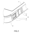
- FIG. 3 is a perspective view illustrating a waterproof case for an electronic device according to the embodiment of the present invention, which shows a state before a double locking unit is operated
- FIG. 4 is a sectional view illustrating a waterproof case for an electronic device according to the embodiment of the present invention, which shows a state before a double locking unit is operated
- FIG. 5 is a sectional view illustrating a waterproof case for an electronic device according to the embodiment of the present invention, which shows a state in which a double locking unit is operated.
- the double locking unit 50 includes a locking hole 51 formed in the body 20 of the waterproof case 10, a first locker 52 formed on the door 30, a locking groove 53 formed on the body 20, and a second locker 54.
- the first locker 52 is formed on the door 30 to be firstly fastened with or released from the locking hole 51 when the door 30 pivotally rotates around the hinge 31.
- the second locker 54 is movably disposed in the locking groove 53, and moves in the locking groove 53 to secondly support that the first locker 52 is locked in or released from the locking hole 51. As shown in FIGS.
- the second locker 54 has at least one stopper 70 which is engaged with at least one stopping protrusion 25 or 26 formed on the body 20 so as to restrict the movement of the second locker 54.
- the stopper 70 includes first and second stopping grooves 71 and 72, of which the first stopping groove 71 is engaged with the first stopping protrusion 25 formed on the body 20 of the waterproof case 10, and the second stopping groove 72 is engaged with the second stopping groove 26 of the body 20 of the waterproof case 10.
- the body 20 of the waterproof case 10 includes a front cover 21, a window 22, and a rear cover 23.
- the front cover 21 has an opening 21a formed therein, to which the window 22 made of a transparent material is attached.
- the window 22 is made of the transparent material and attached to a front surface of the front cover 21, through which a user can view a display unit (not shown) of the electronic device 1 inserted in the front cover 21.
- the rear cover 23 is combined with the front cover 21 to cover a rear portion of the front cover 21.
- front cover 21 and the rear cover 23 are adhered by an ultrasonic welding.
- the front cover 21 is made of a synthetic resin material and has a rubber material attached to an inside surface thereof. Accordingly, the rubber material inside of the front cover 21 can protect the electronic device 1 from an applied external impact.
- the door 30 includes a hinge 31 which has a side hinge arm (not shown) formed on the body 20, and a center hinge arm (not shown) formed on the door 30 and pivotally assembled with the side hinge arm. Further, the door 30 includes an earphone jack cover 32 and an interface cover 33, which respectively waterproof an earphone jack hole 30c and an interface hole 30d.
- the door 30 has a microphone hole 30a and a speaker hole 30b formed therein, and a waterproof member 34 to waterproof the microphone hole 30a and the speaker hole 30b.
- the waterproof member 34 is made of a waterproof material such as PTEE or TEMISH.
- the waterproof member 34 prevents water from permeating to a microphone (not shown) and a speaker (not shown) of the electronic device 1, even though the body 20 of the waterproof case 10 is put in water.
- the waterproof member 4 may be made of other synthetic resin materials as well as the synthetic resin material such as PTEE or TEMISH.
- the elastic member 40 includes an elastic band made of a rubber material, at both ends of which mounting portions 41 are combined with protrusions 24 formed in the body 20 of the waterproof case 10 so as to fix the elastic band to the body 20.
- the elastic band made of the rubber material is described as an example of the elastic member 40, but the elastic member is not limited to the elastic band. That is, any configuration capable of pushing the electronic device 1 out of the body 20 by its elasticity can be applied to the present invention, as another example of the elastic member.
- FIG. 9 is a perspective view illustrating a waterproof case for an electronic device according to the embodiment of the present invention, which shows another example of an elastic member.
- the elastic member 40 includes a plate spring, at one end of which at least one locking hole 51 is formed and combined with at least one protrusion 20a formed in the body 20 so as to lock the plate spring to the body 20 of the waterproof case.
- the plate spring fixed to the body 20 of the waterproof case 10 is pushed and compressed by one end of the electronic device 1 contacting with the plate spring when the electronic device 1 is inserted in the body 20 of the waterproof case.
- the door 30 is opened and the compressed plate spring elastically expands to apply elasticity to the electronic device 1 inserted in the body 20 of the waterproof case 10, resulting in automatically pushing out the electronic device 1.
- FIG. 10 is a perspective view illustrating a waterproof case for an electronic device according to the embodiment of the present invention, which shows still another example of an elastic member.
- the elastic member 40 includes a coil spring, one end 60a of which is fixed to a fixed portion 201 formed in the body 20 of the waterproof case 10 and the other end 60b of which is coupled to a movement portion 202 mounted on the body 20 of the waterproof case 10.
- the coil spring is compressed or expanded as the movement portion 202 moves, at the same time when the coil spring comes in contact with the electronic device 1.
- the coil springs are disposed at both sides of the body 20 of the waterproof case.
- the electronic device 1 comes in contact with the movement portion 202 coupled to the other end 60b of the coil spring.
- the electronic device 1 and the movement portion 202 move together so as to compress the coil spring.
- the double locking unit 50 is released, the door 30 is opened and the compressed coil spring expands and provides an elastic force.
- the movement portion 202 is moved by the elastic force, while moving the electronic device 1. At this time, the electronic device 1 is automatically separated from the body 20 by the elastic force of the coil spring.
- the body 20 of the waterproof case includes the front cover 21 and the rear cover 23. Further, the window 22 made of the transparent material is attached to the front cover 21 to cover the opening 21 a.
- the elastic band is assembled to the front cover 21 by combining the fixing portions 41 formed at both ends of the elastic band to the protrusions. Then, the rear cover 23 is attached to the front cover 21 by the ultrasonic welding.
- the door 30 is connected to the body 20 in such a manner that the center hinge arm of the door 30 is coupled to the side hinge arm of the covers to pivotally rotate around a hinge axis A1.
- the door 30 includes the earphone jack cover 32 and the interface cover 33, and has the microphone hole 30a and the speaker hole 30b formed therein, in which the waterproof members 34 are respectively inserted in order to waterproof the microphone hole 30a and the speaker hole 30B.
- the door 30 further includes a silicon member 30e for preventing water from permeating to the waterproof case.
- the body 20 of the waterproof case is open at a lower portion thereof. Accordingly, the electronic device 1 can be inserted and removed through n inserting hole formed at the lower portion of the body 20 in/from the waterproof case 10.
- the elastic member 40 When the electronic device 1 is inserted at a predetermined depth in the body 20, it comes in contact with the elastic member 40. Then, when the electronic device 1 is fully inserted in the body 20 of the waterproof case 10, the elastic member 40 is bent. As a result, enough elastic force is generated to push the electronic device 1 out of the body of the waterproof case.
- the door 30 pivotally rotates around the hinge axis A1 so that the first locker 52 formed at one end of the door 30 is inserted into the locking hole 51 formed in the body 20 so as to firstly lock the waterproof case 10.
- the second locker 54 is moved in the locking groove 53, the second locker 54 comes in contact with a rear surface of the first locker 52, and secondly supports the locking of the first locker 52.
- the first stopping groove 71 formed in the second locker 54 is separated from the first stopping protrusion 25 of the body 20, and the second stopping groove 72 is engaged with the second stopping protrusion 26.
- the first and second stopping grooves 71 and 72 move together.
- the second stopping groove 72 is engaged with the second stopping protrusion 26 and restricts the movement of the second locker 54.
- the second locker 54 At the same time as when the second locker 54 comes in contact with the rear surface of the first locker 52, it supports the locking of the first locker 52 while preventing the first locker 52 from being separated from the locking hole 51. Accordingly, the first locker 52 is locked twice, thereby improving the locking performance of the door 30.
- the second locker 54 is pushed and moved in the locking groove 53.
- the first and second stopping grooves 71 and 72 of the second locker 54 are moved along with the second locker 54.
- the second stopping groove 72 is separated from the second stopping protrusion 26, and the first stopping groove 71 is engaged with the first stopping protrusion 25 so as to restrict the movement of the second locker 54.
- the second locker 54 is separated from the first locker 52 and withdraws the support for the locking of the first locker 52. Then, when the first locker 52 is pushed, the first locker 52 is bent and is released from the locking hole 51.
- the electronic device 1 When the door 30 is released, the electronic device 1 is simultaneously moved by the elastic force of the elastic member 40 and pushes the door 30 while being separated from the body 20.
- the door 30 opens the insertion hole 20a of the body 20.
- the electronic device 1 rotates the door 20 around the hinge axis A1 during the separation, and opens the body 20 of the waterproof case.
- the door 30 is firstly locked by the first locker 52 so as to prevent the electronic device 1 from being separated from the body 20 of the waterproof case. Furthermore, the first locker 52 is secondly locked by the second locker 54. Accordingly, the first locker 52 can prevent the door 30 from opening due to an external impact or an unconscious movement of a user. Of course, since the door 30 is not opened by means of the first and second lockers 52 and 54 under any impact, the electronic device 1 can be prevented from being separated.
- the elastic member 40 is provided to the door 30 of the body 20 of the waterproof case.
- the elastic member 40 provides elastic force to push the electronic device out of the waterproof case when the door 30 is open. Accordingly, it is possible to separate the electronic device from the waterproof case easily.
- the double locking unit 50 is established to the body of the waterproof case to lock the door twice. Therefore, it is possible to prevent the waterproof case from opening due to external impact or a fall.
Landscapes
- Engineering & Computer Science (AREA)
- Theoretical Computer Science (AREA)
- Computer Networks & Wireless Communication (AREA)
- Signal Processing (AREA)
- Computer Hardware Design (AREA)
- Human Computer Interaction (AREA)
- Physics & Mathematics (AREA)
- General Engineering & Computer Science (AREA)
- General Physics & Mathematics (AREA)
- Mechanical Engineering (AREA)
- Casings For Electric Apparatus (AREA)
Applications Claiming Priority (1)
| Application Number | Priority Date | Filing Date | Title |
|---|---|---|---|
| US13/904,352 US20140353178A1 (en) | 2013-05-29 | 2013-05-29 | Waterproofing device for electronic device |
Publications (2)
| Publication Number | Publication Date |
|---|---|
| EP2807944A2 true EP2807944A2 (de) | 2014-12-03 |
| EP2807944A3 EP2807944A3 (de) | 2015-08-05 |
Family
ID=49000318
Family Applications (1)
| Application Number | Title | Priority Date | Filing Date |
|---|---|---|---|
| EP13180461.9A Withdrawn EP2807944A3 (de) | 2013-05-29 | 2013-08-14 | Wasserdichtes Gehäuse für elektronische Vorrichtung |
Country Status (4)
| Country | Link |
|---|---|
| US (1) | US20140353178A1 (de) |
| EP (1) | EP2807944A3 (de) |
| KR (1) | KR20140141401A (de) |
| TW (1) | TW201444746A (de) |
Families Citing this family (25)
| Publication number | Priority date | Publication date | Assignee | Title |
|---|---|---|---|---|
| US9161597B2 (en) * | 2013-09-12 | 2015-10-20 | Otter Products, Llc | Protective case with internal suspension system |
| JP1522939S (de) * | 2014-09-10 | 2015-05-11 | ||
| KR20170034076A (ko) * | 2015-09-18 | 2017-03-28 | 삼성전자주식회사 | 전자 장치 및 그 기능 제어 방법 |
| KR200483755Y1 (ko) * | 2016-07-22 | 2017-06-20 | 홍석준 | 휴대폰 보호 케이스 |
| US9864257B1 (en) | 2016-09-19 | 2018-01-09 | Gopro, Inc. | Camera frame with side door |
| USD860181S1 (en) | 2017-01-20 | 2019-09-17 | Steven Wang | Mobile device case |
| US10413028B2 (en) * | 2017-01-20 | 2019-09-17 | Steven Wang | Mobile device case for wet environments |
| USD890835S1 (en) | 2017-12-28 | 2020-07-21 | Gopro, Inc. | Camera |
| KR102472235B1 (ko) * | 2018-07-19 | 2022-11-30 | 삼성전자주식회사 | 스피커 구조를 포함하는 전자 장치 |
| WO2020033389A1 (en) | 2018-08-07 | 2020-02-13 | Gopro, Inc. | Camera and camera mount |
| USD905786S1 (en) | 2018-08-31 | 2020-12-22 | Gopro, Inc. | Camera mount |
| USD894256S1 (en) | 2018-08-31 | 2020-08-25 | Gopro, Inc. | Camera mount |
| US10694083B1 (en) * | 2019-01-04 | 2020-06-23 | Gopro, Inc. | Camera expansion frames and modules |
| USD920419S1 (en) | 2019-09-17 | 2021-05-25 | Gopro, Inc. | Camera |
| US11696004B2 (en) | 2019-09-13 | 2023-07-04 | Gopro, Inc. | Image capture device |
| CN111258379B (zh) * | 2020-01-17 | 2021-06-01 | Oppo广东移动通信有限公司 | 电子组件及保护壳 |
| USD946074S1 (en) | 2020-08-14 | 2022-03-15 | Gopro, Inc. | Camera |
| KR20220150053A (ko) | 2021-05-03 | 2022-11-10 | 삼성전자주식회사 | 지지 부재를 포함하는 전자 장치 |
| USD1107775S1 (en) | 2022-08-04 | 2025-12-30 | Gopro, Inc. | Camera |
| US12321084B2 (en) | 2022-08-12 | 2025-06-03 | Gopro, Inc. | Interconnect mechanism for image capture device |
| US12379650B2 (en) | 2023-02-15 | 2025-08-05 | Gopro, Inc. | Reinforced image capture devices including interconnect mechanisms with a threaded accessory interface |
| US12574622B2 (en) | 2024-03-15 | 2026-03-10 | Gopro, Inc. | Image capture apparatus including a multi-function interconnect mechanism |
| USD1100025S1 (en) | 2024-03-15 | 2025-10-28 | Gopro, Inc. | Camera mount |
| USD1096914S1 (en) | 2024-03-15 | 2025-10-07 | Gopro, Inc. | Camera mount |
| USD1118735S1 (en) | 2024-05-22 | 2026-03-17 | Gopro, Inc. | Camera |
Family Cites Families (4)
| Publication number | Priority date | Publication date | Assignee | Title |
|---|---|---|---|---|
| DE4305705A1 (de) * | 1993-02-25 | 1994-09-01 | Erich Mekyska Kg | Behälter zur Aufbewahrung blatt-, platten- oder kartenförmiger Gegenstände |
| JP4432202B2 (ja) * | 2000-04-21 | 2010-03-17 | ソニー株式会社 | カード型記録媒体の収納ケースと収納ケースホルダと電子機器 |
| DE102008013524A1 (de) * | 2007-03-08 | 2008-10-30 | Freie Universität Berlin | Hartschalenbehälter für ein Notebook oder dergleichen |
| US8550714B2 (en) * | 2009-10-19 | 2013-10-08 | Alexander Danch | Sealable enclosure |
-
2013
- 2013-05-29 US US13/904,352 patent/US20140353178A1/en not_active Abandoned
- 2013-06-25 KR KR1020130073025A patent/KR20140141401A/ko not_active Abandoned
- 2013-08-14 EP EP13180461.9A patent/EP2807944A3/de not_active Withdrawn
- 2013-08-27 TW TW102130661A patent/TW201444746A/zh unknown
Non-Patent Citations (1)
| Title |
|---|
| None |
Also Published As
| Publication number | Publication date |
|---|---|
| US20140353178A1 (en) | 2014-12-04 |
| TW201444746A (zh) | 2014-12-01 |
| KR20140141401A (ko) | 2014-12-10 |
| EP2807944A3 (de) | 2015-08-05 |
Similar Documents
| Publication | Publication Date | Title |
|---|---|---|
| EP2807944A2 (de) | Wasserdichtes Gehäuse für elektronische Vorrichtung | |
| US20140353179A1 (en) | Waterproof case for electronic device | |
| US11031969B2 (en) | Protective case for electronic device | |
| US9614569B2 (en) | Waterproof casing with exposed display surface | |
| US20120305422A1 (en) | Portable device protector case | |
| US8051980B2 (en) | Protective sleeve for portable electronic devices | |
| CN202487878U (zh) | 电子设备的外插卡插拔装置 | |
| TWI580333B (zh) | 用於可攜式電子裝置的保護殼體結構 | |
| US7762827B2 (en) | Card assembly with a hinged cover including a torsion spring | |
| US20170353208A1 (en) | Mobile device case with integrated locking assembly | |
| US7889493B2 (en) | Cover structure and electronic device using the same | |
| US8300388B2 (en) | Accessory strap securing mechanism | |
| US20060154520A1 (en) | Lid for mobile communication terminal and mobile communication terminal | |
| US8264836B2 (en) | Battery cover latching mechanism and electronic device using the same | |
| US10931057B2 (en) | Waterproof ejection mechanism for a card connector | |
| US20060231619A1 (en) | Electronic device capable of ejecting a card when a cover is opened | |
| EP2381653B1 (de) | Tragbare elektronische Vorrichtung mit Anschlussport | |
| CN103427224A (zh) | 移动终端 | |
| CN102324654B (zh) | 具有顶出机构的电子设备 | |
| KR200473245Y1 (ko) | 휴대 단말기용 케이스 | |
| KR102626226B1 (ko) | 폴더블 휴대기기용 부착형 자동 힌지 보호 커버 | |
| US8923001B2 (en) | Chip card protecting cover assembly and electronic device using same | |
| KR20110011234U (ko) | 휴대 단말기용 케이스 | |
| KR100845222B1 (ko) | 휴대폰의 플립형 덮개 | |
| KR200487167Y1 (ko) | 보호 커버 |
Legal Events
| Date | Code | Title | Description |
|---|---|---|---|
| PUAI | Public reference made under article 153(3) epc to a published international application that has entered the european phase |
Free format text: ORIGINAL CODE: 0009012 |
|
| 17P | Request for examination filed |
Effective date: 20130814 |
|
| AK | Designated contracting states |
Kind code of ref document: A2 Designated state(s): AL AT BE BG CH CY CZ DE DK EE ES FI FR GB GR HR HU IE IS IT LI LT LU LV MC MK MT NL NO PL PT RO RS SE SI SK SM TR |
|
| AX | Request for extension of the european patent |
Extension state: BA ME |
|
| PUAL | Search report despatched |
Free format text: ORIGINAL CODE: 0009013 |
|
| AK | Designated contracting states |
Kind code of ref document: A3 Designated state(s): AL AT BE BG CH CY CZ DE DK EE ES FI FR GB GR HR HU IE IS IT LI LT LU LV MC MK MT NL NO PL PT RO RS SE SI SK SM TR |
|
| AX | Request for extension of the european patent |
Extension state: BA ME |
|
| RIC1 | Information provided on ipc code assigned before grant |
Ipc: A45C 11/00 20060101AFI20150630BHEP Ipc: A45C 13/00 20060101ALI20150630BHEP |
|
| STAA | Information on the status of an ep patent application or granted ep patent |
Free format text: STATUS: THE APPLICATION IS DEEMED TO BE WITHDRAWN |
|
| 18D | Application deemed to be withdrawn |
Effective date: 20160206 |